Project - Speed Control of a Direct Current (DC) motor
Project :-In this project, a Simulink model for the DC motor will be first developed per the schematic shown in Figure 1.
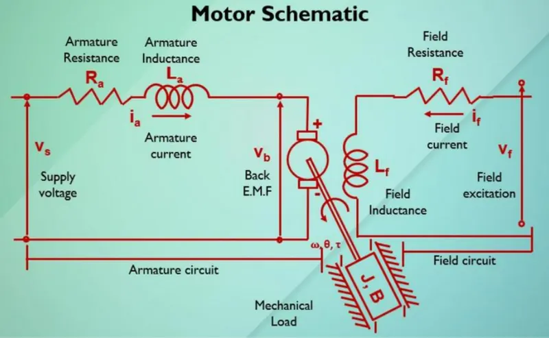
Ans)
>> For this above schematic Diagram ,we will assume the Input odf the dc moter is Voltage source(Vs) and out of the moter is Rotational speed (w) of the moter shaft.
>>Both the rotor and shaft are to rigid then we gets the Viscus friction(J) and Tarque(T).
>> The Tarque (T) of the motor is prapotional to the armature Current (ia) with tarque Constant (Kt)
i.e., T=Kt * ia-----------(1)
>> Back EMF (Vb) is praportional to angular velocity (theta_dot) by a praportional constatnt (Kb)
i,e., Vb = Kb * (theta_dot)----------(2)
>>For creating the The SIMULINK MODEL of above given DC moter let us find the transfer funcion as followes ::-
From the schematic diagram we have apply kirchoff's Voltage law To the Armature Circuit as Given below:-
Armature Circuit Equatation Part :-
Vs= Ra* ia + L (dia/ dt) +Vb ----------(3)
substitute eqn (2) in eqn (3) then we get
Vs= Ra* ia + L (dia/ dt) +(Kb* (theta_dot)-----------(4)
Vs-(Kb* (theta_dot)=Ra* ia + L (dia/ dt)------------(5)
From Equatation (5) we can write as :-
L( d ia / dt ) = (Vs-(Kb* (theta_dot)-Ra*ia)-----------(6)
Field Circuit Equatation Part:-
Appling the Newton's Law of Moton for Field circuit Then we get:-
J(d^2 theta /d t^2) + B (d theta /d t)= Kt * ia---------------(7)
Aplly Laplace Transforms to both equatations (6) and (7) then :-
from eqn (6) :-
L I(S)=V(S)- Kb (theta (S)- Ra I(S)
L I(S)+ Ra I(S)=V(S)- Kb (theta (S)
I(S) (L+Ra)=V(S)- Kb (theta (S)
I(S)=V(S)- Kb (theta (S) / (L+Ra)-----------------(8)
From eqn (7):-
J S^2 (theta (S))+ B s (theta (S)) =kt * I(S)---------------(9)
substitute I(S) value in eqn (9) then we get :-
J S^2 (theta (S))+ B s (theta (S)) =kt *{V(S)- Kb (theta (S) / (L+Ra)}
S * theta (S) ( J S +B)=kt *{V(S)- Kb (theta (S) / (L S+Ra)}---------------------(10)
From equatation (10) We get transfer function between output (w(s)) Angular velocity and input volatge (Vs) as followes :-
W(S) / Vs = Kt / {(L S+Ra) (J S + B)+Kt* Kb}-----------------(11)
Mathematical modeling from the first principles:-
From eqn (11) this we can design the SIMULINK MODEL:-
W(S) / Vs = Kt / {(L S+Ra) (J S + B)+Kt* Kb}
gain :-To return the output signal as gain of input signal
sum:- to return the output signal as sum of input signal
in1:- To generate the input signal port
out1:- to generate thw output signal port
Transfer funcrion :-To return the out as transfer function format of input given signals.
MATHEMATICAL_SIMULINK_MODEL:-
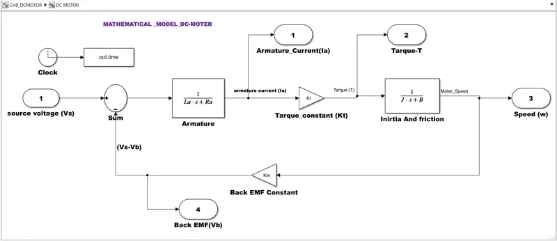
(Fig-1)
Design_parameters for Subsystem:-
PROCEDURE :-
For Creating This model ,
i)firstly we created the Two transfor functions one is ''armature part'' and seconf one is related to moment of inertia and friction constant
ii)Now we are subtracting the Source voltage from back EMF (Vb) by using the sum block.
and this is added to the input signal as Armature Transfer function
iii0After We are creating the tarque BY using gain and armature transfer Function we can obser this in above Model.
iv) After this can uses to produe the Speed of DC moter By usinhg inertia and friction constant as shown in above block.
v)We can give the In1 and OUt1 as to know the input signals and Output signals respectively.
From Above steps we can get the Mathematical Model Of DC moter (Fig-1).
THis Entire All blocks cen be converted as SINGLE-SUBSYSTEM By using following steps :-
Step-1) Select all the Blocks of above model.
step2) After select the blocks Right Click on the selected model.Then u get the dialg box
Step3) From that dialogbox we can select the ''Create Subsystem from selection'' icon then we gat all The blocks in signal subsystem model and named as DC motor. (Fig-2)
This can be shown in below:-
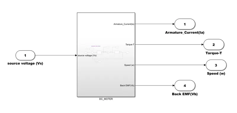
(Fig-2)
Use the Proportional, Integral, and Derivative (PID) control design knowledge gained in the training to design, develop and test a controller to maintain a desired speed for the motor.
CONTROL LAW DESIGNA AND TEST:-
This can be obtained from below controller design of dc motor:-
PID CONTROLLERE:-
NOW we can create the PID controller for controlling the abobe created DC Moter as followes:-
SIMULINK_BLOCKS:-
Clock:-To return the time as output signal
To work space:-To save the output in workspace
Step:-To generate the Pulse signal as output with adding two step signals.
gain :-To return the output signal as gain of input signal
sum:- to return the output signal as sum of input signal
Integrator:- To return the output signal in form of Integration of input signal
scope:- To Represent the Output in Graphical formation.
PID CONTROLLER SIMULINK MODEL:-
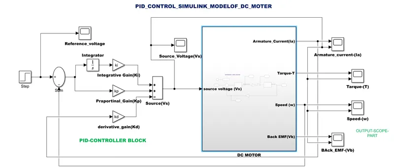
(Fig-3)
PROCEDURE :-
PID_CONTROL_BLOCK:-
i)Here we are giving the voltage as the reference signal by using the Step function to the Dc motor.
i)For getting error signal(e(t)) We can subtract the actuval speed to reference voltege by using sum block.
ii) After That this reference error signal can be addaed to the two gains values (Kp-Ki) by using sum block.
iii)And iThe ntigration gain(Ki) is tuned manually.
iv) after finally we can subtract the derivative gain(Kd) followed by the actually speed of motor feedback through by using sum block.
v) This total output value is given to the Input source signal to the Subsystem blosk we can obser this in (fig-3) above attached Simulink model.
OUTPUT_SCOPE_PART:-
>>> This Part is used to represent the Output signals in graphical represenatation by using scope blocks.
For creating this model we required the following parameters:-
%%% Assumed_parameters_parameters_values
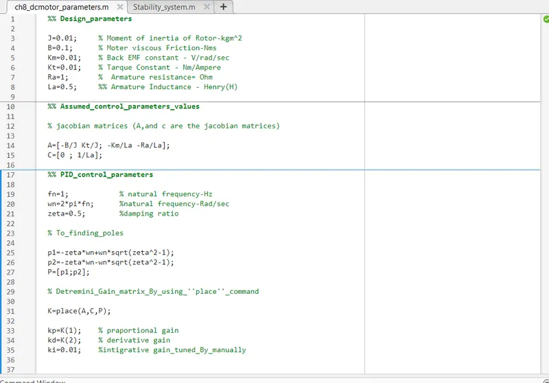
>> ch8_dcmotor_parameters
>> A
A =
-10.0000 1.0000
-0.0200 -2.0000
>> C
C =
0
2
>> K
K =
38.3133 -2.8584
>> kp
kp =
38.3133
>> kd
kd =
-2.8584
>> ki
ki =
0.0100
>>
SCOPES_AS FOLLOWES:-
1)SCOPE_OF_REFERENCE:-
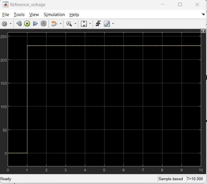
>> From above graph we can observe that the reference value is start the step at 1sec and upto 230 then its gets her equlibrium position.
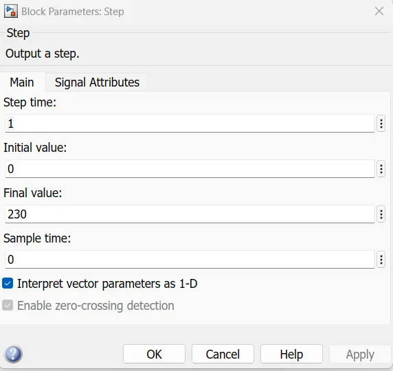
Reference_parameres_block:-
SOURCE_VOLTAGE_SCOPE:-
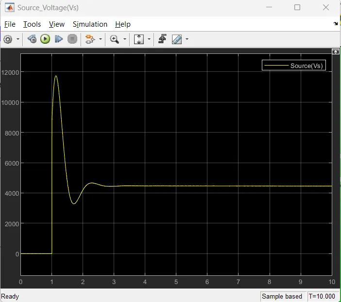
>> from above graph we can observe that the raises the peak value upto 11500 at 1.0 sec-1.15sec
>> after it fallen downs to 3500 at nearly 1.5 sec and
>>then after its gets gets its steady state position from (3.1 sec )
SCOPE-OF-ARMATURE CURRENT(ia):-
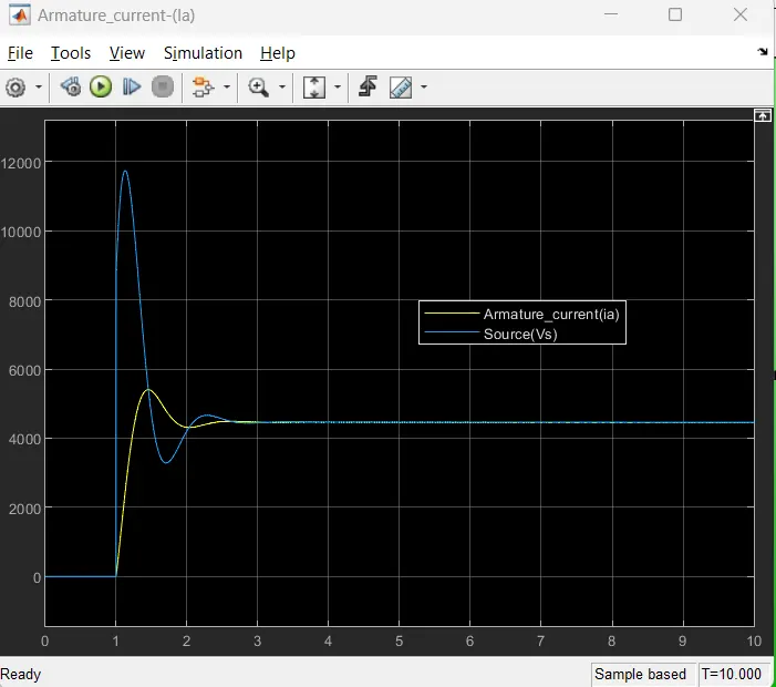
>>From above we can see the Blue line is Source volatge
>> yellow line is DC moter armature current (ia)
>>we can see that the armature currentraises to the 11900 nearly at 1.2 sec -1.45 sec and gets its overshoot value
>> nearly at 1.45 sec -1.95 sec gets undershoot value and
>> after that nearly 2.5sec this gets steady state position
SCOPE-OF-ARMATURE TARQUE:-
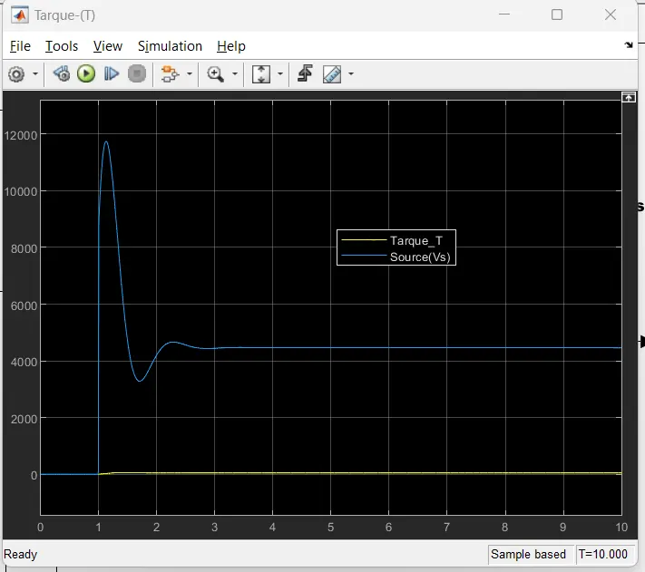
>>From above we can see the Blue line is Source volatge
>> yellow line is DC moter Tarque (T)
>>>>The tarque of the motor gets its steady state position nearl 2.0sec.
>> this can observe that in above graph scope.
SCOPE-OF-SPEED(W):-
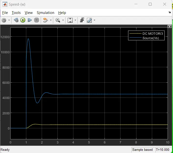
>>From above we can see the Blue line is Source volatge
>> yellow line is DC moter speed (w)
>> we can see the Speed(w) gets some tiny ivershoot at 1.5 sec to 1.85sec.And finally gets its steady state position at nearly 2.5sec.
>>The can observe that in above garph scope.
SCOPE-OF-BACK EMF:-
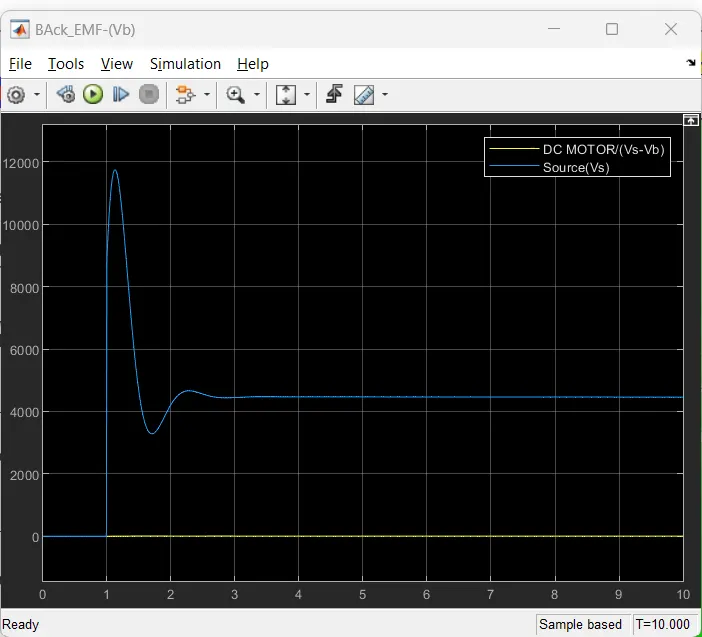
>>From above we can see the Blue line is Source volatge
>> yellow line is DC moter BACK EMF.(Vb)
>>we can obsreve from the above graph the back EMf is remains stady state position comapred to source voltage.
-----------------------------------------------------------------------------------------------------------------------------------------------------------------------------------------------------------------------------------------------------------------------------------------------------------------
STABILITY OF DYNAMIC SYSTEM:-
>>Stability of a dynamic system can be depends on the position of poles in maping system.
>>If the oles are laying the left half the s-plane then the dynamic system becomes stable.
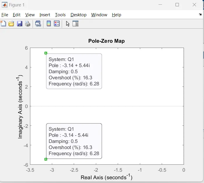
>>This dynamic system stability can be determined by using MATLAB command ''pzmap''.
>> For given Transfer function the poles are given as below
p1
p1 =
-3.1416 + 5.4414i
>> p2
p2 =
-3.1416 - 5.4414i
And this a both poles are lie on the left hand side of the S-plane, This indicates the system is stable .
>> this can be proved by using ''pzmap'' MATLAB command, can be aatached below.
>> This can be writen in MATLAB by follwing sytex:-
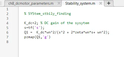
The output of Above script :-
Script (2)
>>From above graph the two poles (green_colour cross marks ) are shown with values in S-plane.
>> from the above ''pzmap'' we can observe that the both poles(p1 =-3.1416 + 5.4414 and p2 =-3.1416 - 5.4414i)are layied in left hand in the S-plane
>>That means this given Dynamic system is stable position.
---------------------------------------------------------------------------------------------------------------------------------
The Total Required deliverables are attaced in this above Created Project.
--------------------------------------------------------------------------------------------------------------------------------
(The End)