Project 2
PROJECT-2
Question:-
Design RMxprt model for the BLDC motor and induction motor by taking the same power rating and stator and rotor material for both the motors(for other design data use the Q11 and Q12 challenges)
- compare the results for both the motor
- prepare a detailed report on it
- by using the datasheet in ANSYS RMxprt, design MATLAB model of induction motor and compare the toque-speed curve for both Ansys and MATLAB model
Aim:-
The Main aim is Create the Design RMxprt model for the BLDC motor and induction motor by taking the same power rating and stator and rotor material for both the motors.
ANSWER:-
BLDC Motor:-
A brushless DC motor (known as BLDC) is a permanent magnet synchronous electric motor which is driven by direct current (DC) electricity and it accomplishes electronically controlled commutation system (commutation is the process of producing rotational torque in the motor by changing phase currents through it at appropriate times) instead of a mechanically commutation system. BLDC motors are also referred as trapezoidal permanent magnet motors.
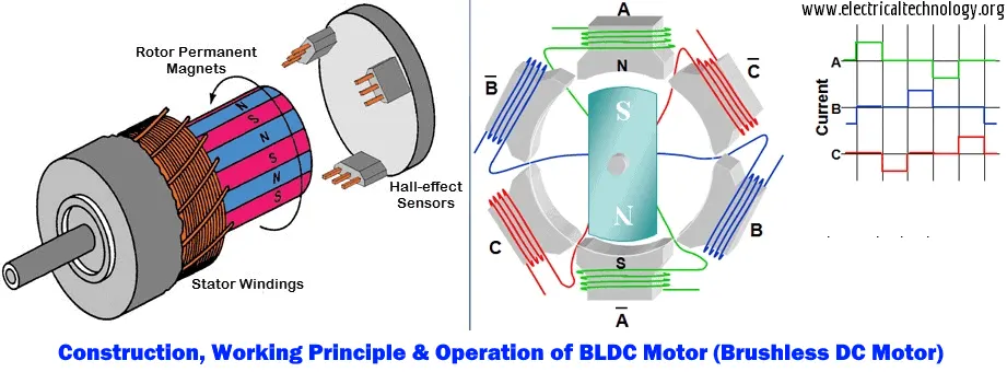
Modeling using RMxpert:-
RMxpert:-
RMxprt stands for Rotating Machine Expert is a template-based design tool of the ANSYS – Maxwell suite used to create a customized machine design flow to meet the demand for higher efficiency. Using classical analytical motor theory and equivalent magnetic circuit methods.
RMxprt can calculate machine performance, make initial sizing decisions and perform numerous "what if" analyses. RMxprt is able to automatically set up a complete Maxwell project (2-D/3-D) including geometry, materials, and boundary conditions. The setup includes the appropriate symmetries and excitations with coupling circuit topology for electromagnetic transient analysis.
For creating the model of "BLDC" Using RMxpert by following steps:-
Open the ANSYS softwere and click on the "MAXwell" Top Ribben and choose the RMXpert as follows
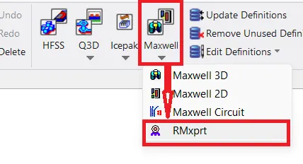
Then a Nwe Windoe is apper as follows
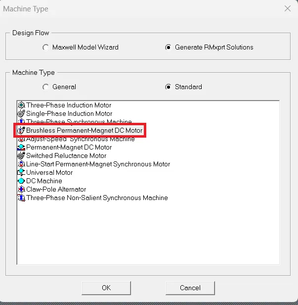
>>From this Window choose the MAchine Type as for the requirement brushless dc perminent motor.
Now after selecting the machine type then we get the project manager windoe as follows.
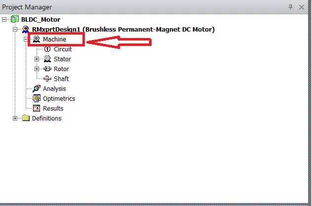
Now we have to enter the values machine details as for thegiven data
Given data:-
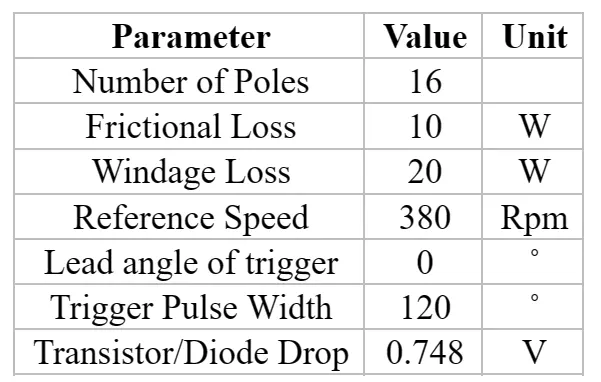
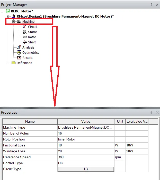
Enter the values in RMXpert model as follows.
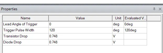
Now we have to select the values for the Stator and and slot valuesas for the given data:-
Given data:-
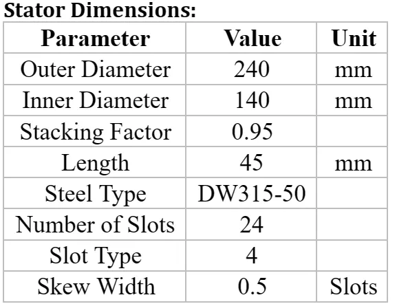
Enter the values in RMXpert model as follows.:-
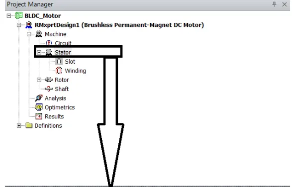
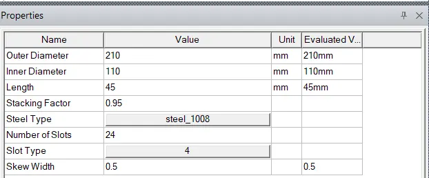
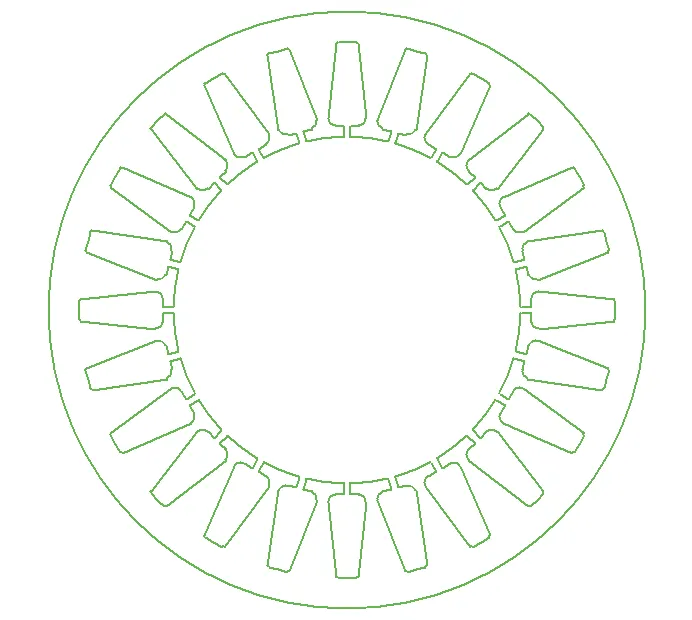
Then The stator part is looks as follows.
Now we have to enter the values for the slot as for the given data:-
Given data:-
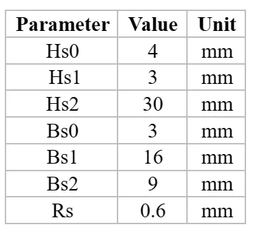
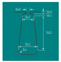
Enter the values in RMXpert model as follows.:-
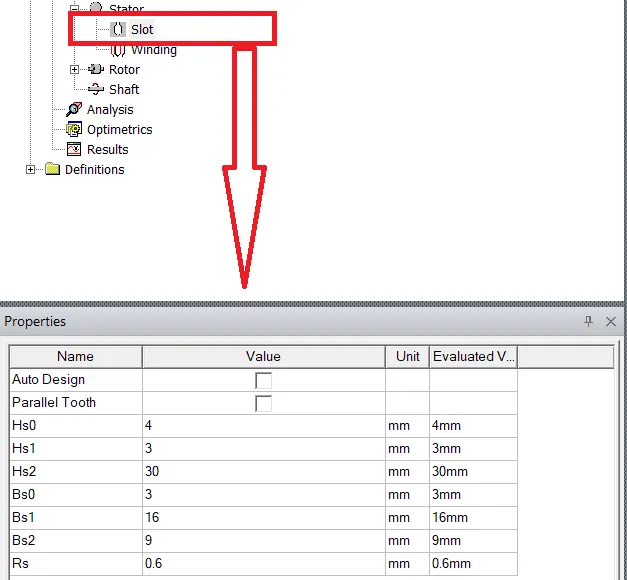
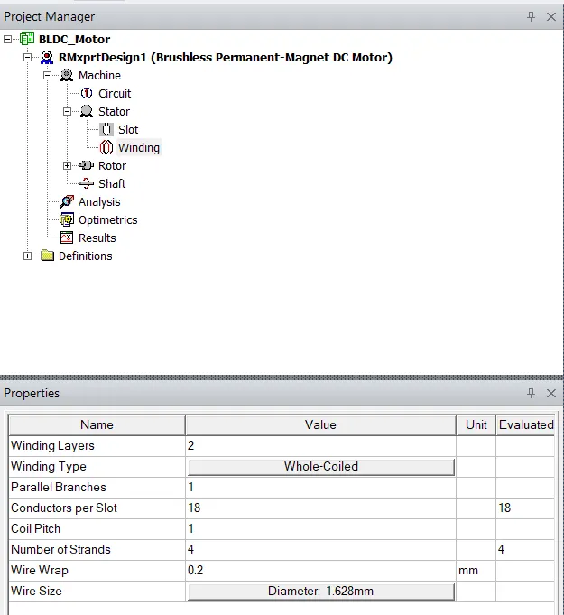
Now we have to enter the values for the winding as for the given data:-
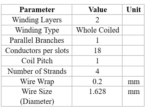
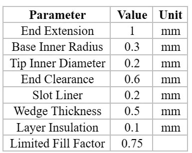
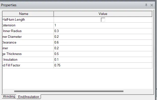
winding parameters End/Insulation Data
Enter the values in RMXpert model as follows.:-
End/Insulation Data:-
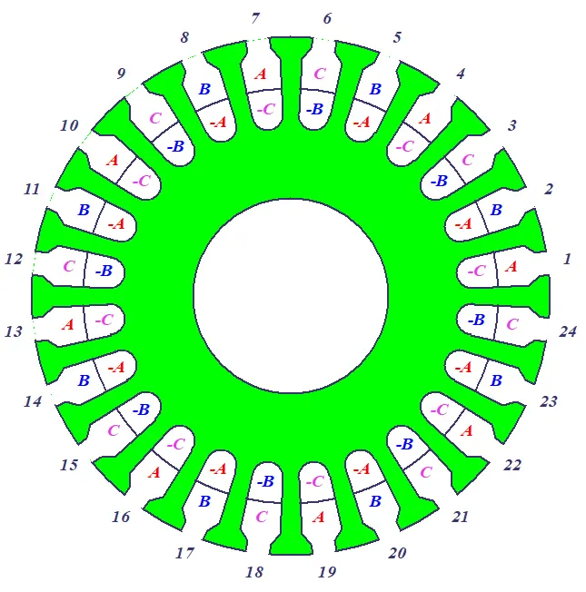
The winding image in RMXpert will looks as follows.
Now we have to enter the values for the Rotor as per the given data
Given data:-
Rotor Dimensitions :
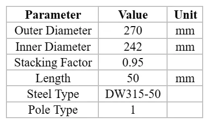
Enter the values in RMXpert model as follows.:-

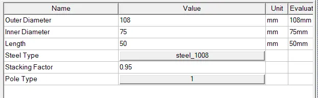
Now we have to enter the values for the pole data as folloes;
Given data:-
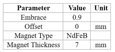
Enter the values in RMXpert model as follows.:-
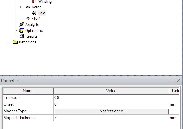
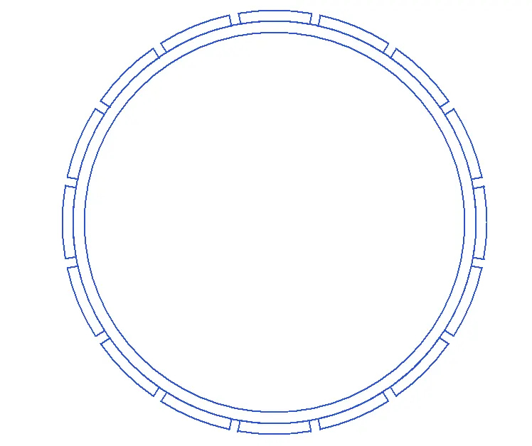
Then the rotor is as follows :-
Now we have to add the step for the analyse as follows.
Given data :-
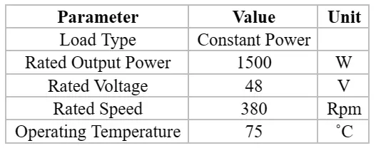
Analysis Setup data
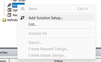
>>Rigt click on analysis icon and click om=n the add solution setup then we get the window as follows.
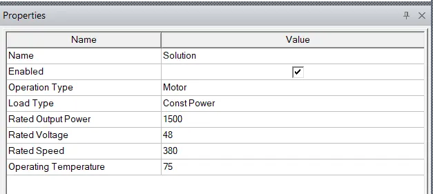
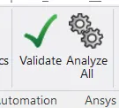
after completion of required modeling and analyse parameters now we have to analyse the designed motor as follows.
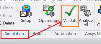
After click on the Validate we have to get the windoew as follows.
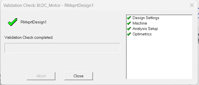
now click on the analyse all
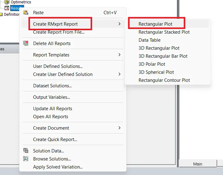
Noiw right click on the results as foolows
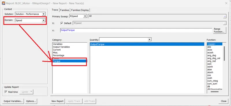
Then we get the windoe as follows.
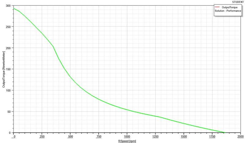
The Torque-speed curve For BLDC motor As follows:-
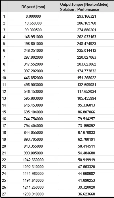
The Table for the SPEED vs TORQUE curve:-
RESULT:-
The RMxprt model for the BLDC motor is Designed and analysed successfully.
---------------------------------------------------------------------------------------------------------------------------------------------
***3-Phase Induction Motor***
A three phase induction motor is a type of AC induction motors which operates on three phase supply as compared to the single phase induction motor where single phase supply is needed to operate it.
The three phase supply current produces an electromagnetic field in the stator winding which leads to generate the torque in the rotor winding of three phase induction motor having magnetic field.
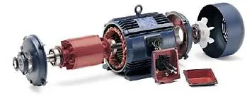
Three phase Induction motor
Modeling using RMxpert:-
RMxpert:-
RMxprt stands for Rotating Machine Expert is a template-based design tool of the ANSYS – Maxwell suite used to create a customized machine design flow to meet the demand for higher efficiency. Using classical analytical motor theory and equivalent magnetic circuit methods.
RMxprt can calculate machine performance, make initial sizing decisions and perform numerous "what if" analyses. RMxprt is able to automatically set up a complete Maxwell project (2-D/3-D) including geometry, materials, and boundary conditions. The setup includes the appropriate symmetries and excitations with coupling circuit topology for electromagnetic transient analysis.
For creating the model of "BLDC" Using RMxpert by following steps:-
Open the ANSYS softwere and click on the "MAXwell" Top Ribben and choose the RMXpert as follows
Then a Nwe Windoe is apper as follows
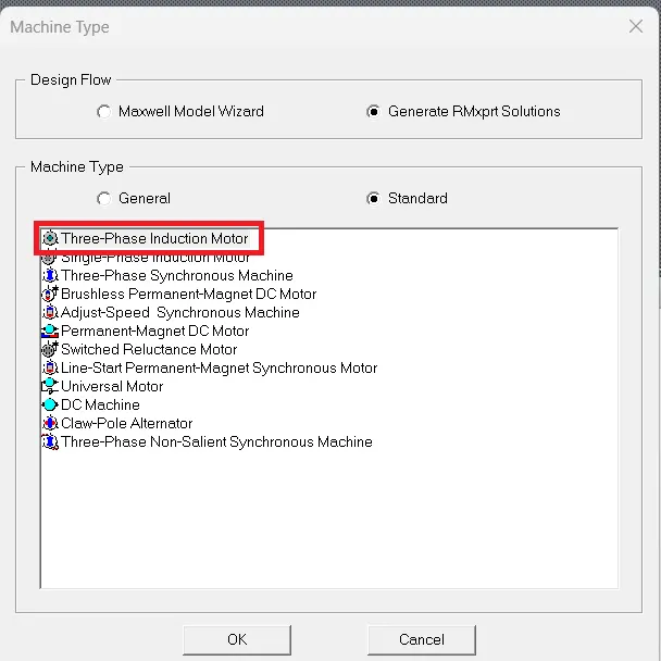
>>From this Window choose the MAchine Type as for the requirement brushless dc perminent motor.
Now after selecting the machine type then we get the project manager windoe as follows.
Now we have to enter the values machine details as for thegiven data
Given data:-
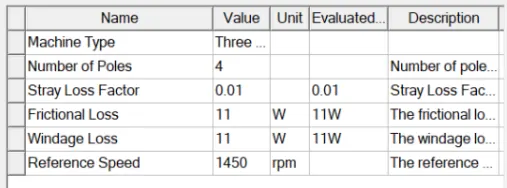
Enter the values in RMXpert model as follows:-
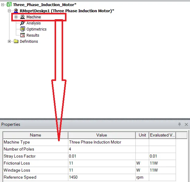
Now we have to select the values for the Stator and and slot valuesas for the given data:-
Given data:-
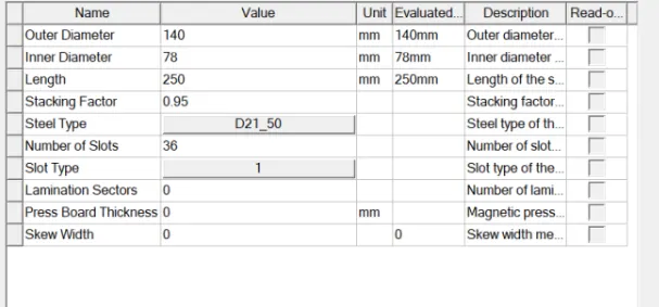
Enter the values in RMXpert model as follows:-
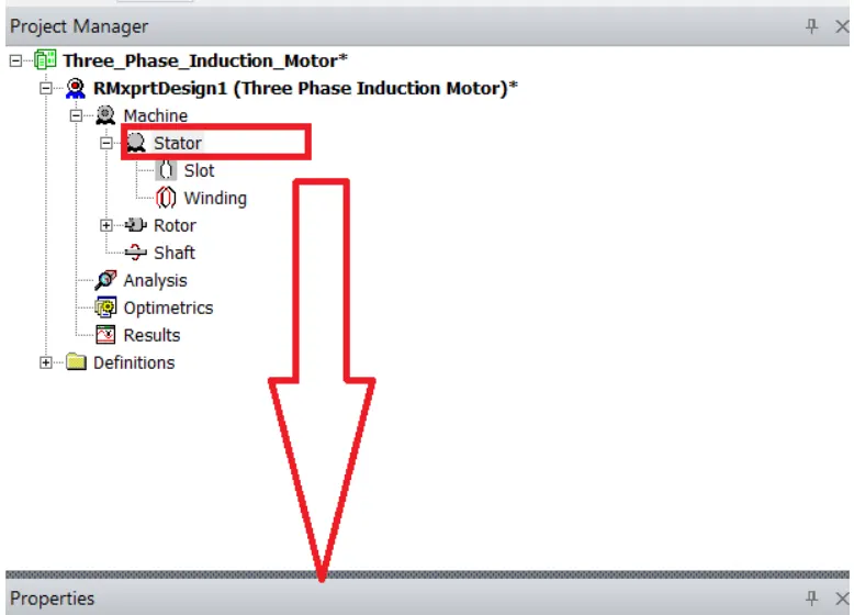
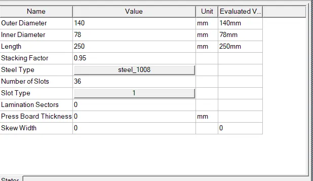
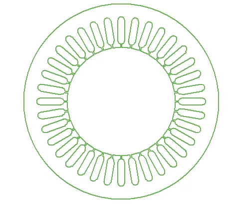
Then The stator part is looks as follows:-
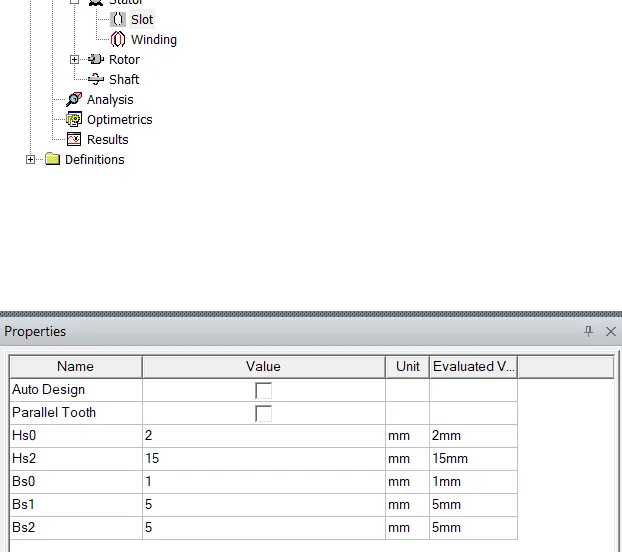
Now we have to enter the values for the slot as for the given data:-
Given data:-
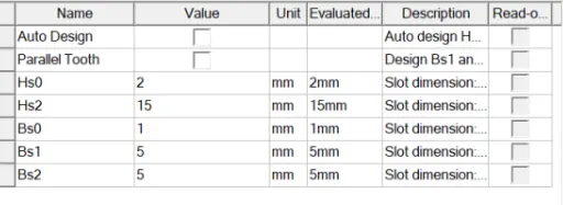
Enter the values in RMXpert model as follows:-
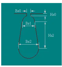
Now we have to enter the values for the winding as for the given data:-
Given data:-
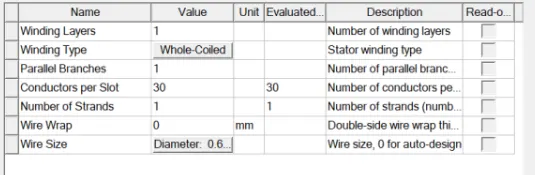
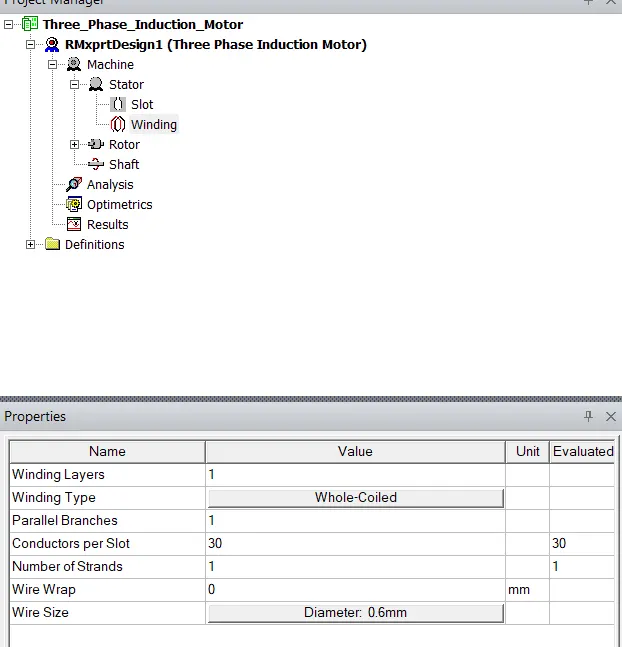
Enter the values in RMXpert model as follows:-
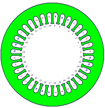
The winding image in RMXpert will looks as follows:-
Now we have to enter the values for the Rotor as per the given data
Given data:-
Rotor Dimensitions :-
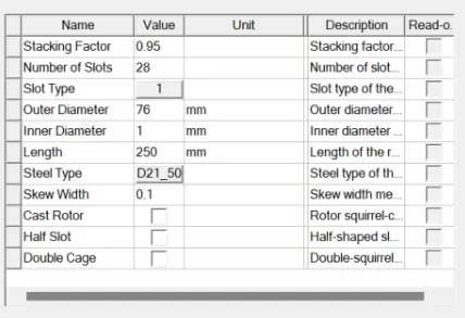
Enter the values in RMXpert model as follows:-
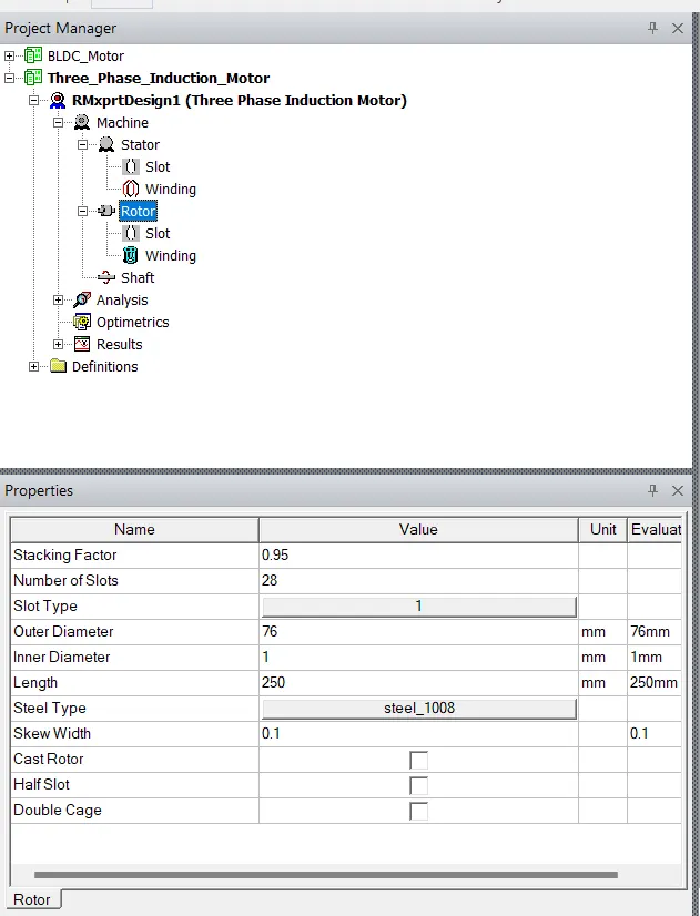
Now we have to enter the values for the slot as for the given data:-
Given data:-
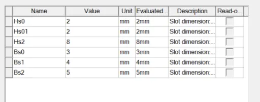
Enter the values in RMXpert model as follows:-
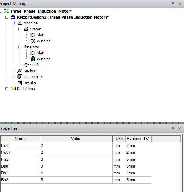
Now we have to enter the values for the winding as for the given data:-
Given data:-
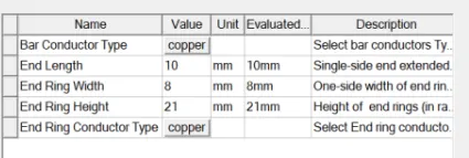
Enter the values in RMXpert model as follows:-
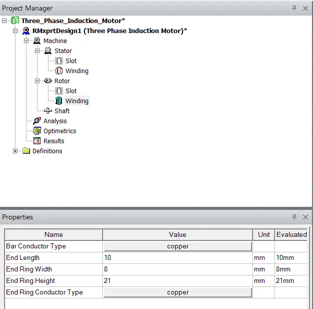
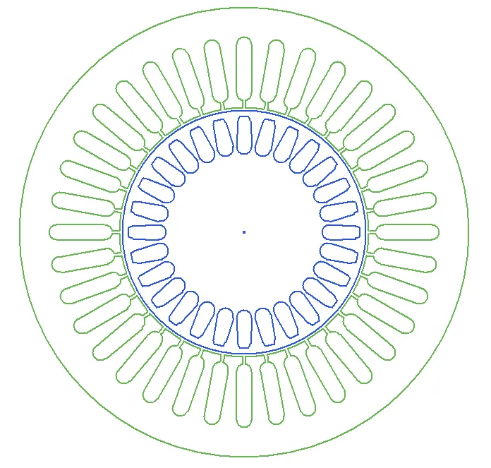
Then the winding and Rotor will lookas as follows :-
Now we have to add the step for the analyse as follows.
Given data :-
Analysis Setup data
>>Rigt click on analysis icon and click om=n the add solution setup then we get the window as follows.
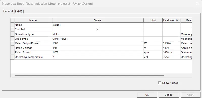
>>Then Click on okay.
after completion of required modeling and analyse parameters now we have to analyse the designed motor as follows.
After click on the Validate we have to get the windoew as follows.
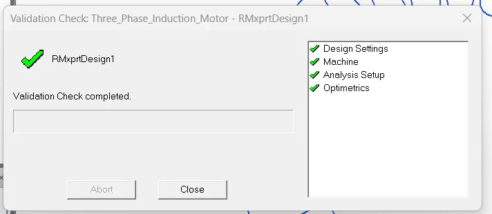
now click on the analyse all
Noiw right click on the results as foolows
Then we get the window as follows:-
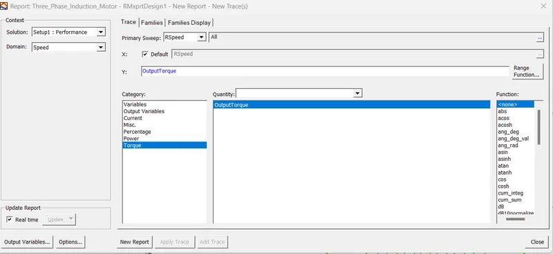
The Torque-speed curve For BLDC motor As follows:-
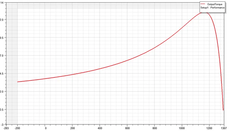
Fig(1):- RMxpert Model
The Table for the SPEED vs TORQUE curve:-
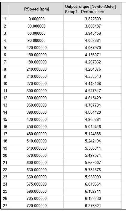
RESULT:-
The RMxprt model for the INDUCTION MOTOR is Designed and analysed successfully.
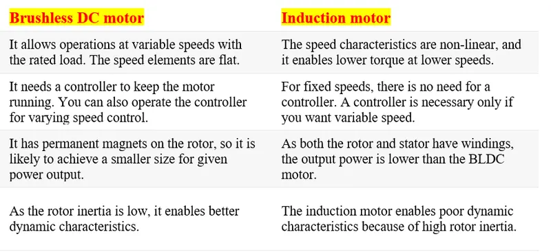
Comparision between BLDC and Induction Motor:-
Conclusion:-
The RMxprt model for the BLDC motor and induction motor by taking the same power rating and stator and rotor material for both the motors are created and exicuted Successfully.
By comparing the both Speed Torques charecteristics of the motors we can conclude that the BLDC having the Dynamic characteristics comparid to the Induiction motor.
--------------------------------------------------------------------------------------------------------------------------------------------
By using the datasheet in ANSYS RMxprt, design MATLAB model of induction motor and compare the toque-speed curve for both Ansys and MATLAB model.
Aim:-
The main aim is create the MATLAB model for the Induction motor and use the required parameters from the datasheet of RMxpert model.
ANSWER:-
The Datasheet From the ANSYS RMxprt is as follows:-
Three-Phase Induction Machine Design Sheet

                      File: Setup1.res

     GENERAL DATA

Given Output Power (kW):	1.5
Rated Voltage (V):	440
Winding Connection:	Wye
Number of Poles:	4
Given Speed (rpm):	1478
Frequency (Hz):	50
Stray Loss (W):	15
Frictional Loss (W):	11.2124
Windage Loss (W):	11.6496
Operation Mode:	Motor
Type of Load:	Constant Power
Operating Temperature (C):	75

     STATOR DATA

Number of Stator Slots:	36
Outer Diameter of Stator (mm):  	140
Inner Diameter of Stator (mm):  	78
Type of Stator Slot:	1
Stator Slot
            hs0 (mm):  	2
            hs2 (mm):  	15
            bs0 (mm):  	1
            bs1 (mm):  	5
            bs2 (mm):  	5
Top Tooth Width (mm):  	2.59221
Bottom Tooth Width (mm):  	5.20689

Length of Stator Core (mm):  	250
Stacking Factor of Stator Core:	0.95
Type of Steel:	steel_1008
Number of lamination sectors	0
Press board thickness (mm):  	0
Magnetic press board	No
Number of Parallel Branches:	1
Number of Layers:	1
Winding Type:	Whole Coiled
Coil Pitch:	0
Number of Conductors per Slot:	30
Number of Wires per Conductor:	1
Wire Diameter (mm):	0.6
Wire Wrap Thickness (mm):	0

Wedge Thickness (mm):	0
Slot Liner Thickness (mm):	0
Layer Insulation (mm):	0
Slot Area (mm^2):	96.6012
Net Slot Area (mm^2):	88.2805

Slot Fill Factor (%):	12.2337
Limited Slot Fill Factor (%):	75
Wire Resistivity (ohm.mm^2/m):	0.0217
Conductor Length Adjustment (mm):  	0
End Length Correction Factor	1
End Leakage Reactance Correction Factor	1

     ROTOR DATA

Number of Rotor Slots:	28
Air Gap (mm):  	1
Inner Diameter of Rotor (mm):  	1
Type of Rotor Slot:	1
Rotor Slot
            hs0 (mm):  	2
            hs01 (mm):  	2
            hs2 (mm):  	8
            bs0 (mm):  	3
            bs1 (mm):  	4
            bs2 (mm):  	5
Cast Rotor:	No
Half Slot:	No

Length of Rotor (mm):  	250
Stacking Factor of Rotor Core:	0.95
Type of Steel:	steel_1008
Skew Width:	0.1
End Length of Bar (mm):  	10
Height of End Ring (mm):  	21
Width of End Ring (mm):  	8
Resistivity of Rotor Bar
  at 75 Centigrade (ohm.mm^2/m):	0.020797
Resistivity of Rotor Ring
  at 75 Centigrade (ohm.mm^2/m):	0.020797
Magnetic Shaft:	Yes

     MATERIAL CONSUMPTION

Armature Copper Density (kg/m^3):  	8900
Rotor Bar Material Density (kg/m^3):  	8933
Rotor Ring Material Density (kg/m^3):  	8933
Armature Core Steel Density (kg/m^3):  	7872
Rotor Core Steel Density (kg/m^3):  	7872

Armature Copper Weight (kg):  	0.88026
Rotor Bar Material Weight (kg):  	3.51854
Rotor Ring Material Weight (kg):  	0.480902
Armature Core Steel Weight (kg):  	13.3448
Rotor Core Steel Weight (kg):  	5.75249
Total Net Weight (kg):  	23.977

Armature Core Steel Consumption (kg):  	29.2978
Rotor Core Steel Consumption (kg):  	8.93363

     RATED-LOAD OPERATION

Stator Resistance R1 (ohm):	8.949
Stator Resistance at 20C (ohm):	7.36128
Stator Leakage Reactance X1 (ohm):	4.95366
  Slot Leakage Reactance Xs1 (ohm):	3.94557
  End Leakage Reactance Xe1 (ohm):	0.688623
  Harmonic Leakage Reactance Xd1 (ohm):	0.319467
Rotor Resistance R2 (ohm):	1.51398
Rotor Leakage Reactance X2 (ohm):	29.3567
Resistance Corresponding to
  Iron-Core Loss Rfe (ohm):	7.0363e+07
Magnetizing Reactance Xm (ohm):	32.4358

Stator Phase Current (A):	7.95263
Current Corresponding to
  Iron-Core Loss (A):	2.65097e-06
Magnetizing Current (A):	5.75075
Rotor Phase Current (A):	3.27677

Copper Loss of Stator Winding (W):	1697.92
Copper Loss of Rotor Winding (W):	48.7679
Iron-Core Loss (W):	0.00148346
Frictional and Windage Loss (W):	22.1045
Stray Loss (W):	15.0013
Total Loss (W):	1783.8
Input Power (kW):	3.28393
Output Power (kW):	1.50013

Mechanical Shaft Torque (N.m):	9.8561
Efficiency (%):	45.6811
Power Factor:	0.539363
Rated Slip:	0.0310425
Rated Shaft Speed (rpm):	1453.44

     NO-LOAD OPERATION

No-Load Stator Resistance (ohm):	8.949
No-Load Stator Leakage Reactance (ohm):	4.95754
No-Load Rotor Resistance (ohm):	1.51385
No-Load Rotor Leakage Reactance (ohm):	139.952

No-Load Stator Phase Current (A):	6.60049
No-Load Iron-Core Loss (W):	0.00195364
No-Load Input Power (W):	1193.71
No-Load Power Factor:	0.237305
No-Load Slip:	0.000265256
No-Load Shaft Speed (rpm):	1499.6

     BREAK-DOWN OPERATION

Break-Down Slip:	0.09
Break-Down Torque (N.m):	13.5145
Break-Down Torque Ratio:	1.37118
Break-Down Phase Current (A):	10.5867

     LOCKED-ROTOR OPERATION

Locked-Rotor Torque (N.m):	3.82812
Locked-Rotor Phase Current (A):	15.1461
Locked-Rotor Torque Ratio:	0.388401
Locked-Rotor Current Ratio:	1.90454

Locked-Rotor Stator Resistance (ohm):	8.949
Locked-Rotor Stator
  Leakage Reactance (ohm):	4.93328
Locked-Rotor Rotor Resistance (ohm):	1.65319
Locked-Rotor Rotor
  Leakage Reactance (ohm):	11.7333

     DETAILED DATA AT RATED OPERATION

Stator Slot Leakage Reactance (ohm):	3.94557
Stator End-Winding Leakage
  Reactance (ohm):	0.688623
Stator Differential Leakage
  Reactance (ohm):	0.319467
Rotor Slot Leakage Reactance (ohm):	28.235
Rotor End-Winding Leakage
  Reactance (ohm):	0.509696
Rotor Differential Leakage
  Reactance (ohm):	0.596012
Skewing Leakage Reactance (ohm):	0.00271748

Stator Winding Factor:	0.959795

Stator-Teeth Flux Density (Tesla):	0.8698
Rotor-Teeth Flux Density (Tesla):	2.00518
Stator-Yoke Flux Density (Tesla):	1.07523
Rotor-Yoke Flux Density (Tesla):	0.42492
Air-Gap Flux Density (Tesla):	0.455085

Stator-Teeth Ampere Turns (A.T):	5.86519
Rotor-Teeth Ampere Turns (A.T):	222.949
Stator-Yoke Ampere Turns (A.T):	15.7751
Rotor-Yoke Ampere Turns (A.T):	1.4177
Air-Gap Ampere Turns (A.T):	374.759

Correction Factor for Magnetic
  Circuit Length of Stator Yoke:	0.679223
Correction Factor for Magnetic
  Circuit Length of Rotor Yoke:	0.7
Saturation Factor for Teeth:	1.61056
Saturation Factor for Teeth & Yoke:	1.65644
Induced-Voltage Factor:	0.734264

Stator Current Density (A/mm^2):	28.1267
Specific Electric Loading (A/mm):	35.0502
Stator Thermal Load (A^2/mm^3):	985.844

Rotor Bar Current Density (A/mm^2):	2.40199
Rotor Ring Current Density (A/mm^2):	1.62266

Half-Turn Length of
  Stator Winding (mm):  	323.895

     WINDING ARRANGEMENT

The 3-phase, 1-layer winding can be arranged in 18 slots as below:

AAAZZZBBBXXXCCCYYY

Average coil pitch is:	7.66667

Angle per slot (elec. degrees):	20
Phase-A axis (elec. degrees):	110
First slot center (elec. degrees):	0


     TRANSIENT FEA INPUT DATA

For one phase of the Stator Winding:
  Number of Turns:	180
  Parallel Branches:	1
  Terminal Resistance (ohm):	8.949
  End Leakage Inductance (H):	0.00219196
For Rotor End Ring Between Two Bars of One Side:
  Equivalent Ring Resistance (ohm):	1.52389e-06
  Equivalent Ring Inductance (H):	1.26255e-08
2D Equivalent Value:
  Equivalent Model Depth (mm):	250
  Equivalent Stator Stacking Factor:	0.95
  Equivalent Rotor Stacking Factor:	0.95
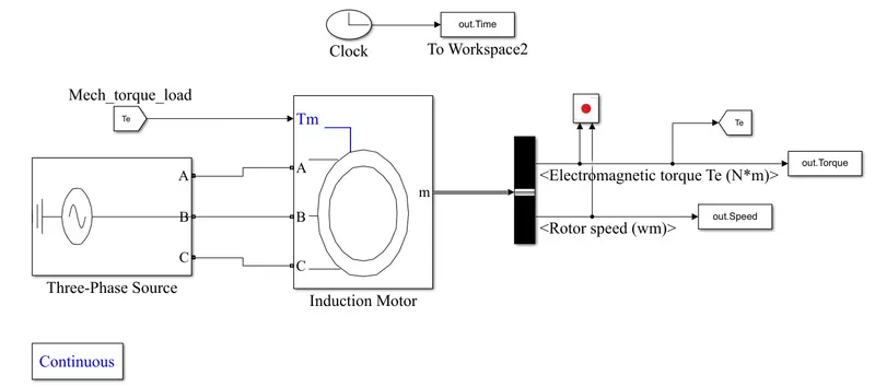
Simulink Model :-
Blocks used for the design the Simulink model is as follows:-
- Three phse supply
- Asynchronous Machine
- constant
- bus selector
- scope
Total Simulink model :-
Procedur:-
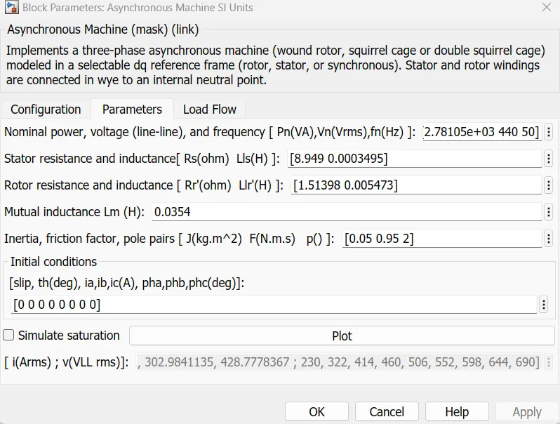
>>firstly we choose the Asynchronous Machine SI Units(InductionMotor) in simulink m=blocks.
>>After that the from the Datasheet we are adding the values for the motor parameters as follows.
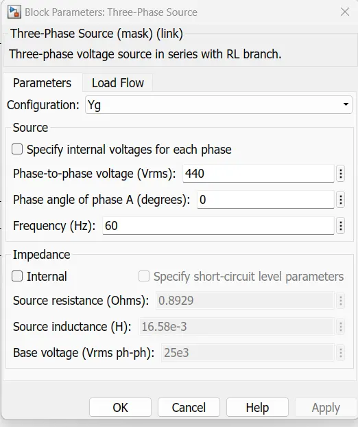
>>After assigning the values we took the "Three-Phase Source" bl;cok with following parametres .
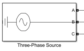
Parmeters values:-
>>>After that we assign the Tm values fom the Te for getting the bettwer values reference using the from and goto blocks.
>>We are using the Bus selector block for getting the output signals.
>>we are using the Xy-Graph for plotting the "Toque-speed curve "
Toque-speed curve as Follows:-
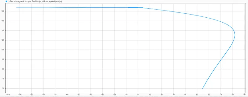
Fig(2):- Matlab Model
Compare the toque-speed curve for both Ansys and MATLAB model :-
By comparing the below images.
Fig(1):- RMxpert Model.
Fig(2):- Matlab Model
Conclusion:-
- We conclude that the graphical representatio of Rmxpert the graph view is torque is increase with increses the speed slighlty.This can be observed in above fig(1).
- But in mathematical model we can observe that the the curve is from upto some speed constant and aft that the it starts the decresein=ng in nature .This can be observed in above fig(2).
--------------------------------------------------------------------------------------------------------------------------------------------
CONCLUSION :-ALL REQUIREMENTS ARE MET
--------------------------------------------------------------(The End)------------------------------------------------------------------