Week-6 Challenge: EV Drivetrain
1)Which types of power converter circuits are employed in electric and hybrid electric vehicle?
Aim) The main is explain the Tpes of power converter circuits are employed in electric and hybrid electric vehicle.
Electical vechicle :-
An electric car or battery electric car is an automobile that is propelled by one more electric motors, using only energy stored in batteries. Compared to the Internal combution engine (ICE) vehicles, electric cars are quiter, have no exhaust emissions
In the US and European Uninion, as of 2020, the total cost of ownership of recent electric vehicles is cheaper than the equivalent ICE cars, due to lower fuelling and maintainance costs.
Hybrid Electric Vehicle(HEV):-
It is a type of Hybrid vehicle that combines a conventional Internal combustion Engine (ICE) system with an electric propulsion system.
The presence of the electric powertrain is intended to achieve either better fuel economy than a conventional vehicle or better performance. There is a variety of HEV types and the degree to which each function as an electric vehicle also varies.
Many HEVs reduce idle emissions by shutting down the engine at idle and restarting it when needed, this is known as a start-stop system. If the engine is not used to drive the car directly, it can be geared to run at maximum efficiency, further improving fuel economy.
Power Converters Circuit Image of Electrical and hybrid elctrical vehicle :-
In Electric Vehicle (EV) and Hybrid Electric Vehicles (HEV), the power electronic converters are considered as the key elements that interface their power sources to the drivetrain of the EVs.
In order to design highly efficient converters for the EV’s power system, advanced DC/DC and DC/AC converters are required to adapt the output voltage and current levels with high power quality.
Three(3) types of converters which are widely used in an Electric Vehicle / Hybrid Electric Vehicles are:-
1)AC – DC Converter (On Board Charger)
2)DC – DC Converter(Chopper)
3)DC – AC Converter (Inverter)
1)AC – DC Converter (On Board Charger): -
AC to DC converters are most commonly used in Plug-in Hybrid Electric Vehicles (PHEV) & Plug-in Electric Vehicles (PEV). These vehicles get their propulsion power from an external electricity source (charging stations) which is alternating current. The battery needs to be charged using a direct current source. For this purpose, AC to DC converter is employed in a PHEV & PEV.
Impoertance /applications Of AC-DC conveters :-
The AC to DC Converters are used in almost all electronics and electrical devices. They are used as power supply circuits for Household applications like vacuum cleaners, washing machines, refrigerators, electric rice cookers. For daily life, usable products like computers, televisions, cell phone chargers, etc AC-to-DC Converters play a very important role.
Most of the electronics sensors and modules only operate on DC supply and hence they use AC to DC Converters. They are also used in medical equipment, factory automation, building automation, process control systems, signage displays & telecommunication.
The other applications of AC to DC Converters are in renewable energy management, test & measuring equipment, defense, aerospace, and transportation systems.
Block Diagram of AC-DC Converter :-
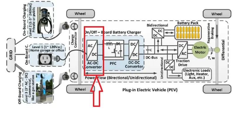
Fig -> AC – DC Converter (On Board Charger)
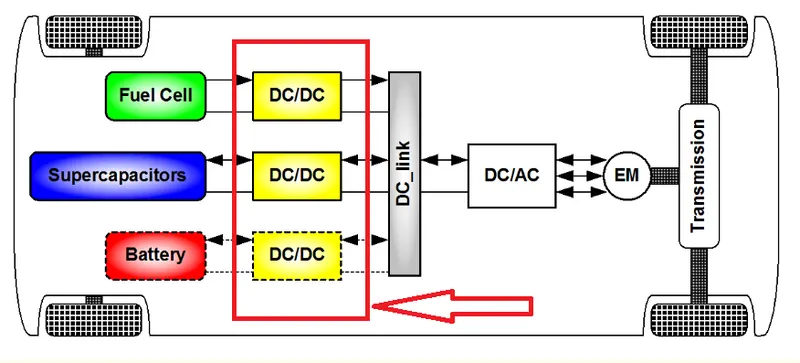
2)DC – DC Converter (Chopper): -
DC-DC converters can be used to interface the elements in the electric power train by boosting or chopping the voltage levels. By introducing DC/DC converters one can choose the voltage variation of the devices and the power of each device can be controlled.
The power of the DC/DC converter depends on the characteristics of the vehicle such as top speed, acceleration time from 0 to 100 Km/h, weight, maximum torque, and power profile (peak power, continuous power).
Importance of DC-DC converter :-
While DC/DC converters can be based on several different designs, the underlying function remains the same. A step-up converter, which turns a low-voltage input into a high-voltage output, or a step-down converter, which does the exact opposite.
In electric vehicles that use a DC motor, the running motor can use up to three times the voltage provided by the battery. With the help of the right converter, we can bridge this gap without having to use a larger, heavier battery.
Block Diagram of DC-DC Converter :-
3)DC – AC Converter (Inverter): -
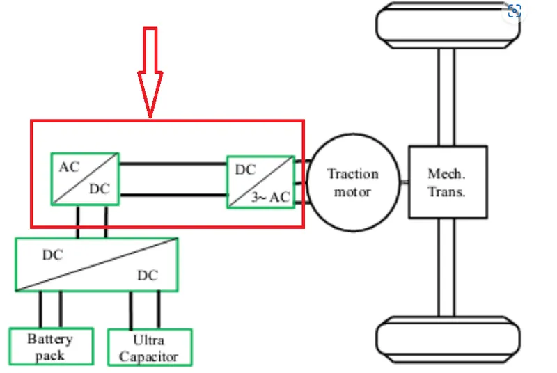
The DC/AC converter is required to convert the dc power to a suitable ac power for the electrical machine. The power output from battery pack (DC current) is converted using inverter to be used in electric motor (AC current).
Importance of DC-AC converter :-
The use of inverters can increase or decrease the power or torque of the motor by adjusting the amplitude of the signal.
It plays a significant role in capturing energy from regenerative braking and feeding it back to the battery. The key component is that it has a direct impact on on-road performance, driving range, and reliability of the vehicle also as a consequence of their weight and size.
The output voltage waveform of ideal inverters should be sinusoidal. However, the waveform of practical inverters is non-sinusoidal and contains certain harmonics.
Block Diagram of DC – AC Converter: -
------------------------------------------------------------------------------------------------------------------------
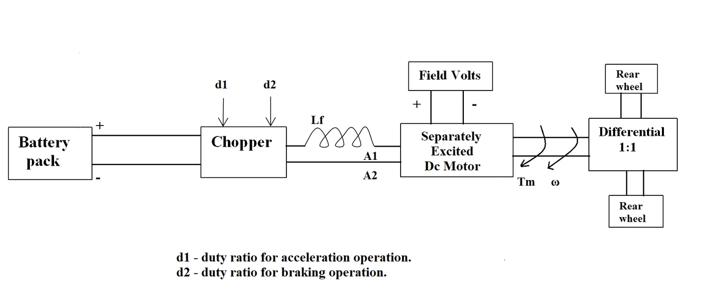
2) An Electric Vehicle's powertrain with 72V battery pack in shown in the diagram below. The duty ratio for acceleration operation is 'd1' and for the braking operation the duty ratio is 'd2'.
The other parameters of the electric vehicle is given below, Motor and Controller Parameters:
1) Rated Armature voltage= 72 V (2) Rated armature current= 400 A
(3) Ra= 0.5Ω (4)KΦ= 0.7 Volt second (5) Chopper Switching frequency= 400 Hz
The vehicle speed-torque characteristics are given by the below equation

What is EV steady state speed if duty cycle is 70%?
Aim) The Main is determine the Steadt State Speed For Given data
Given data :-(Motor and Controller Parameters)
Rated battery pack voltage (Vbat) = 72 V
Rated armature current(Ia)= 400 A
Ra= 0.5Ω,
KΦ= 0.7 Volt second
Chopper Switching frequency= 400 Hz
Duty cycle (d) %= 70 %
The vehicle speed-torque characteristics are given by the below equation:
-----------------(1)
From the given data steadt state speed is determinied by following steps :-
Step 1) from the battery pack volatge we can get the Vehicle voltage(Vv)
Vv= V bat * duty cycle(d)
=72*0.70
Vv=50.04 v
we know the Equation for Vehicle torque is given by:-
Tv=(Vv-W*kΦ)*KΦ)/Ra
Where;
Tv = vehicle tarque
Vv=vehicle voltage
KΦ=Flux constant
W=Speed of moter (rad/sec)
Ra=Resistance of Armature
Substituting all these values in equation, we get:
Tv=(50.4-W*0.7)0.7*0.5)----------------(2)
Tv=70.56-0.98W
Compare the both eqn(1) and eqn(2) then we get
70.56-0.98W=24.7+0.0051W²------------(3)
Since from quadratic equation,(3)
To solve the above eq we have to apply roots for qudratic equatation formula
W=-b+sqrt(b²-4ac) and W=-b-sqrt(b²-4ac)
W=(-0.98+sqrt(0.98²-4*0.0051*45.8600) and
W=(-0.98-sqrt(0.98²-4*0.0051*45.8600) then we get the values as
W= 38.85 rad/sec and W =-230.95 rad/sec
We take the positive value; then W=38.85 rad/sec
Conclusion :-
Steady state speed of vehicle for 70 % duty cycle = = 38.85 rad/s
------------------------------------------------------------------------------------------------------------------------
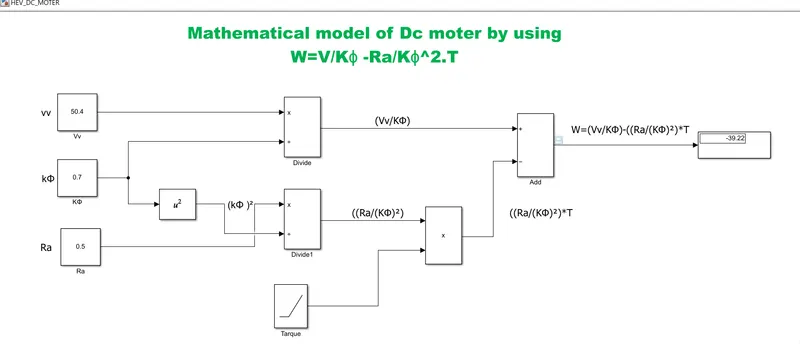
3. Develop a mathematical model of a DC Motor for the below equation using Simulink.
ω=V/Kϕ -Ra/Kϕ^2.T
Aim:-)The main is to create mathematical model of a DC Motor using simulinkof eqatation(ω=V/Kϕ -Ra/Kϕ^2.T)
from the above we can get the data
Vv=50.4v
Ra= 0.5Ω,
KΦ= 0.7 Volt second
Torque = increamnet signal assumed as ramp signal
For creating the Simulink model we are using the following blocks :-
Constant block:- To return the output signal as constant
add:- To return the output signal as addition of inputsignal
ramp:- To return the output signal as ramp signal of input value
product:-To return the output signal as product of input signals
square:-To return the output signal as square of input signals
display:- To return the output signal as in display
viewer Scope :- For Getting the output plot
Simulink Model :-
Scope:-
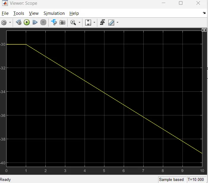
>>From the above scope we can observe that the the "W'' values is gets decresed beacuse in given eqn the -ve part gets a higher value.
>> Due to this reason the''W" values is getting -39.22 .we can obsrve this value in model display block as weel as in scope also .
Conclusion :-The Mathematical model of a DC Motor for the given equation using Simulink is created
------------------------------------------------------------------------------------------------------------------------------
4. Refer to the blog on below topic:
Induction Versus DC brushless motors by Wally Rippel, Tesla
Explain in brief about author’s perspective.
Aim) The main is to brief explanation of author'sprespective using below link
Link:- https://www.tesla.com/blog/induction-versus-dc-brushless-motors
Brief explanation of author'sprespective:-
In the beginning, the author describes the dominance of Internal Combustion Engines (ICE) in the world of automobile industry and also discuss different types of engines. He explains that all engines were similar and it was up to the user to select according to their requirement. He also speaks about induction motor and brushless DC motors and presents his view that these two technologies will be widely used for the coming years.
Then he explains the working of both 3-phase induction motor and a brushless DC motor.
Now the author has done comparison between these two technologies and stated some advantages and disadvantages of each.
3-phase Induction Motor:-
The technology behind the induction motor is that it basically uses a 3-phase induction motor which was invented by Nikola Tesla sometime before 1889. Unlike the DC brushless rotor, the induction rotor has no magnets just stacked steel laminations with buried peripheral conductors that form a “shorted structure.” Currents flowing in the stator windings produce a rotating magnetic field that enters the rotor. In an Induction motor current interacts with the Magnetic field generated by the stator to produce a force which is required for rotor torque.
When a 3-phase induction motor is connected to utility type 3-phase power, torque is produced at the outset. The fact that induction motors are directly compatible with conventional utility power is the main reason for their success.
Advantage:-
The induction motor does not have any magnets and in this the B field is adjustable. The motor has the ability to start under load and there is no need of an inverter. In an induction motor B field is proportionate to V/f (Voltage to frequency).
This technology is used to reduce the magnetic losses and conduction losses, due to which efficiency will remain at maximum peak. This all leads to increasing the performance, induction motor is very useful and efficient for high performance.
Disadvantage:-
An induction motor cannot operate from DC Voltage it always requires an AC voltage supply. In an induction motor, the Shaft speed is proportionate to line frequency. Hence, when used with utility power they are constant speed machines.
When operated from utility power, they have limited starting torque and somewhat limited running peak torque capabilities, when compared to DC-type machines.
DC Brushless Motor:-
With brushless machines, the rotor includes two or more permanent magnets that generate a DC magnetic field (as seen from the vantage point of the rotor). In turn, this magnetic field enters the stator core (a core made up of thin, stacked laminations) and interacts with currents flowing within the windings to produce a torque interaction between the rotor and stator.
As the rotor rotates, it is necessary that the magnitude and polarity of the stator currents be continuously varied – and in just the right way such that the torque remains constant and the conversion of electrical to mechanical energy is optimally efficient. The device that provides this current control is called an inverter. Without it, brushless motors are useless motors.
The author also said that a brushless DC motor produces no starting torque when directly connected to fixed frequency utility power. They really need the aid of an inverter whose “phase” is maintained in step with the angular position of the rotor.
Advantage:-
The advantage of DC Brushless Motor is that there is low heat generation in the rotor and its cooling capacity is better as compared to Induction Motor. Also, peak point efficiency is generally higher for this drive.
The DC brushless drive can also operate at unity power factor, whereas the best power factor for the induction drive is about 85%.
This means that the peak point energy efficiency for a DC brushless drive will typically be a few percentage points higher than for an induction drive.
Disadvantage:-
As Machine size grows, the magnetic losses increase proportionately and part load efficiency drops. Permanent magnets are expensive and difficult to handle due to very large forces that come into play when anything ferromagnetic gets close to them.
Brushless DC motor have some advantages like: much less rotor heat is generated with the DC brushless drive. The peak point energy efficiency for a DC brushless drive will typically be a few percentage points higher than for an induction drive.
Some disadvantages of Brushless DC motor are: as machine size grows, the magnetic losses increase proportionately and part load efficiency drops.
Permanent magnets are expensive and difficult to handle due to very large forces that come into play when anything ferromagnetic gets close to them.
In the end, the author couldn't choose which drive is better than the other but makes it clear that DC Brushless motor drives will likely continue to dominate in the Hybrid and upcoming Plug-in hybrid markets and induction motor drives will likely maintain dominance for the high-performance pure electric.
Conclusion:-The Brief of author'sprespective is explaned
__________________________________________________________________________________________
Results :-
1)Types of Power converters used in Elctrical vehicle and Hybrid Elctrical vehicle are explained.
2)Steady state speed of vehicle for 70 % duty cycle = = 38.85 rad/s
3)The Mathematical model of a DC Motor for the given equation using Simulink is created
4)The Brief of author'sprespective is explaned
__________________________________________________________________________________________________________________________________________________________________________________________________(The End)_________________________________________