Project 2 @ SOC % and Heat measuring by using Simulink Tool
***PROJECT***
Contents of the project:-
1)Aim of the project
2) Heat generation and SOC estimation techniques explanantion
3)Simulink model
4)Summery
5)Conclusion.
Aim of the project:-
The Main Aim is to determine the (a) The max heat generation of the battery and (b) SOC of the battery at 2 *104second of the battery operation By suing Given data with help of MATLAB /SIMULINK tools.
Heat generation and SOC estimation techniques explanantion:-
Heat Generation :-
If cells or batteries get too hot, they can rupture or explode. And Lithium and Lithium-ion cells/batteries can catch on fire when they rupture, creating even more of a safety hazard.
To ensure safe operation over the entire intended operating range of a cell or battery, it is crucial that the battery engineer understands the fundamentals of internal heat generation and be able to calculate the expected adiabatic temperature rise of a cell or battery under any operating condition.
Heat generation Sources:-
The following sorces are basically caused heat inside the battery pack.
-->Cell temperature
-->Ambient Temperature
-->State of charge
--> C-rate percentage
-->Internal Resistance
-->Number of Cycles used
--> Cell Electrochemistry.
Types of heat:-
Basically in battery companent the heat will be classified into Two types
1)Joule Heat:-
When a current is flowing through a resistance, there is heat dissipated in the resistor. This heat dissipation is called joule heating. Joule heating is also known as ohmic heating.
This is determined by using the Ohm's law as followes:-
From ohm’s Law,
                                 V = IR  --------------(1)
where,
V= Voltage
I = Current
R= Resistance
Power:-
power (p) = V *I

v= Voltage
I = Current


but we know V = I * R

Then,

Power p = I²* R-----------------------(2)

wehere,
p= power
I = Current
R= Resistance
Now ,
Joule heat = Power * time

 we know  power (p) = I² * R

then
Joule heat = Power * time

Joule heat = I² * R * t--------------------------------(3)

Where,
H = Joule Heat
I = Current
R = Resistance
t = Time
2)Entopic Heat:-
This Entopic heat is defined as The rate of change of "OCV" (Open Circuit Voltage) with respect to Temperature.
It is measured in joules/kg/ kelvin.
The increase in Entopic heatof a system( dS):-
Entopic heatof a system( dS)

              dS = δQ/ δT

where,

δQ = heat transfer
δT = The absolute temperature.
Therefor ,
Total Heat generated By battery = Joule Heat +Entopic HeatEstimation of SoC:-
State of Charge :-
It is the real-time or actual capacity of the battery compared to its full capacity.
It is measured in terms of percentage (%).
Let us consider If battery 100% SoC means the battery is fully charged to its capacity, and 0% SoC means it’s fully discharged.
State of charge (SOC) is the level of charge of an electric battery relative to its capacity.
The units of 'SOC' are percentage points (0% = empty; 100% = full).
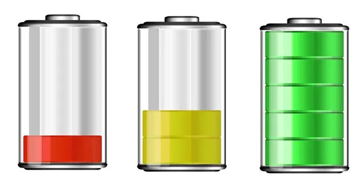
SOC= 20 % SOC= 40 % SOC = 100 %
The SoC is estimated basically using following 2 Methods:-
1)Voltage Transilation Method:-
This Voltage Transilation method Is determine the SOC by using the battery "Open Circuit Voltage (OCV)".
Voltage translation method is the least accurate method to do so, because as the lithium ion charge-discharge voltage cycle shows, the voltage is largely flat for a large region of the cycle; therefore, it does not give an accurate SOC.
Formula:-
Voltage Transilation Method:-


         SoC % =  Soc % Full / Number of parameters used for determianantion of SoC
2)Colomb Couniting Method:-
The Coulomb counting method counts the charge of the battery through current sensing, measuring how much current is flowing into the battery and how much current is flowing out of the battery.
Current is continuously monitored. Most all low-cost electronic products use the Coulomb counting method, as it is less expensive than the other more precise methods.
Formula:-
SOC Formulae :-

           z(t)= Z(0) + { I(t) / Cn) dt}


where ,
Z(t)= State Of charge in %
Z(0)= Initial State of charge in %
I(t)= Instancous Current at time t
Cn = Capacity of battery in Ah
dt= Step time
a)MAximum HEat generated by the Battery
Given data:-
From the formulae :-
Heat generated by battery pack = Joule heat + Entropy heat
Where,
Joule heat = I² R t
Entropy heat = 2(Joule heat)
therfore ,
Heat generated by battery pack = I² R t+ 2(I² R t)
Heat generated by battery pack = 3(I² R t)-----------------------(A)
from the given data,
Maximum current = -0.896 A
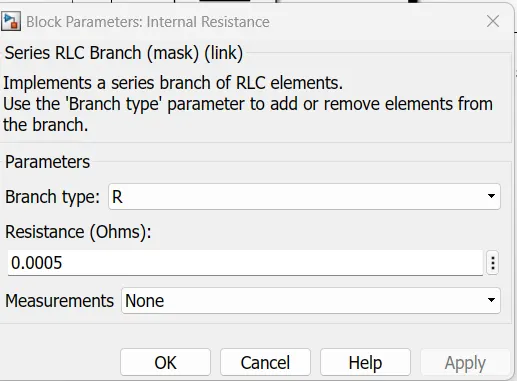
Resistance = 0.5 mΩ = 0.0005 Ω
time = 120sec = 0.03333333 hrs
From eqn (A)
Heat generated by battery pack = 3(I² R t)
= 3 * (0.896)² * (0.5)* 0.03333333
=48.166 mJ
Heat generated by battery pack =48.16 mJ
Therefore,
Maximum Heat generated by battery pack =48.16 mJ
Simulink model :-
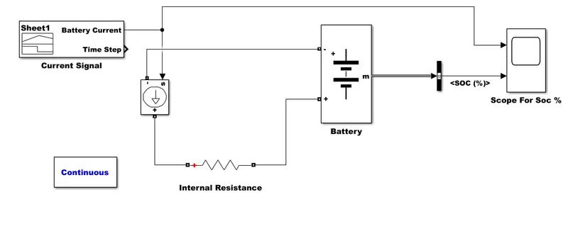
For creating the Simulink model we are using the following blocks:-
- Signal Builder :- To Give the Signal to As input to the Other blocks.
- Controlled current source:-Converts the Simulink input signal into an equivalent current source. The generated current is driven by the input signal of the block.
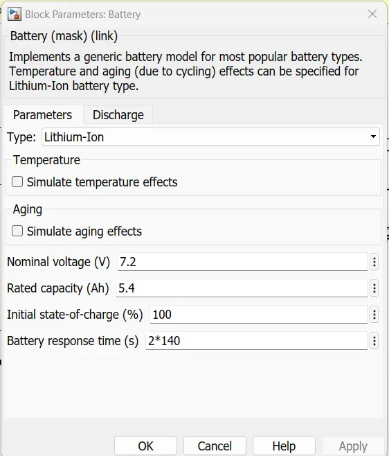
- Battery:- Implements a generic battery model for most popular battery types. Temperature and aging (due to cycling) effects can be specified for Lithium-Ion battery type.
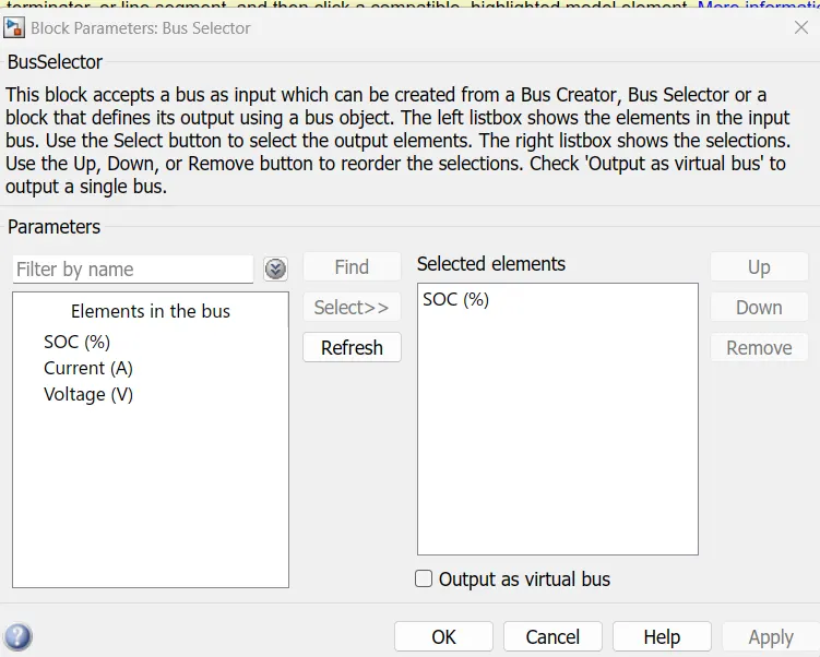
- Bus selector:-This block accepts a bus as input which can be created from a Bus Creator, Bus Selector or a block that defines its output using a bus object.
- Series RLC branch:-Implements a series branch of RLC elements. Use the 'Branch type' parameter to add or remove elements from the branch.
- Powergui:-Set simulation type, simulation parameters, and preferences.
g.Scope:-To plot the output signals in graphical view
Procedure :-
>>For this model firstly we have to add the Excell file for Signal Builder block by using the Below steps
>> for adding the Excell file double cilck on the Signal builder Block
>> Signal Block Klink :-Signal_sheet.xlsx
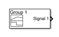
>>Then a new windoe will open as followes
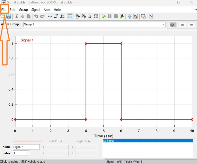
>> Now click on the File icon
>> After select the the import file from option
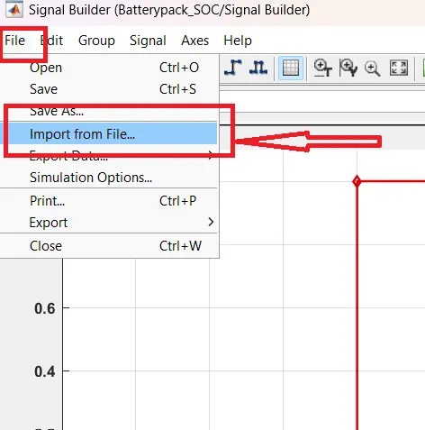
>> After another windoe will open as followes
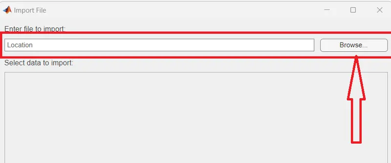
>>From this windoe brose the reqired Excell file
>> Then another windoe will open after extract the file as followes
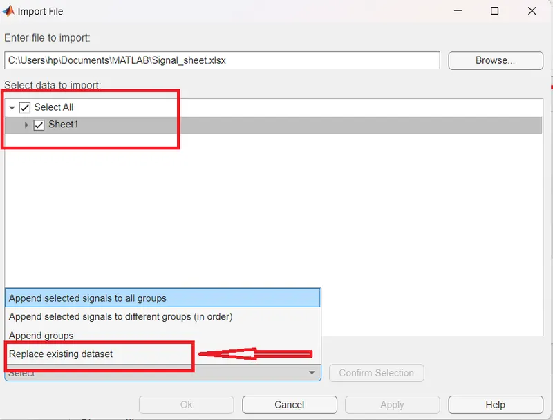
>> Now check mark the name of our excell aheet and
>> Select the option below as Replace the existing data sheet
>> After click on the Confirm selection
>> After that click on the apply button.
>>After complete this process we get the windoew as followes.
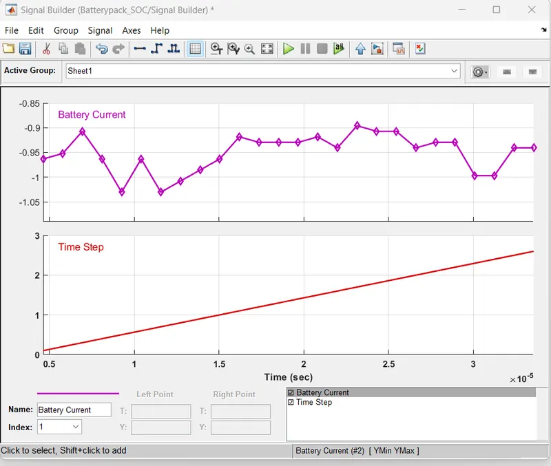
>> After completeing this process
>> this signal Bulder output is given to the Controlled Current source block
>>From this current controlled source block is and battery both are connected in sereis in between A resistance is added by using Series RLC branch block.
Battery parameter block :-
Series RLC brance select only "R " branch with following parameters
>> After SOc will be getting the scope by using the bus selector Block by selecting the signal as SOC%
Bus Selector Parameter block:-
>> After thiis Soc will plotted by using the Scope Block.
Results Scope :-
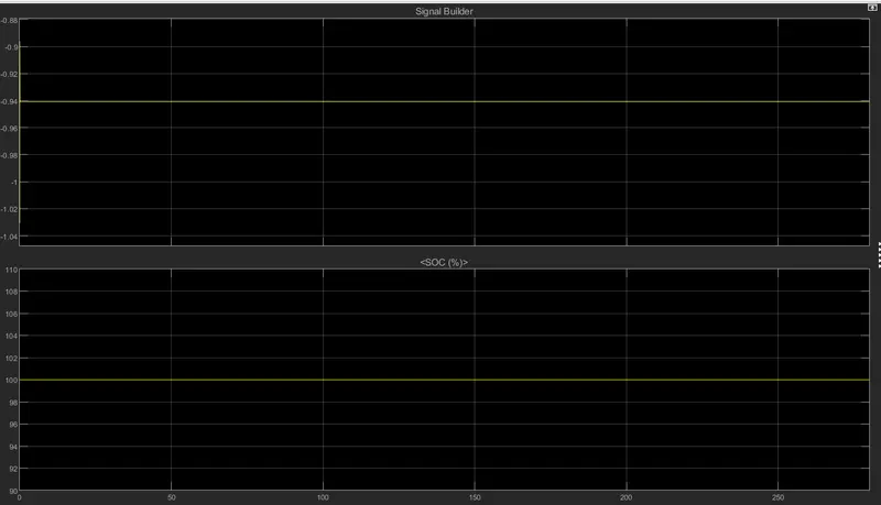
>> From the Above graph we consiste two parameters graphical view
Top Plot (Signal Builder plot)
>> From This grapph we can says the the given drive cycle is consisites a -ve cureent in always
>>And this value is moslty from -1.112 Amps to -0.868 Amos
>>maximum Current is 0.868 amps
>>This means this car cgetting the regenrative mode.
Bottom plot (SOC %):-
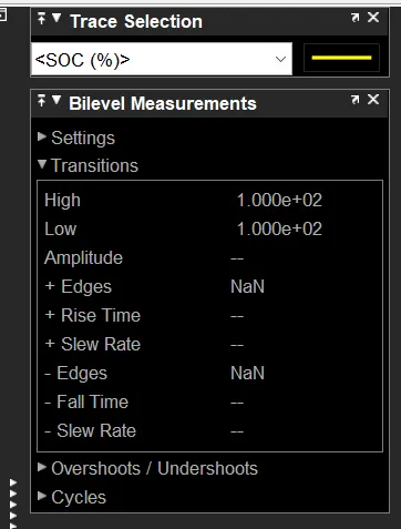
>>From the Grapgh we can conclude that The SOC% is always 100 %
>>because the vehicle in regerative breaking mode
>>In this Mode The Battery gets Charged always
>>dew To this reason The Soc % is Always 100 %
Summery:-
learning objectives :-
a)the outcomes from this project are Knowing about Heat generatin finding In battery packand Also About Soc measuring methodolagies for the battery pack.
>> From this project is we can learn this project while the Vehicle is regerave mode then the current as in negative direction hence the Battery gets charged Soc % ins 100 %.
Conclusion :-
We can conclude that The requirements for this projects are
- The max heat generation of the battery is 48.16 mJ
- The SOC of the battery operation is 100 % (Simulink model is also created and attached)
and also The requirement files are uploaded
----------------------------------------------------------------------------------------------------------------------------------------------