Project-1: Powertrain for aircraft in runways
PART -A
1. Search and list out the total weight of various types of aircrafts.
Aim) The main aim is list out the total weight of various types of aircrafts.
Aircraft:-
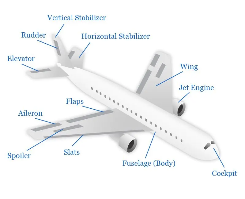
An aircraft is a vehicle that is able to fly by gaining support from the air. It counters the force of gravity by using either static lift or by using the dynamic lift of an airfoil, or in a few cases the downward thrust from jet engines.
An airplane is a , fixed wing aircraft that is propelled forward by thrust from a jet engine, propeller or rocket engin. Airplanes come in a variety of sizes, shapes, and wing cinfigurations.
The broad spectrum of uses for airplanes includes recreation, transportation of goods and people, military, and research. Worldwide, commercial aviation transports more than four billion passengers annually on airliners and transports more than 200 billion tonne kilometers of cargo annually, which is less than 1% of the world's cargo movement.
Most airplanes are flown by a pilot on board the aircraft, but some are designed to be remotely controlled or computer controlled such as drones.
DIfferent aircraft image is attached below :-
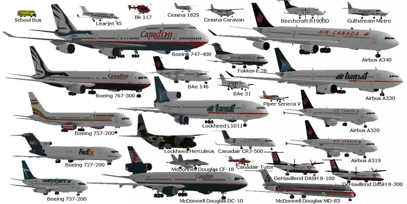
The aircrafts weights are classified in to different ways and those are followes :-
Manufacturer's Empty Weight(MEW):-
It is the weight of the aircraft "as-built" and includes the weight of the structure, power plant, furnishings, installations, systems, and other equipment that are considered an integral part of an aircraft. This excludes any baggage, passengers, or usable fuel.
Zero-fuel weight(ZFW):
This is the total weight of the airplane and all its contents (including unusable fuel), but excluding the total weight of the usable fuel on board. As a flight progresses and fuel is consumed, the total weight of the airplane reduces, but the ZFW remains constant. Maximum zero fuel weight (MZFW) is the maximum weight allowed before usable fuel and other specified usable agents (engine injection fluid, and other consumable propulsion agents) are loaded.
Operating Empty Weight(OEW):-
It is the basic weight of an aircraft including the crew, all fluids necessary for operation such as engine oil, engine coolant, water, unusable fuel, and all operator items and equipment required for flight but excluding usable fuel and the payload.
Payload:-
It is the carrying capacity of an aircraft. It includes cargo, people, extra fuel. In the case of a commercial airliner, it may refer only to revenue-generating cargo or paying passengers.
Maximum Take-off Weight(MTW):-
This is the maximum weight at which the pilot of the aircraft is allowed to attempt to take off.
Regulated Take-off Weight(RTW):-
Depending on different factors (e.g. flap setting, altitude, air temperature, length of runway), RTOW or maximum permissible take-off weight varies for each takeoff. It can never be higher than MTOW.
Maximum Landing Weight(MLW):-
This maximum weight at which an aircraft is permitted to land.
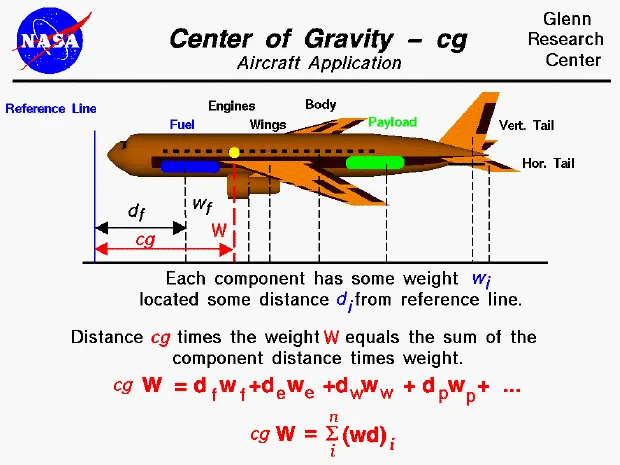
The following image depicts takeoff weight components-
Maximum Ramp/Taxi Weight(MRW/MTW):-
It is the maximum weight authorized for maneuvering (taxiing or towing) an aircraft on the ground.
Aircraft Gross-Weight:-
It is the total aircraft weight at any moment during the flight or ground operation. This decreases during the flight due to fuel and oil consumption.
The below figure is a rough estimation of weight parameters for different aircraft.
Total weights of various Types of Aircraft:-
The aircraft gross weight (also known as the all-up weight) is the total aircraft weight at any moment during the flight or ground operation. An aircraft's gross weight will decrease during a flight due to fuel and oil consumption.
This is the weight in an operational condition (with engine oil, hydraulic fluid, unusable fuel in the tanks and some other misc. items), zero cargo, with minimum crew. The minimum weight at which the aeroplane can fly.
Excel Link :- AIRCRAFT_WEIGHTS.xlsx
MTOW:- Maximum Takeoff Weight
MLW:-Maximum Landing Weight
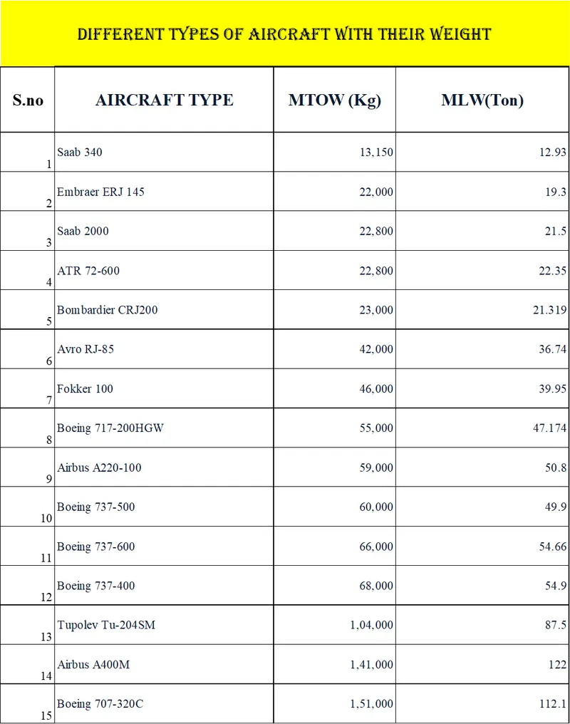
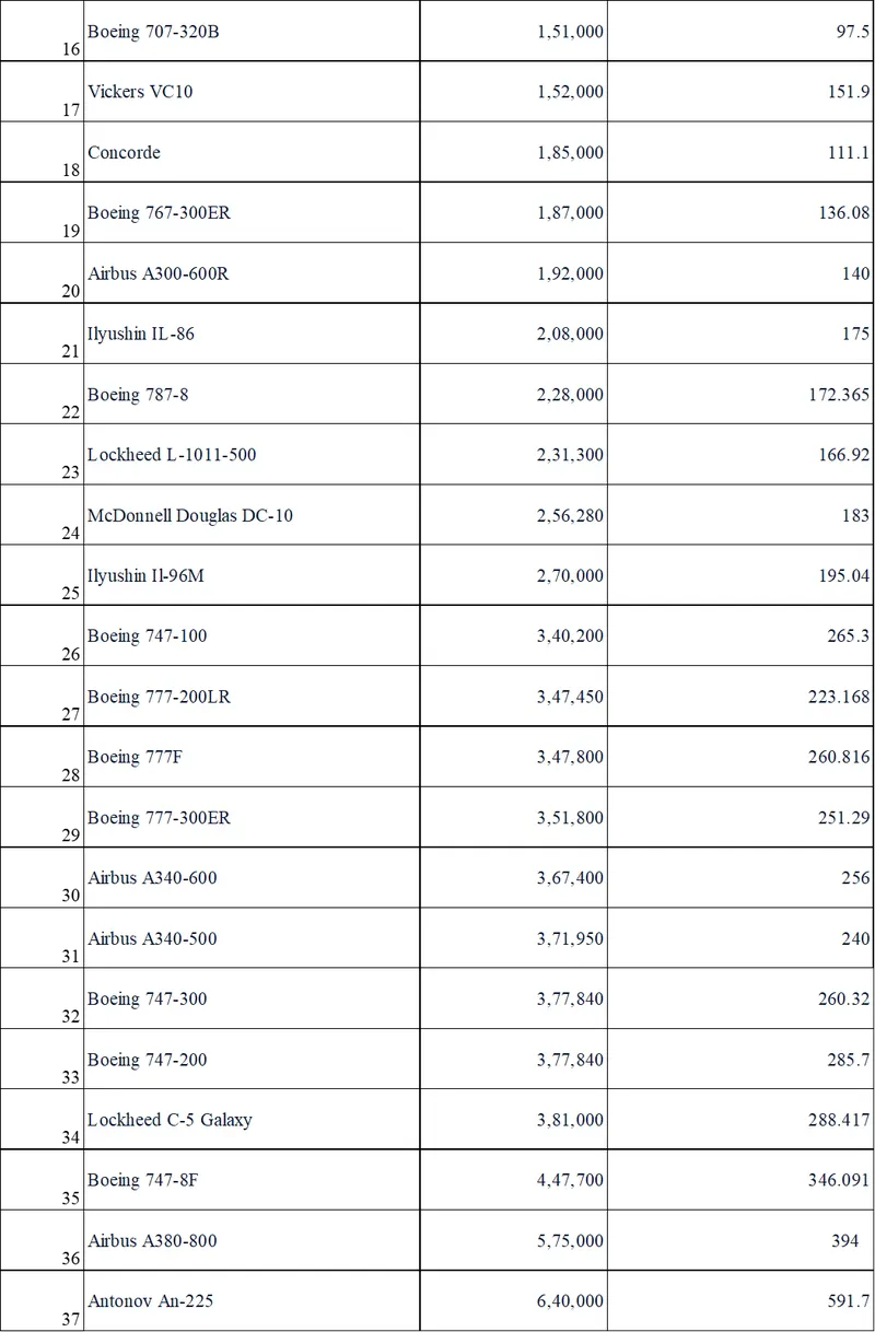
weight clasification chart is attached below :-
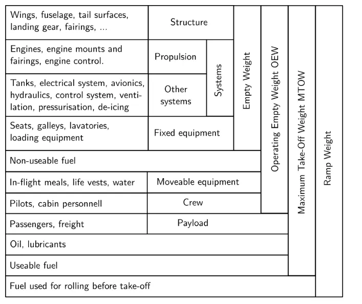
________________________________________________________________________________
2. Is there any difference between ground speed and air speed
Aim) Explain the difference between ground speed and air speed
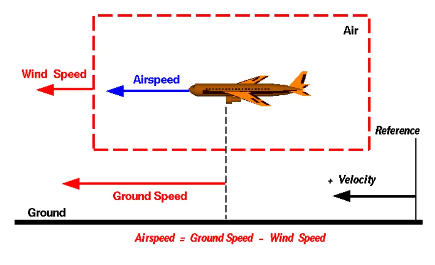
Ground speed :-
It is the airplane's speed relative to earth's surface. One thing that should be noted here is that it’s its horizontal rather than vertical speed – an aircraft climbing completely vertically would have a ground speed of zero.
Air speed:-
It is the airplane's speed relative to the air it is flying in. Air speed is what determines whether there is enough airflow around an aircraft to make it fly.
There are three types of air speed:-
a)Indicated air speed :-
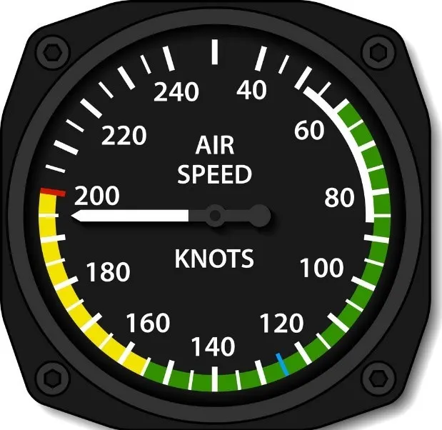
It is an air speed that is calculated directly off an aircraft’s pitot-static system. It’s the calculated off the aircraft’s dynamic pressure.The difference between its total pressure and static pressure. The dynamic pressure depends not only on the aircraft’s speed, but also on the density of the air it is flying in. As such, the higher the aircraft flies – and the lower the air density as a result .The bigger the difference between indicated and true air speed.
b)Caliberated air speed:-
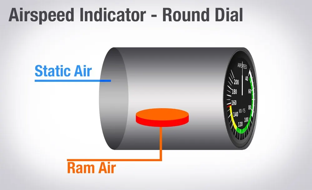
It is indicated air speed adjusted for a variety of errors.Just as an example, one of the things it’s adjusted for is the flap position. The reason for that is that at different flap positions, air flows differently around the pitot-static system and affects the indicated airspeed readings.
c)True air speed :-
It is the actual speed at which an aircraft is moving relative to the air it is traveling in. It’s calibrated airspeed adjusted for the the exact conditions (altitude, air temperature, etc.) that the aircraft is flying in.
Relation between Ground and airspeed:-
The relationship between airspeed and ground speed is fairly simple. Ground speed is simply the sum of airspeed and wind speed. If the aircraft is flying in the same direction as the wind is blowing, the aircraft experiences tailwind, and its ground speed is higher than its airspeed. On the other hand, if the wind is blowing against the direction the aircraft is traveling in, the aircraft experiences headwind, and its ground speed is lower than its airspeed.
To give you an actual example, imagine an aircraft that cruises at an airspeed of 500 miles per hour that has to cover a ground distance of 2,000 miles.If there is no wind at all, then both the aircraft’s airspeed and ground speed would be the same 500 miles per hour, and the aircraft would reach its destination in four hours.
If there was a 100 miles per hour headwind – wind blowing against the aircraft’s direction of travel – the aircraft would still be traveling at an airspeed of 500 miles per hour. However, its ground speed would be just 400 miles per hour (100 miles per hour slower than its airspeed). And as such, it would take the aircraft five hours to reach its destinations.
Finally, if there was a 100 miles per hour tailwind – wind blowing in the same direction as the aircraft’s travel – the aircraft would still be traveling at an airspeed of 500 miles per hour, but its ground speed would be 100 miles faster.And, at 600 miles an hour, the aircraft would reach its destination in just three hours and twenty minutes.
The above is the reason why some flights go “out of their way” to avoid headwinds or catch tailwinds. And, why some flights might appear to be traveling at “supersonic speeds,” even though their airspeed – the speed that would actually matter in determining whether or not the flight truly is supersonic – is subsonic.
For pilots, both airspeed and ground speed are very important. While the first of those helps them make sure they are flying fast enough to take off, not to stall, and so on, the second one helps them figure out how long it will take them to get from one place to another.
On the other hand, if you are a passenger, you will only need to be concerned about the ground speed as that will tell you how fast are you flying from your origin to your destination – how fast you will be able to get to your meeting, meet your relatives, or do whatever else the reason for your travel might be.
|
AIR SPEED |
GROUND SPEED |
|
Speed relative to air |
Speed relative to ground. |
|
Measured quantity. Using Pitot tube. |
Calculated quantity. (Air speed + Wind velocity) |
The speed an animation by NASA is attached below:-
Link :- Animated Relative Velocities (nasa.gov)
________________________________________________________________________________
3)Why is it not recommended to use aircraft engine power to move it on the ground at Airport?
Aim)The main aim is explain about Why not use aircraft engine power to move it on the ground at Airport
Reason :-
Generally, it is not recommended to use aircraft engine power to move it on the ground at the airport because there are some disadvantages like the engine power will create a large noise, and there will be fuel losses while moving the aircraft on airport. The use of engine thrust near terminals is restricted due to the possibility of jet blast damage.
If we talk about safety then during taxiing, aircraft travel slowly. This ensures that they can be stopped quickly and do not risk wheel damage on larger aircraft if they accidentally turn off the paved surface. Taxi speeds are typically 30 to 35 km/h.
For movement on the ground the aircraft uses it own engine power, which is called taxing.
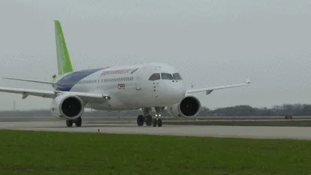
Although many aircrafts are capable of moving in backward using reverse thrust, as result the jet blast or prop wash might cause damage to the terminal building or equipment. Engine close to ground may also blow sand and debris forward and then suck them into the engine, causing damage to the engine.
Therefore there are pushback trucks in the airport. A pushback truck lifts the front weel of the aircraft, their role in most airports is to move the aircraft away from the parking spot on to the taxiways, which is called towing.
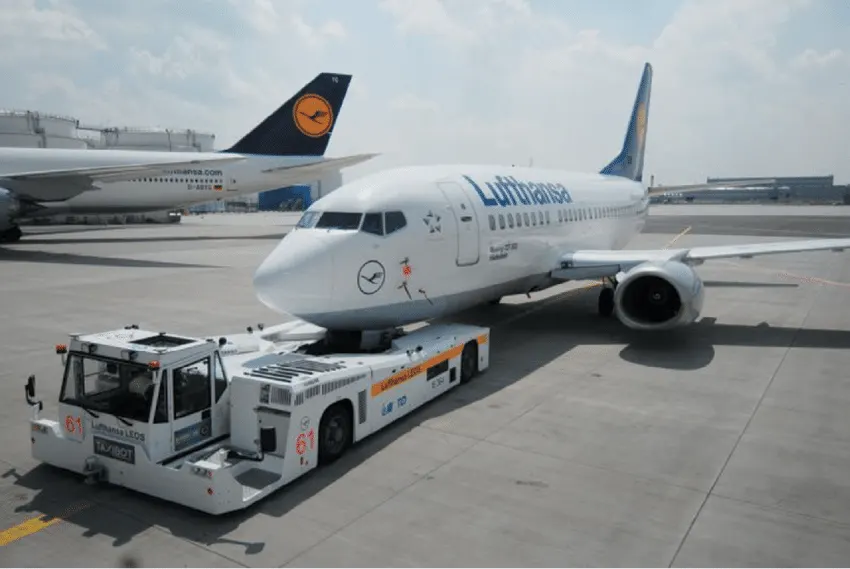
Unwanted consequences mainly arising from the unintended movement of the aircraft during engine running.
i) Effectively a loss of control can happen, especially during high power engine running. Damage can occur to the aircraft itself, other aircraft nearby or to airside structures.
ii) There is a risk of injury to ground support personnel who may be in relatively close proximity to the aircraft.
iii) It is easier for truck driver to see the surroundings better than the pilot sitting in the cockpit with limited window. The pushback driver knows the airport better than the pilot
iv) It also saves fuel. virgin Atlantic had proposed a new system in which pushback truck will move the aircraft all the way to runway to save fuel and reduce impact of environment.
v) The plane engines are very loud. When more than one plane will add up their sound, than it will not be pleasent for passangers and others near airport.
__________________________________________________________________________________________
4)How an aircraft is pushed to runway when its ready to take off.
Aim) The main aim to Explain the How aircraft is pushed to runway when its ready to take off
There are basically two type of pushings those are :-
Towing
b)T
a)Towing:- In the parking areas, where taxing the aircraft is not practical or is unsafe, such as moving aircraft in and out of mainteance hangars, or moving aircraft that are not under their own power or moving backward, then towing of aircraft is performed using the power of a specialized ground vehicle attached to or supporting the nose landing gear. The traditional method of allowing the ground vehicle to move an aircraft is to attach it to the aircraft nose landing gear by means of towbar.
As the pilot can't see what is behind the aircraft, steering is done by pushback tractor driver and depending on the aircraft type and airline procedure, a bypass pin may be temporarily installed into the nose gear to disconnect it from the aircraft's normal steering mechanism. Once the towing is completed, the towbar is disconnected and the aircraft can taxiing forward under its own power.
Fig --> Towing Vehicle
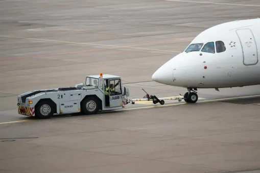
Fig:- plane Moving ina airport By using Towing vehicle
Taxiing :-
Taxiing is the movement of an aircraft on the ground under its own power while on the suface. The aircraft always moves following the yellow lines, to avoid collision with the surrounding buildings, vehicle or other aircrafts. The taxiing motion has a speed limit. Before making turn the pilot reduces speed further to prevent tire skids just like other vehicles. The reason for taxing is to reach the vehicle into runway or from runway to terminal.
Basically, taxing is used to towing or push-back where the aircraft is moved by a tug.
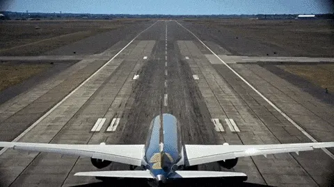
Image :- Taxing moment of plane
________________________________________________________________________________________
5) Learn about take off power, tyre design, rolling resistance, tyre pressure, brake forces when landing.:-
Aim) the main aim is to explain the take off power, tyre design, rolling resistance, tyre pressure, brake forces when landing.
Take off power:-
Takeoff is the phase of flight in which an aircraft leaves the ground and becomes airborne. For aircraft that take off horizontally, this usually involves starting with a transition and moving along the ground on a runway.
For light weight aircraft, usually full power is used during takeoff. Large transport catagory (airliner) aircraft may use a reduced power for takeoff, where less than full power is applied in order to prolong engine life, reduce maintenance costs and reduce noise emissions.
In some cases, the power used can then be increased to increase the performance. Before takeoff, the engines, particularly piston engines are routinely run up at high power to check for engine-related problems.
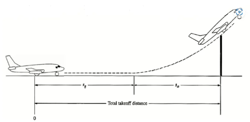
An airplane is motionless at the starting of a runway. This is denoted by location O. The pilot releases the brakes and pushes the throttle to maximum takeoff power, and the airplane accelerates down the runway. At some distance from its starting point, the airplane lifts into the air. The distance the airplane cover along the runway before it lifts into the air is called the ground roll (sg).
The total takeoff distance also includes the extra distance covered over the ground after the airplane is airborne but before it clears an obstacle of 50 ft for military aircraft and 35 ft for commercial aircraft. This is denoted by sa. The sum of sg and sa is the total takeoff distance.
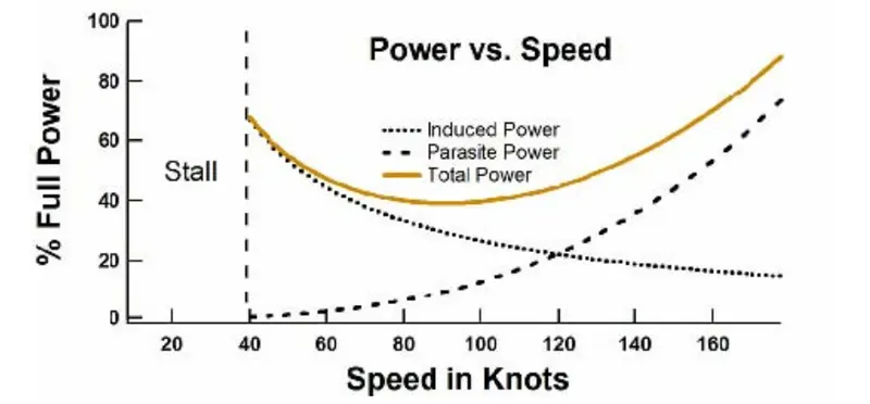
The bove Figure shows the "power curves" for induced power, parasite power, and total power (the sum of induced power and parasite power). Again, the induced power goes as 1/speed and the parasite power goes as the speed . At low speed the power requirements of flight are dominated by the induced power.
The slower one flies the less air is diverted and thus the angle of attack must be increased to increase the vertical velocity of that air. Pilots practice flying on the "backside of the power curve" so that they recognize that the angle of attack and the power required to stay in the air at very low speeds are considerable.
Tyre design :-
An aircraft tyre is designed to withstand extremely heavy loads while landing, take off, taxing and parking. The number of wheels required for aircraft increases with the weight of the aircraft, as the weight of the aeroplane needs to be distributed more evenly.
Engineers are challenged with designing tires with cool running, heat-resistant materials while simultaneously exceeding tire service requirements. Tire prototypes are put through rigorous tests that simulate cycles of landings, take-offs, and taxi operations. It is only after the tires pass all mandatory tests and meet the requirements of the aircraft manufacturer and airworthiness authorities that the tires are put into production
In aircraft applicatio Two types of tyre are used,
a)Bias-ply tyre
b)Radial tyre.
a)Bias-ply tyre:-
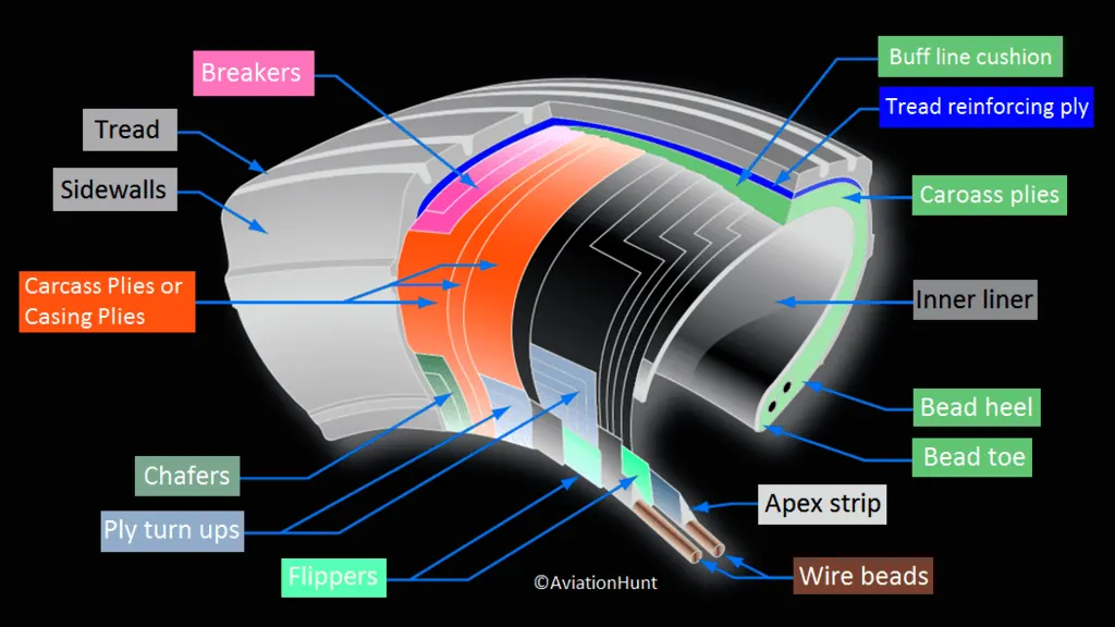
Bias-ply tires are popular choices for aircraft tires because of their durability and retreadability. The tire construction consists of the following components:
The cross section of bias tyre is shown below:-
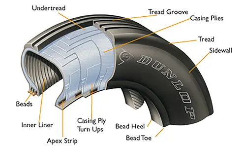
The parts of bias tire is explained below:-
Tread:-
The tread is made of rubber mixed with other additives to obtain the desired level of toughness, durability, and resistance to wear.
Sidewall:
The sidewall is a protective layer of rubber that covers the outer casing ply. It extends from the tread edge to the bead area.
Buff Line Cushion:-
The buff line cushion is made of rubber compound to enhance the adhesion between the tread reinforcing ply and the breakers or casing plies.
Breakers:-
Breakers are reinforcing plies of rubber-coated fabric placed under the buff line cushion to protect casing plies and strengthen and stabilize the tread area.
Casing Plies:
Alternate layers of rubber-coated fabric (running at opposite angles to one another) provide the strength of the tire.
Wire Beads:-
Hoops of high tensile strength steel wire that anchor the casing plies and provide a firm mounting surface on the wheel.
The outer edge of the bead that fits against the wheel flange is called the bead heel. The inner bead edge is called the bead toe.
Apex Strip:-
A wedge of rubber affixed to the top of the bead bundle.
Flippers:-
Layers of rubberized fabric that help anchor the bead wires to the casing and improve the durability of the tire.
Ply Turnups:-
The casing plies are anchored by wrapping them around the wire beads, thus forming the ply turnups.
Chafer:-
A protective layer of rubber and/or fabric located between the casing plies and wheel to minimize chafing.
Liner:-
In tubeless tires, the liner is a layer of low permeability rubber that acts as a built-in tube and restricts gas from diffusing into the casing plies. In tube-type tires, a thinner liner is used to prevent tube chafing against the inside ply.
b)Radial type:-
A typical radial tyre With their rigid belt, they provide increased landings and reduced rolling resistance. They have fewer components in their construction and are lighter than similarly sized bias ply tires.
The cross section of Radial tyre is shown below:-
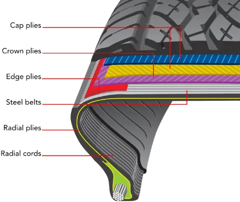
Components that differ from bias-ply construction as follows:-
Overlay:-
A layer of reinforcing rubber coated fabric placed on top of the belts to aid in high speed operation.
Belt Plies:-
A composite structure that stiffens the tread area for increased landings. The belt plies increase the tire strength in the tread area.
Casing Plies:-
As in bias-ply tires, the casing plies are layers of rubber-coated fabric. However, unlike those in bias plies that run at opposite angles to one another, radial plies run radially from bead to bead.
Chippers:-
The chippers are layers of rubber-coated fabric applied at diagonal angles that improve the durability of the tire in the bead area.
Rolling resistance:-
Rolling resistance sometimes called rolling friction or rolling drag, is the force resisting the motion when a body (such as a ball, tyre, or wheel) rolls on a surface.
It is mainly caused by non-elastic effects; that is, not all the energy needed for deformation (or movement) of the wheel, roadbed, etc., is recovered when the pressure is removed. Another cause of rolling resistance lies in the slippage between the wheel and the surface, which dissipates energy.
Formula for Rolling resistanec force is given by :-
Rolling resistance force Frr = urr * m * g
here,
urr= rolling resistance constant
m = total mass of the aircraft(Actual mass+Pay load) in kg
g = gravitational constant, that is 9.8 m/s^2 .
Tyre pressure :-
An aircraft tyre or tyre is designed to withstand extremely heavy loads for short durations. The number of tires required for aircraft increases with the weight of the aircraft, as the weight of the airplane needs to be distributed more evenly.
Aircraft tire tread patterns are designed to facilitate stability in high crosswind conditions, to channel water away to prevent hydroplaning, and for braking effect.
According to U.S. Federal Aviation Administration(FAA) Technical Standard Order TSO-C62c, the maximum allowable tire pressure loss is 5% per day.
Brake Forces When Landing:-
Fig-> Breaking System in aircraft
Stopping an aircraft landing at 180-200 mph requires a lot of braking force. To do this, the aircraft has brake unit on each of the wheels on the main gear assembly. On landing, pilots should use aerodynamic braking by applying extra back-pressure on the stick or yoke.
Extreme caution should be used when applying brakes at any significant speed, and only when the end of the runway is quickly approaching. Never step on the brakes to make a runway exit. Applying the brakes at too high a speed could burn the tires, wear out the brakes, or result in a ground loop or swerve.
Aircraft braking systems include followind data:-
Aircraft Disc Brake:
In the landing gear it is used to brake the wheels while touching the ground. These brakes are operated hydraulically. In most modern aircraft they are activated by the top section of the rudder pedals ("toe brakes").
In some older aircraft the bottom section is used instead ("heel brakes"). Levers are used in a few aircraft. Most aircraft are capable of differential braking.
Thrust Reverse: -
That allow thrust from the engines to be used to slow the aircraft.
Air Brake:-
It is dedicated flight control surface, that work by increasing drag.
__________________________________________________________________________________________
PART-B
6) (A)With necessary assumptions, calculate the force and power required to push / pull an aircraft by a towing vehicle.
Aim)The main aim is calculate the force and power required to push /pull an aircraft by a towing vehicle.
To push or pull an aircraft by a towing vehicle, 2 type of forces will act on that vehicle.:-
(i) Rolling resistance force
(ii) Aerodynamic drag force
Hill climbing force is negliza ble because vehicle moving on Ground only
Rolling resistance force(Frr) :-
Rolling resistance is the force resisting the motion when a body rolls on a surface. It is the friction force that is needed to be overcome to move a vehicle.
The kinetic energy of the wheels is partially converted into heat. The rolling resistance is proportional to the normal force perpendicular to the rolling wheel and is approximated by the rolling resistance coefficient urr.
Equation that can be used for the rolling resistance force is:-
Frr = µrr * m * g
here,
µrr= Rolling resistance co-efficient
m= Total mass of the vehicle (vehicle mass + payload) in kg
g = gravitational constant , that is 9.8 m/s²
Aerodynamic drag force(Fad):-
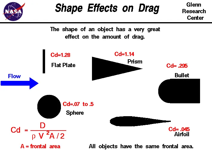
Aerodynamic drag force is the force which is required to keep a vehicle moving. There are two component of this force , one is shape drag (due to the shape of the vehicle) and another is skin friction (due to friction between air and skin of the vehicle).
When the vehicle moves the velocity of air near boundary is higher than the air surrounding. Both the tug and the aircraft will experience some aerodynamic drag.
Aerodynamic drag force Equation given belowL:-
Fad = (1/2) * ρ * V² * A * (Cd)
Here,
ρ = Air density, that is normally 1.25 kg/m³
A = Frontal area of the vehicle in m²
Cd_t = Air drag co-efficient of towing vehicle
Cd_a = Air drag co-efficient of aircraft
v = Velocity of the vehicle in m/s
Hill climbing force(Fhc) :-
Hill climbing force is the force needed to move the vehicle in up gradient.
Hill Climbing force equation is given below:-
Fhc = m * g * sinφ
Here,
m = Total mass of the vehicle(vehicle mass + payload) in kg
g = Gravitational constant that is 9.8 m/s²
φ = up gradient angle or inclination angle in radian(In this case up gradient angle(φ) = 0, as there is no inclination.)
Power(Pull / push) Calculation of Towing Vehicle-
Total Traction Force (Ft)=Frr +Fad+Fhc
The total power(Pt)=Ft.V
Let's assume the parameters:-
The mass of aircraft = 183700 Kg
The mass of towing vehicle= 50000 Kg
Total mass of the vehicle(m) = (50000+183700) = 233700 Kg
Towing vehicle fontal area(A) = 20 m²
speed of the vehicle(V) = 30 Km/hr = 8.333 m/s
For this case for towing vehicle for aircraft(µrr)= 0.013 (wheels on concrete)
In this case air drag co-efficient for towing vehicle(Cd_t)= 0.5
Air drag co-efficientfor aircraft or payload(Cd_a)= 0.045
Total Drag Coefficient (Cd= Cd_a+Cd_t)=0.045+0.5=0.545
In this case up gradient angle(φ) = 0 (Vehicle is moving on ground level)
Air Density (Kg/m3) (ρ)=1.25
Speed Of towing vehicle (v)= 15 Kmph
Finding the Forces acting the vehicle :-
Rolling Resistance Force(Frr) = µrr * m * g
=0.013 * (50000+183700) * 9.8 Frr=87192.261 N
Aerodynamic Drag Force(Fad) = (1/2) * ρ * V² * A * (Cd) = (1/2) * 1.225 * (2.778)^2 * 20 * (0.5+0.045)
Fad =5.91362 N
Therefore,
Total Required Traction Force(Ft) = Frr + Fad
=87192.261+5.9136
Ft =87198.17463 N
Total Traction Power(Pt)= (Ft * v) / 1000 Kw
=29824.894 * 4.166 Kw
Pt=363.325 Kw
The Towing vehicle (Pushor pull ) Power(KW)= 363.325 Kw
Excel calculation Link :-
Link:- AirCraft_forces_projects.xlsx
Excel Formet:-
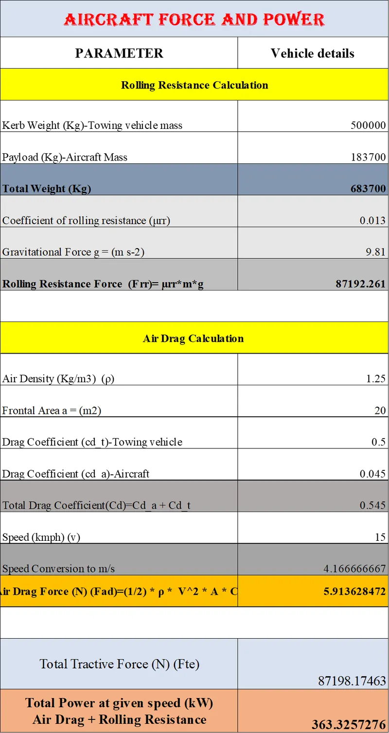
Conclusion :-
Total Required Traction Force(Ft)=87198.17463 N
The Towing vehicle (Pushor pull ) Power(KW)= 363.325 Kw
__________________________________________________________________________________________
6) (B) Develop the model for the calculated force and power using Simulink.
Aim) The main aim is to createthe simulinbk model for calculated force and power For Aircraft
To push or pull an aircraft by a towing vehicle, 2 type of forces will act on that vehicle.:-
(i) Rolling resistance force(Frr)
Frr = µrr * m * g
(ii) Aerodynamic drag force (Fad)
Fad=(1/2) * ρ * V² * A * (Cd)
For creating thi smodels following blocks are used:-
constant:-To writen the output signal as constant value
add:-To writen the output signal as Addition of input signals
product:-To writen the output signal as product of input signals
square:-To writen the output signal as aquare of input sigbnals
to workspace :-To writen the output signal in workspace
displace :-To writen the output signal in display
Simulink model :-
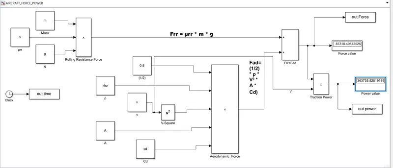
Model :- Simulink model
Procedure:-
Rolling resistanec force :-
>> Firstly we aasign the valuse of mass(m)and gravitationla constant(g) and Rolling resistanec constant (µrr) values by using "Constant '' block.
>> then after these three values are producted by using"Product" block.then the out put of reslling resisitnce force is obtained.
Aerodynamic force force :-
>> For thes force block i was assiging the values of frontel ares(A),Air density (rho), Drag coefficient (Cd) and velocity (v) By using the "Constant " Block.
>>After that i was square the velocity (v) value by using the square " block.
>> After that these total values are producted by using "Product"Block.
>>after these (rolling resistance force and Aerodynamic force) are added by usnig the "Add" block.
>>For power block we can multyply the total force with velocity block by using "product" block.
>>After the total force and total power valuse are displaed by using the "Display " block.
Rsults :-
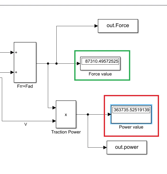
From the above display blocks
The Red one is Total power in watt=363735.52 watt
The green box is for force (N)=87310.495.
Conclusion :- The Simulink model for Aircraft Power and forces is created
___________________________________________________________________________________________________
7.(A) Design an electric powertrain with type of motor, it’s power rating, and energy requirement to fulfill aircraft towing application in Simulink. Estimate the duty cycle range to control the aircraft speed from zero to highest. Make all required assumptions. Prepare a table of assumed parameters. Draw a block diagram of powertrain. (Hint :DC7 Block)
Aim) The main aim is Develop a power train block of an towing vehicle (electric) in simulink.
Power Train Block digaram :-
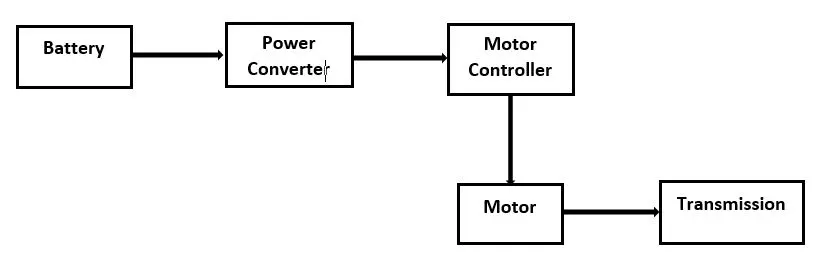
Flow Chart for powertrain in electrical vehicle :-
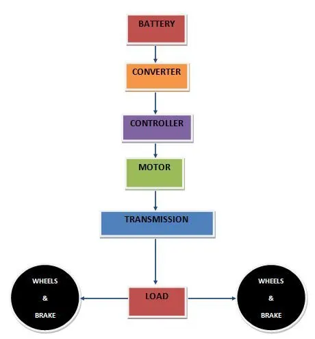
Electric Vehicles, consist of a battery, connected to an electric motor (either AC or DC) via an inverter and a motor controller.
As automotive batteries generally operate on DC current, while the gird operates AC, a converter is needed to transfer power to the battery.One of the key advantages of an EV is its much higher levels of energy efficiency.
Typically an EV will achieve a system efficiency of 80% from battery to wheel (roughly 60% from grid to wheel), while with a conventional IC engine it’s more like 15-25%. This is largely due to the fact that an IC engine is a “heat engine” (i.e. it has to burn fuel and produce heat to operate) and much of all that heat is simply wasted.
Requirement to fulfill aircraft towing application :-
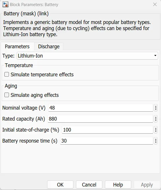
Battery:- (Rating per single battery)
Nominal voltage (V)=12 v
Rated capacity (Ah)=220
Initial state-of-charge (%)=100
Battery response time (s)= 30
Here the towing vehicle require high torque application so wer connecting the 4 batteries are arranged in series combination as we are using for .
So the overall
voltage( V) = 48v
current (I)= 880Ah
Assumes perameters:-
Based on the calculations done in 6(A).
Force (Ft) =87198.17463 N=87.198 KN
Power(pt)=363.325 kw
Eneregy= power ) *(time)
=363.325 * 0.00833333
=3.025 Kwh
v=4.166 m/sec
time = 30 sec =0.00833333 hrs
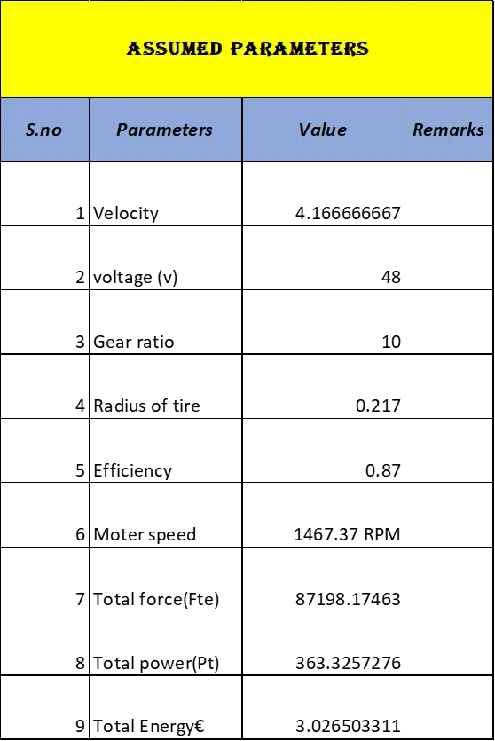
Assumed parameters :-
gear ratio=10
radius of tire =0.217 m
efficieny =87 %
Let us assume,
NOw Calculating the Speed of Moter in terms of Angular velocity (w)= (Rad/Sec):-
w = (G* V)/r
= (8*4.166)/0.217
w=153.58 Rad/sec
Speed in RPM:-
speed in RPM =w (Rad/ sec) *(60/2 Pi)
Speed w =153.58 *(60/6.28)
=806.451*95.5
Speed =1467.37 RPM.
Now to calculate the armature resistance of motor
Ia= V/ r
here ,
V= supply voltage =48 v
Resistance of battery=3.5 ohm
then,
= 48v/(4*3.5)
= 3.428A
Required torque (T) = F*r / G*η
here,
F = force at wheels
r = radius of wheel
G = gear ratio=10
η = efficiency
then, Torque
T = (87.198)*(0.217 )/ (10*0.75)
T= 25229.288 Nm
Here we consider the motor power of 380 kW to meet our load torque for towing operation.
Now the duty cycle by above data is 'Duty Cycle' = Output power / Input power
Po =output power,
Pi = Input power
'Duty Cycle' (D) =363.78kW/ 380 kW = 0.956
Duty Cycle' (D) = 95.6%
Design parameters Excel formet:-
Link :- AirCraft_forces_project (1).xlsx
. 
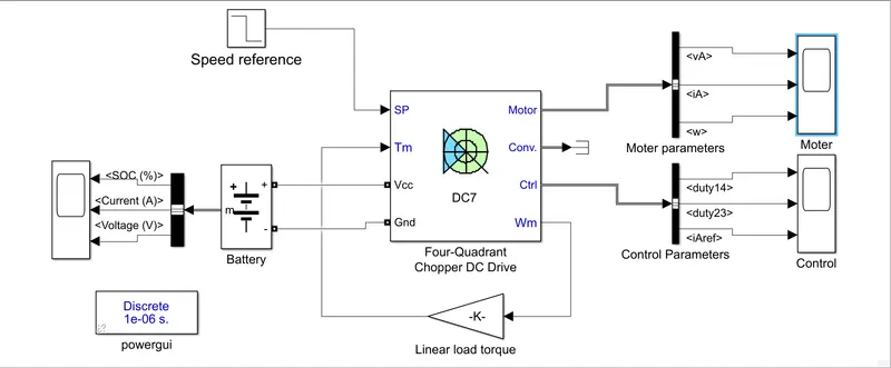
Creating the Simulink Model :-
For creating this model by using following blocks:-
Battery :- For giving the supply to Dc7 Chopper block
Step :- To give the input speed signal to the Dc7 Chopper block.
gain:- for giving the Feedback loop to the Chopper block as a torue block.
DC7_Four-Quadrant
Chopper DC Drive- For Dc machine and Control purpose of Toweing vehicle.
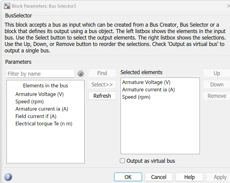
Bus selector :-This block accepts a bus as input which can be created from a Bus Creator, Bus Selector or a block that defines its output using a bus object. The left listbox shows the elements in the input bus.
Powergui :-This is selected discrete type with (1e-06)
Scope:- To plot the output signals.
Simulink model :-
Procedure:-
>> Firstly Dc7block chopper block is is arrnged with towing vehicle parameteras followes .
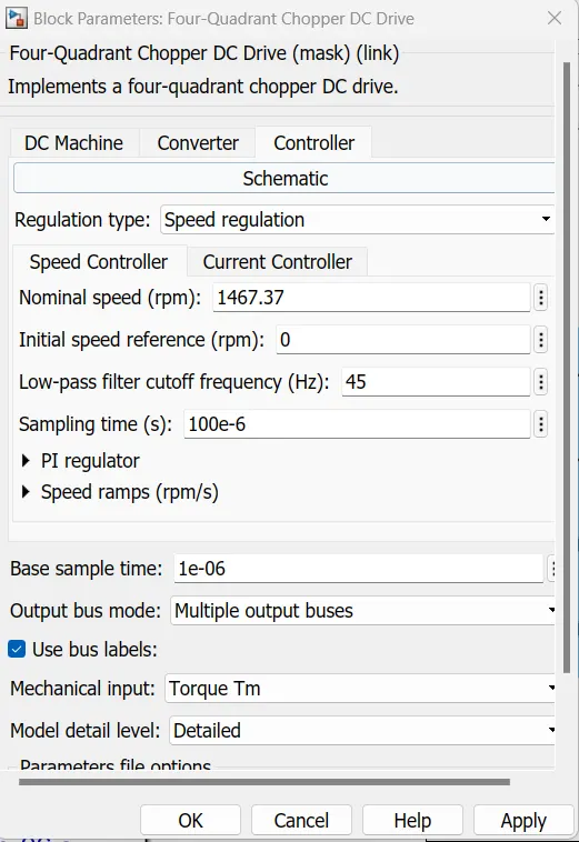
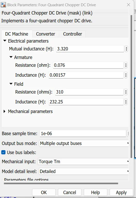
>. And after we assigen the battery parameters after this one is connected to the Dc7 Chopper as shown in abobe model.Battary parameters.
>> From the Output of Dc7 cghhopper select the reuired output for plotting friom the bus selector option,
>> for creating the erro signal /feed reference signal using the gain block from the output speed.
After all the resuklts will be plotting by using the Scope block.
Output results:-
Motor parametersplot :-
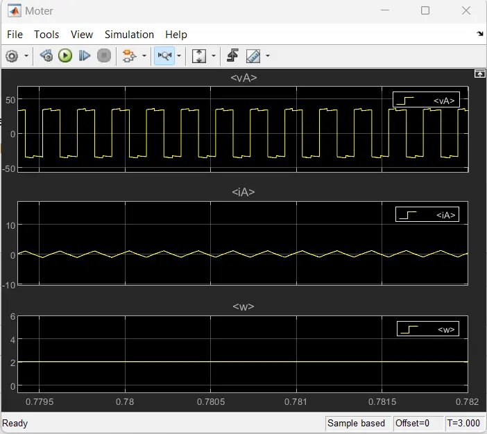
>> from this above Plot we can observe that the
Voltage through Armature
current throught the armatre varation also very timy amount in it.
armature v w will be very low value this can be observe that in above graph .
Controller parameters:-
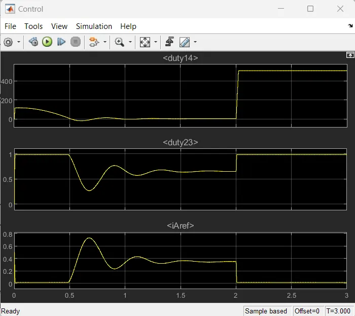
>. from this graph
wecan get the working an and off timing of switching igbts of CHopeers from the top and middle plots.
>>Armature reference current will be observed the accelaration and deselaration positions on it.this will observed from the bottom plot.
Battery parameters:-
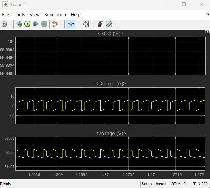
>> from this Graph
we can get the Details regarding the Battery
state of charge (SCo) % and Battery voltge and battary cuurents values as well as.
Top plot for :- battery Soc%
middle plot for :- current of battery
Bottom plot for :- voltage regarding the battery levels.
Conclusion :-The simulink model is created for reuires towing vehicle.
__________________________________________________________________________________________
7)B. Also, Design the parameters in excel sheet.
The design parameters are created in Excell sheet and will be provided link of Excell sheet.
Excel sheet link :- Design_parameters_Machine.xlsx
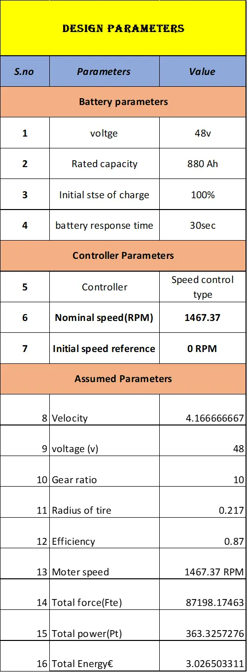
Conclusion :- Therequired Excel sheet is created and provided above.
_________________________________________________________________________________________
Result:-
All Objectives are done in proper way with reqired attamencts are in body part as we as provided link file also.
_________________________________________________________________________________________________________________________________________________________________________________________________________________________(The End)____________________________________________