Week-11 Challenge: Braking
1)For a defined driving cycle, calculate the energy required for braking.
Aim) The main aim is tocalculate the energy required for braking for a defined driving vehicle.
Breaking Energy :-
A moving vehicle possesses kinetic energy and to stop the vehicle, the energy of the moving vehicle has to be converted into another form.
When we accelerate the vehicle, energy in the battery flows to the electric machine to drive itthe energy required for moving the EV vhicle is taken from the bBattery of vehicle.
The actuator pedal is released to slow down the vehicle and when it is completely released, the power flow to the motor from the battery stops. As a result, the vehicle starts to decelerate due to the aerodynamic drag, rolling friction,and other forces that oppose the movement of the vehicle.
But,those friction forces are not sufficient to stop the vehicle and hydraulic brakes are also applied.So, the kinetic energy is converted to heat energy at the brake, and the vehicle stops.
Power electronics converters with bidirectional power flow help out here to store the electric energy generated during braking in an electric vehicle.
How the Energy is reqired for vehicle acceleration likewiseSome energy is also required for vehicle braking also.
The energy Required for breking formula is given as below:-
Energy= 1/2 m (vf-v1)²
where
m= Mass of vehicle (Kg)
vf=final velaocity (m/sec)
Vi=Initial Velocity(m/sec)
Driving cycle:-
I was created the driving cycle (velocity(M/sec with time (sec) by using Excel formet, and this formet is attached below for your reference.
Driving cycle :-
Link :-Ch11_driving_cycle.xlsx


The driving Cycle plot image :-
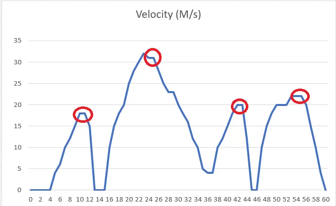
In the above shown plot the points which are highlighted in red circle are the points in which the brakes are applied.
so i will calculate the Braking energy at that points only because those are the points for which the vehicle is decelearting.
Braking energy for this driving cycle with four cases:-
Case 1) starting veleocty(Vs)= 0m/sec and final velocity (vf)=18 m/s
Case 2) starting veleocty(Vs)= 32m/sec and final velocity (vf)=5m/s
Case 3) starting veleocty(Vs)= 19m/sec and final velocity (vf)=0m/s
Case 4) starting veleocty(Vs)= 24m/sec and final velocity (vf)=0 m/s
These all foure cases Breakjing energy is calculated by excel formet and given below link
Link :- Breaking energy.xlsx

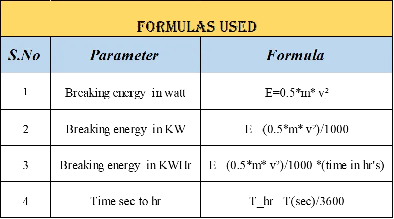
Formulas used for this caluculation :-
Link :- Breakingenergy formmulas.xlsx
Conclusion :-
Breaking enery (Kwhr ):-
Case 1) starting veleocty(Vs)= 0m/sec and final velocity (vf)=18 m/s------>5.4 Kwhr
Case 2) starting veleocty(Vs)= 32m/sec and final velocity (vf)=5m/s------>9.1125 Kwhr
Case 3) starting veleocty(Vs)= 19m/sec and final velocity (vf)=0m/s----->3.08 Kwhr
Case 4) starting veleocty(Vs)= 24m/sec and final velocity (vf)=0 m/s----->4 Kwhr
_________________________________________________________________________________2)Why electric motor can’t develop braking torque at high speed similar to starting? How electric and mechanical brakes are coordinated?
Aim)
(a) The main aim is explanantion why the electric motor can’t develop braking torque at high speed similar to starting
(b)explanantion regarding cordinated nature between electric and mechanical brakes
Answer (a)
An electric motor is an electrical machine that converts electrical energy into mechanical energy. Most electric motors operate through the interaction between the motor's magnetic field and electric current in a wire winding to generate force in the form of torque applied on the motor's shaft.
Electric motors can be powered by direct current (DC) sources, such as from batteries, or rectifiers, or by alternating current (AC) sources, such as a power grid, inverters or electrical generators.
An electrical generator is mechanically identical to an electric motor, but operates with a reversed flow of power, converting mechanical energy into electrical energy.
The speed-torque characteristics of motor:-
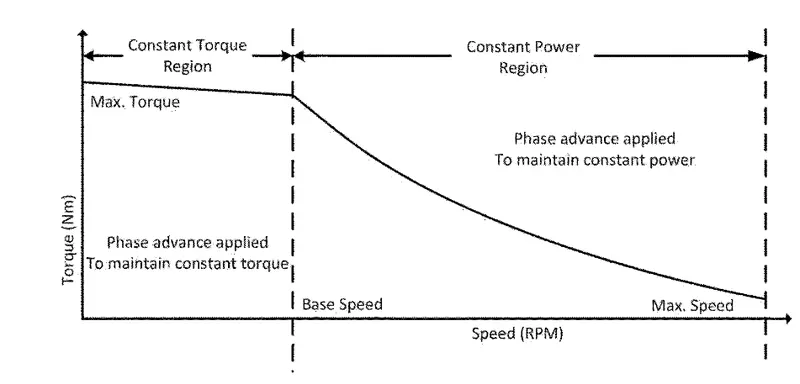
Here it cleared that in the torque-speed curve that till we reach the critical or base speed it has constant torque and once it reaches the critical speed the curve has a downslope which is the constant power region which shows the accelerating operation of the motor. For the decelerating operation motor, this graph is mirrored down which will be having a positive speed and negative torque
Let us consider for Explanantion :-
we can say that EV can achieve 0-100 in 10 sec. Acceleration operation goes this way, with low speed and high torque constant torque region is achieved which has accelerating power and by reaching the critical speed it shifts to constant power region and thus it is for EV to reach 0-100 kmph
As we said the braking operation is mirror images of the above plot so we can not say that the motor producing some positive torque for acceleration can also produce some negative torque for braking. Because we operate in the field of weakening region and operating and above the base speed.
Thus peak acceleration torque will be greater than peak deceleration torque. Thus for acceleration, it has a high torque with the low speed and for deceleration, it has low torque high speed
Conclusion :- From these Points we can conclude that Electric motor can’t develop braking torque at high speed
Answer (b)
Mechanical and electric braking system coordination :
The power converters used are bi directional converter they are bi directional because they need to use the regenerative braking to charge the battery and if the power converter used is of complex type or it is less effective at high speed than it will affect the regenerative braking and hence the brake torque will aslo be affected.
So if we want the braking to be effective it is necessary that we use a mechanical brake with electric brake.
There are two types of braking used in vehicles:
1) Mechanical brake
2) Electrical brake
Mechanical brake :-
Fig -> Mechanical Break image
Mechanical brakes are assemblies consisting of mechanical elements for the slowing or stopping of shafts in equipment drives. They use levers or linkages to transmit force from one point to another. Braking slows or stops the movement of the coupled shafts. mechanical brake acts by generating frictional forces as two surfaces rub against each other.
The stopping power or capacity of brake depends largely on the surface area of frictional surface. They are mainly of two types (Drum brake and Disc brake). These are rough and uncomfortable and they cause wear to braking components. In mechanical braking the whole energy is lost in the form of heat we cannot reuse it.
Electrical brake :-
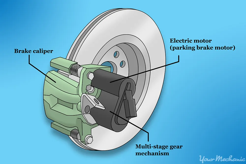
Fig-> Elctrical brake image
Electrical brake is a brake in which the braking is controlled by a electric current. Electric brakes are devices that use an electrical current or magnetic actuating force to slow or stop the motion of a rotating component. They are used in industrial and vehicular braking applications that require fast response times and precise tension control.
They are of several types such as (permament brakes, electromagnetic brakes, eddy current brakes, regenerative brake).In electric vehicles regenrative braking is widely used to charge the battery that is providing current to the motor. These are smooth and comfortable and they do not cause any wear and here we can use that the energy that is lost in the form of heat to recharge the battery.
For low speed vehicle the electrical brake is itself capable of providing effective braking but fot high speed vehicles it is required to use mechanical brake along with electrical brake.
The electrical and mechanical brake are co-ordinated in two types in electric and hybrid electric vehicles and they are:
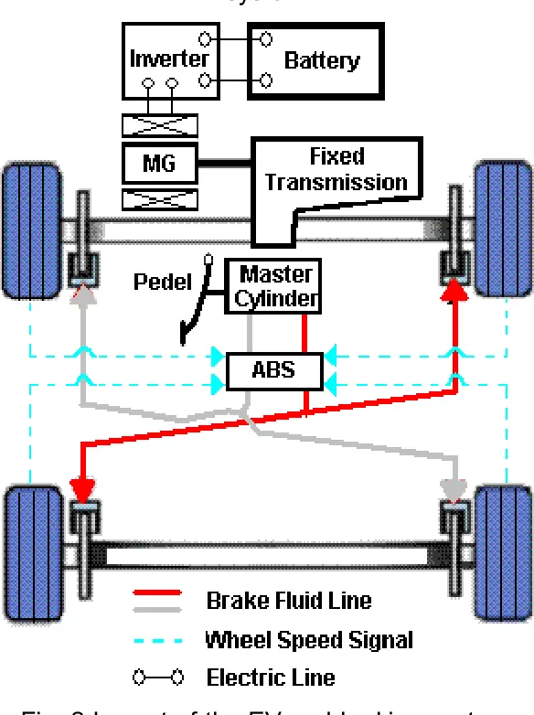
Ev breaking system
The both mechanical and electrical breaking system is cordinated by following two types:-
1) series braking
2) parallel braking
series braking:-
In series braking the brakes are applied one after the other meaning first the electric brakes are applied followed by mechanical brake.
suppose if we are driving a vehicle and we are approaching a traffic signal so before reaching the signal if we release the accelerator paddle than the vehicle's speed will be reduced and regenerative braking will occur and when we reach the signal press the brake paddle which will apply mechanical brake.
so in this way series braking can be done one after the other.
Parallel braking:-
In parallel braking both the electric and mechanical brake are applied at the same time.
When the brake paddle is pressed the brake fluid will reach the brake piston and cause will retard the motion of wheels, there will be some kinetic energy lost.
That kinetic energy lost will be reused at the same time by regenerative braking to charge the power using bi directional motor/generator so in this way both electric and motor brake will work simultaneously.
Conclusion :- Based on These two conditions The Mechanical and electrical breaking are co-oridanted in EV system.
_________________________________________________________________________________________
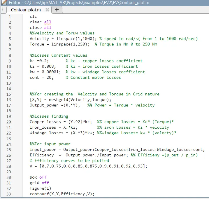
3)Make a MATLAB program which plots contour of given motor speed, torque and efficiency values. Attach the code as a .m file attach a screenshot of all the plots.
Aim) The main aim is creating MATLAb code for plots contour of given motor speed, torque and efficiency values.
MATLAB Program :-
%% MATLAB_CODE_COUNTOUR PLOTS OF SPEED TORQUE AND EFFICIENCY VALUES

clc
clear all
close all
%%velocity and Toruw values
Velocity = linspace(1,1000); % speed in rad/s( from 1 to 1000 rad/sec)
Torque = linspace(1,250);  % Torque in Nm 0 to 250 Nm

%%Losses Constant values
kc =0.2;       % kc - copper losses coefficient
ki = 0.008;    % ki – iron losses coefficient
kw = 0.00001;  % kw – windage losses coefficient
conL = 20;     % Constant motor losses


%%for creating the  Velocity and Torque in Grid nature
[X,Y] = meshgrid(Velocity,Torque);
Output_power =(X.*Y);   %% Power = Tarque * velocity

%%losses finding
Copper_losses = (Y.^2)*kc;  %% copper losses = Kc* (Torque)²
Iron_losses = X.*ki;        %% iron Losses = Ki * velocity
Windage_losses = (X.^3)*kw; %%windgae Losses= kw * (velocty)³

%%For input power
Input_power = Output_power+Copper_losses+Iron_losses+Windage_losses+conL;
Efficiency  =  Output_power./Input_power; %% Efficieny =(p_out / p_in)
% Efficiency curves to be plotted
V = [0.7,0.75,0.8,0.85,0.875,0.9,0.91,0.92,0.93];

box off
grid off
figure(1)
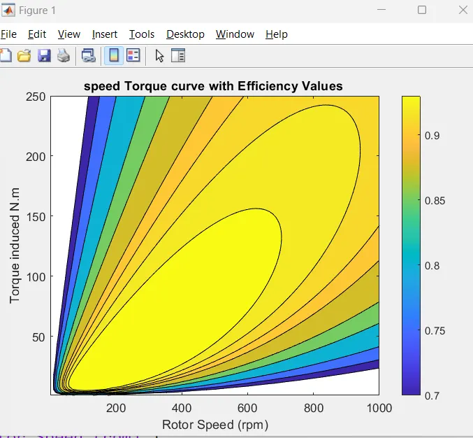
contourf(X,Y,Efficiency,V);
xlabel('Rotor Speed (rpm)')
ylabel('Torque induced N.m')
zlabel('Efficiency')
title('speed Torque curve with Efficiency Values')

figure(2)
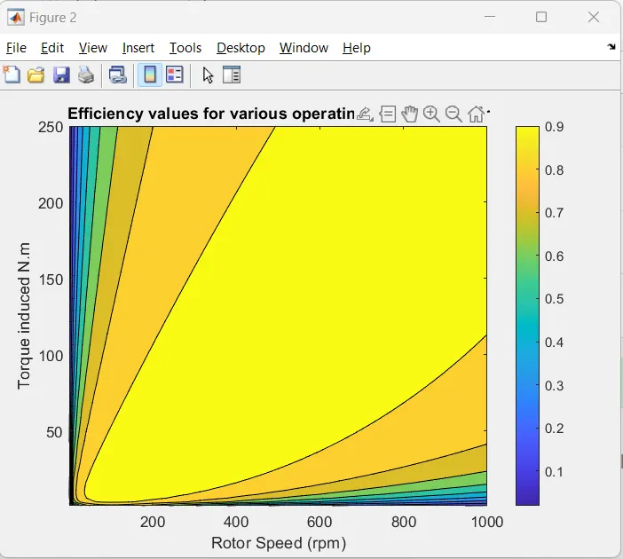
contourf(X,Y,Efficiency)
colorbar
xlabel('Rotor Speed (rpm)')
ylabel('Torque induced N.m')
zlabel('Efficiency')
title('Efficiency values for various operating points of motor')
MAtlab code attamench :-
Output Plots :-
Case 1) starting veleocty(Vs)= 0m/sec and final velocity (vf)=18 m/s------>5.4 Kwhr
Case 2) starting veleocty(Vs)= 32m/sec and final velocity (vf)=5m/s------>9.1125 Kwhr
Case 3) starting veleocty(Vs)= 19m/sec and final velocity (vf)=0m/s----->3.08 Kwhr
Case 4) starting veleocty(Vs)= 24m/sec and final velocity (vf)=0 m/s----->4 Kwhr
2) Electric motor can’t develop braking torque at high speed this nature is explained and also cordination nature betweeb electrical and mechanical breaking also explained.
3) The MATLAB progrom for countor plot of of motor speed, torque and efficiency values is Created and attached MATLAB code with Resultnt plots.