FCEV_Challenge_7
Question-1:-
Load the vehicle parameters. Complete the vehicle model by modelling the remaining equations. Set simulation stop time to 598 sec. The output should be the vehicle velocity.
Aim) The main aim is to load vechicle parameters and to complete the vechicle model by modelling the remaining equations,to set simulation stop time to 598 sec.
ANSWER:-
In this simulink, we have need to develop a model vechicle which is used to find out all the tractive force acting on the vechicle and the power required to overcome this all the resistive force acting on it and propel the vechicle as per the reference speed given.
Vehicle model here is nothing but the equation of forces which comes under velocity ie. when vehicle moves from its rest position for motorized vehicles such as automobiles aircraft and watercraft, vehicle dynamics is the study of vehicle motion.
Fig:- Forces Acting on vehicle Image
The Major forces acting vehicle are as follows:-
a) Rolling Resistance Force
b) Aerodynamic Drag Force
c) Grading Resistance Force
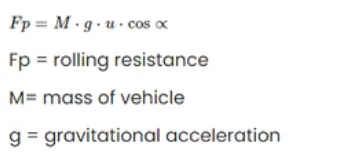
a) Rolling Resistance Force:-
Rolling resistance is the force resisting the motion when a body rolls on a surface.
It can be determined by using the following equatation :-
b) Aerodynamic Drag Force:-
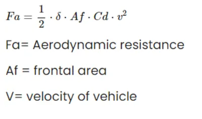
The aerodynamic drag is directly proportional speed of the vechicle.Along the speed of the vechicle the aerodynamic drag also depends on the frontal area or the frontal shape of the vechicle.The vechicle when moving forward,leaves behind on the area of loe pressure.
It can be determined by using the following equatation :-
c) Grading Resistance Force:-
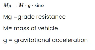
When the car is going up hill it experience an additional resistance componant which is due to the grade of the road and is called the grade resistance but when going downhill,it helps in the motion of the vechicle.
Simulink model :-
For creating the required Simulink Model We have to use the Following Blocks:-
- Switch
- Drive Cycle
- Signal builder
- product
- gain
- constant
- subtract
- Integrator
- goto
- from
- in1
- Out1
- Saturation
- Derivative
- memory
- atan
- intrepreted MATLAb function
- Data looger
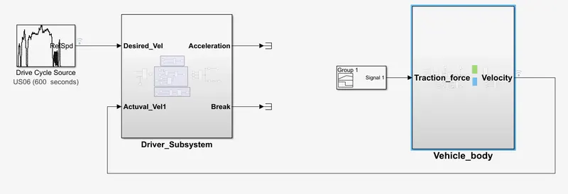
Total Simulink model :-
PROCEDURE:-
The required vehicle model is consists mainly following subsystems
1)Driver Subsystem.
2)Vehicle Body Subsystem.
1)Driver Subsystem:-
The driver Subsystem will be modeling as follows.
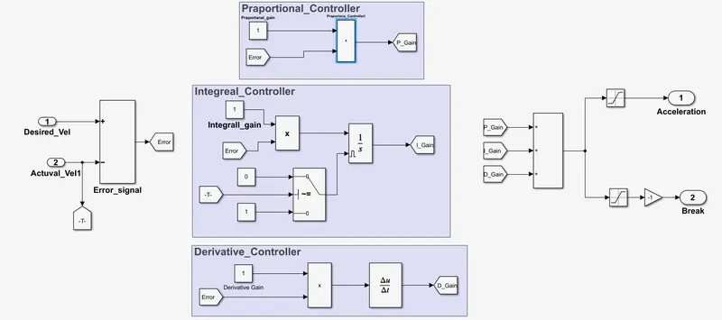
>>The driver Subsystem basically prepared by using the PID controller logic.
>>In this Model the inputs are (a) Desigred velocity
(b) Actual velocity
>>Outputs for the Driver Model is (a) Acceleration
(b) Break command
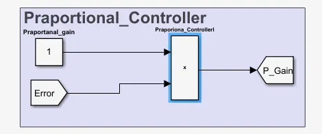
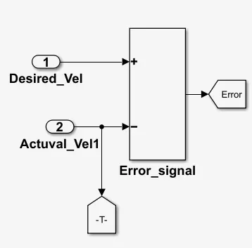
>>In this driver Model firsly we have to design the Praportional controller by using Constant as praportional Gain and error signal as (Difference between Desired velocity and ACtuaval velocity) these two are send to inputs to the input to the Product blcok then we get the output as Praportional controller.
Error Signal modeling :-
After creating the praportional Controller next we have to model the Integral controller as follows.
>>The product of(Integgral gain and Error signal output will be Integrated with respect to the Time by using the "Integrator Blcok".
>>For creating the Integral gain we have to we have to use following Subsytem
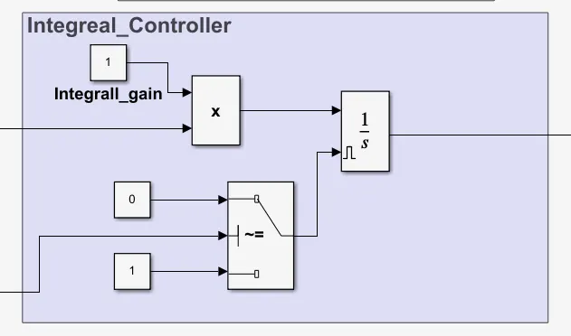
Integral windup rectification purpose we have to the reset as level type in integral blcok.
After creating the Integral controller we have to create the Derivative controller.
Derivative controll will be created by using the following block.
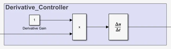
Now total will added by using the Add block
from this PID controller output we have to create the acceleration and break command by usiin the saturation blocks.
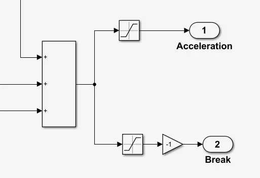
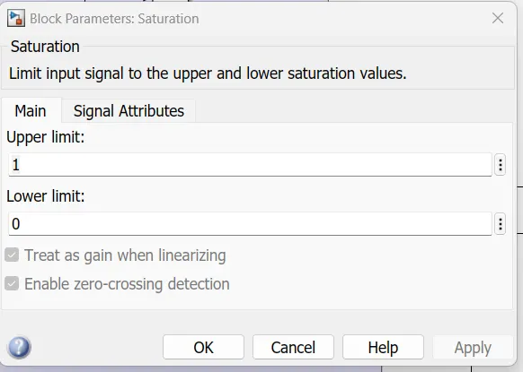
Acceleration Saturation block consisis following parameters values.
Break Saturation block consisis following parameters values.
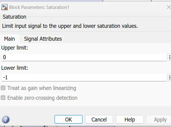
There is no negative velocity in this model that why we are usimng the negative gain block for getting the Positive velocity as Output.
2)Vehicle Body Subsystem:-
This body is created by using the following Subsystem blocks.
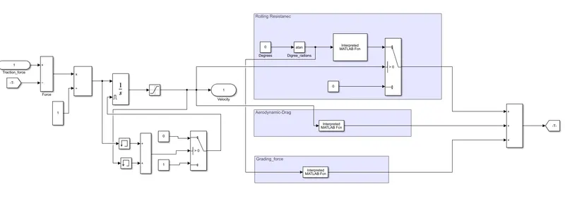
The input of this vehicle body substem is acceleration will getting from the formula below.
We know that,
The formula for Force is
Force = Mass * Acceleration
then,
Acceleration = Force / Mass
but here the force uis subtracted from the actual force to tota traction force.
The total traction force is
Ft= Frr + Fa+Fg
where,
Ft = total force
Fa= Aerodynamic force
Fg= grade force
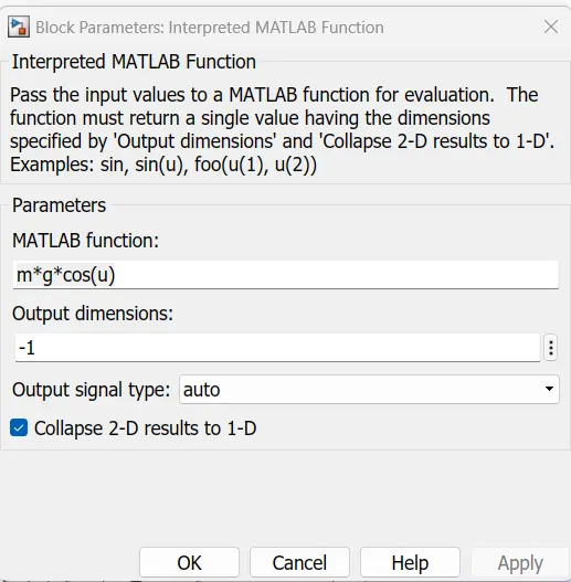
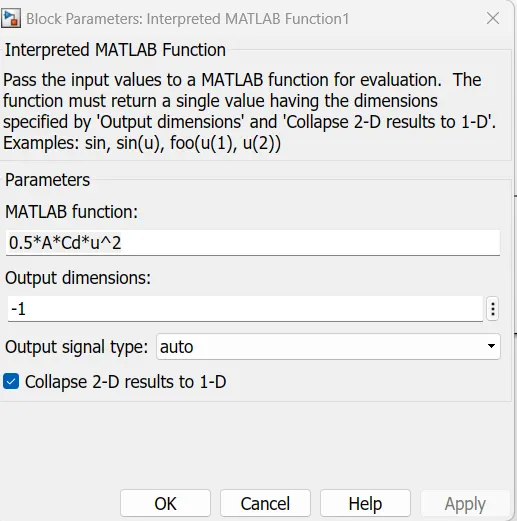
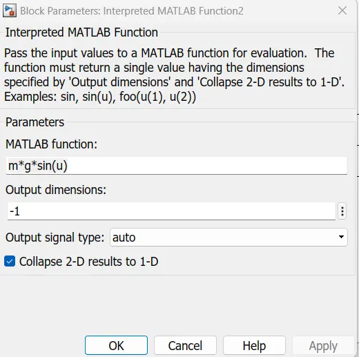
This toatl forces are implemented by using the MAtlab unction using the mathematical formulas which are mention above .
Rolling resistance Fuction :-
Aerodynamic drag force :-
Grading force :-
The values are defined in MATLAb command window as followe.
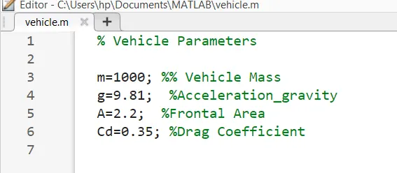
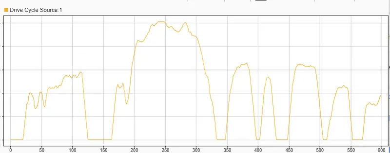
After run the simulation we get the graphical representation for Drive cycel and vehicle velocity as followees.
Note :-the Simulation time is for 598 sec only.
Drive cycle velocity:-
VEhicle velocity graph :-(ZOOMED for understanding purpose)
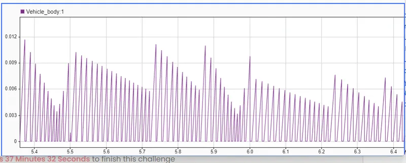
>>Here we can see that how the vehicle is operated by using the drive cycle source
>>we created a vehicle model to obtaine the above results
>>Here the vehicle speed can be varied by chaning the acceleration of the driver block.
Thus the Velocity has been plotted for the time peroid T=598Sec.
---------------------------------------------------------------------------------------------------------------------------------------------
CONCLUSION:- ALL REQUIREMENTS ARE MET
-------------------------------------------------------------------------------------------------------------------------------------
(THE END)