Project 1
1)
1A)
- To select the right corridor for Kochi Metro, different possible options were tried.The three main options tried were
- Alwaye to Vytilla
- Kalamassery to Thripunithura
- Alwaye to Thripunithura
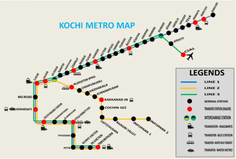
- Based on the expected ridership of the corridor, Alwaye to Thripunithura was selected.
- For this corridor, two-extensions were also tried, one to Kakkanad and the other to Thevra. Impact of these two extensions is marginal on the ridership, hence these extensions are not considered and the corridor from Alwaye to Thripunithura is selected as the best option.
- After carrying out detailed engineering feasibility study for this corridor, it was found that construction of Petta to Thripunithura section of this corridor is not feasible till improvement to existing road infrastructure between these two places is done by the concerned authorities.
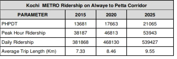
- Accordingly, ridership on the truncated corridor from Alwaye to Petta was worked out which is marginally less from ridership of Alwaye to Thripunithura Corridor.
1B)
ROB’s AT PULLEPADY AND NEAR KSRTC BUS STAND
- Two Road-Over-Bridges (ROBs) across the railway track between Ernakulam town and Ernakulam junction railway stations – one at Pullepady level crossing and the other near KSRTC bus stand connecting Mullassery Canal Road and Salim Rajan Road on either sides of the railway track have been planned by GCDA.
- Completion of these two ROBs will substantially relieve the present traffic congestion on MG Road and Baneji Road as well as on Salim Rajan Road by diversion of traffic towards Kaloor, Pallarivattom, Kakkanad, Thammanam, Vytilla, etc.
- Since construction of Kochi Metro structures on the median of Banerji Road and MG Road will hamper the movement of road vehicles during the execution period, the State Government and the GCDA authorities have been apprised the necessity for early completion of the above two ROBs.
PROPOSED FLYOVER AT EDAPALLY
- At present Edapally junction is a staggered intersection where Alwaye – Ernakulam route is intersected by NH 47 – bypass and NH17 within a distance of 70m and hence it causes a lot of traffic confusion.
- There is a proposal by the National Highway Department to rectify the staggering to make a four-legged intersection. There is another proposal by GCDA to construct a four-lane flyover on the Alwaye-Ernakulam Road.
- In case the proposal of National Highway Department to rectify the staggering to make 4-legged intersection is taken up, it will not affect the Metro alignment. If later, the flyover proposal by GCDA on Alwaye – Ernakulam Road at this junction is also taken up, the Metro alignment will go alongside it. This way Metro and flyover will not obstruct each other. If slight revision of Metro alignment is required, this can be done without any problem.
FLYOVER FROM PALARIVATTOM JUNCTION AT NH 47 BYE - PASS TO HIGH COURT JUNCTION
- The proposal aims to relieve traffic congestion on the major city road which has the highest volume of traffic by creating a flyover or a grade separator to take through traffic.
- The flyover will be 4582m long and is to be designed to carry 2 lanes and hence its width is kept as 8.5m supported on a central pillars. Width of existing road at this location is not adequate to accommodate the proposed flyover along with Kochi Metro.
- Besides, with the construction of Kochi Metro which will relieve substantial amount of traffic moving on the existing road, the need for flyover may not be necessary. It is, therefore, suggested that the State Government may give up the proposal of fly-over at this location.
PROPOSED FLYOVER AT VYTILLA
- GCDA has a proposal for constructing flyover at Vytilla Junction across NH 47 bye-pass, whose alignment will be the same as that of Kochi Metro at this location.
- Road width at this location is not adequate to accommodate proposed flyover as well as Kochi Metro. It is, therefore, suggested that the Metro should be constructed along the Median of road, while GCDA should change its proposal of flyover to that of an underpass below the NH 47 bye-pass.
- Changing the fly- over to under-pass will be much more cost effective for the State Government, than to allow construction of flyover as well as Kochi Metro with double elevation at this location. It is, therefore, strongly recommended hat GCDA should revise the above proposal and plan construction of the underpass along with theconstruction of Kochi Metro. Kochi Metro will be designed to cater for the underpass.
1C)
Location of Depo
It is proposed to establish a depot- cum- workshop at Muttom. The Depot planning is based on following assumptions:
- Enough space is available at Muttom for establishment of a Depot- Cum- workshop.
- All inspection, workshop lines and stabling lines are designed to accommodate two train-sets of 3- car each.
- All stabling lines are planned in the proposed depot-cum-workshop assuming adequate space availability.
- In case of space constraints, if any, stabling facilities may need to be created at terminal stations or elsewhere to cater to the required stability facilities.
1D)
There is no requirement of tunnel route. The entire route is elevated. Maximum of the route is through the center of the road.
1E) Alwaye-Petta Corridor
- Route Length (between dead ends) 612 km
- Number of Stations 23
- Estimated completion cost 3733 crores
Station details
|
S No |
Nam e of Station |
Chainage (in km) N – North S – South |
Distance from Previous Station (in km) |
Height of Rail Level in mtr. From road level |
Platform Type and Nos |
Alignment Description |
|
1 |
Alwaye |
-0.090 |
12.5 |
Side Platform,2 |
On 1000 m curve |
|
|
2 |
Pulinchodu (future) |
1.814 |
1.904 |
12.5 |
Side Platforms, 2 Nos. |
Curved |
|
3 |
Companypady |
2.756 |
0.942 |
12.5 |
Side Platforms, 2 Nos. |
Straight |
|
4 |
Ambattukavu (future) |
3.764 |
1.008 |
12.5 |
Side Platforms, 2 Nos. |
Straight |
|
5 |
Muttom |
4.723 |
0.959 |
12.5 |
Side Platform, 1 No. & Island Platform 1 No. |
Straight Curved |
|
6 |
Apollo Tyre |
6.209 |
1.486 |
12.5 |
Side Platforms, 2 Nos. |
Straight |
|
7 |
Jacobite Church |
7.399 |
1.190 |
12.5 |
Side Platforms, 2 Nos. |
Curved |
|
8 |
Kalamassery |
8.144 |
0.745 |
12.5 |
Side Platforms, 2 Nos. |
Straight |
|
9 |
Pathadi Palam (future) |
9.146 |
1.002 |
12.5 |
Side Platforms, 2 Nos. |
Straight |
|
10 |
Edapally Junction |
10.599 |
1.453 |
12.5 |
Side Platforms, 2 Nos. |
Straight |
|
11 |
Edapally |
12.023 |
1.424 |
12.5 |
Side Platforms, 2 Nos. |
Straight |
|
12 |
Palarivattom |
13.071 |
1.048 |
12.5 |
Side Platforms, 2 Nos. |
Straight |
|
13 |
J L Nehru Stadium |
14.126 |
1.055 |
12.5 |
Side Platforms, 2 Nos. |
Straight |
|
14 |
Kaloor |
15.221 |
1.095 |
12.5 |
Side Platforms, 2 Nos. |
Straight |
|
15 |
Lissi |
15.711 |
0.490 |
12.5 |
Side Platforms, 2 Nos. |
Straight |
|
16 |
Madhav Pharmacy |
16.899 |
1.188 |
12.5 |
Side Platforms, 2 Nos. |
Straight |
|
17 |
Maharaja College |
18.103 |
1.204 |
12.5 |
Side Platforms, 2 Nos. |
Straight |
|
18 |
Ernakulam South Station |
19.332 |
1.229 |
12.5 |
Side Platforms, 2 Nos. |
Straight |
|
19 |
GCDA |
20.185 |
0.853 |
12.5 |
Side Platforms, 2 Nos. |
Straight |
|
20 |
Elamkulam |
21.341 |
1.156 |
12.5 |
Side Platforms, 2 Nos. |
Straight |
|
21 |
Vytilla |
22.447 |
1.106 |
12.5 |
Side Platforms, 2 Nos. |
Straight |
|
22 |
Thaikoodam |
23.703 |
1.256 |
12.5 |
Side Platforms, 2 Nos. |
Straight |
|
23 |
Petta |
24.822 |
1.119 |
12.5 |
Side Platforms, 2 Nos. |
Straight |
2)
2A)
The Contractor shall execute the Works in two phases,
- Design Phase
- Construction Phase.
The Design Phase (Wherever applicable) shall commence upon the date of issue of Letter of Acceptance. This phase shall include the preparation and submission of:
- Preliminary Design
- Definitive Design
- Construction Reference Drawings
The Construction Phase for the whole or a part of the Permanent Works shall commence immediately upon the issue of a Notice by the Engineer/Employer in respect of the relevant Construction Reference Drawings Submission. Such Notice may be issued by the Engineer in respect of a Construction Reference Drawing Submission covering a major and distinctive part of the Permanent Works. However, construction shall not be commenced until the original negatives of the appropriate Working Drawings have been endorsed.
- by the Contractor as "Good for Construction"; and
- by the Engineer that he has no objections to the drawing
The Construction Phase shall include the completion and submission of the Final Design and the preparation and submission of the As Built Drawings and other records as specified.
2B)
- The FIDIC silver book is to be followed.
- The scope of design and construction lies with the contractor.
- Also the project need to be completed within 36 months. Timeline is very important in the project.
2C)
SCC
Sub Contractors
The sub-contracting, excluding design work shall be limited to 50% of the Contract Value. The value of a sub-contract, other than for Design work and Provisional Sums items as and when awarded, should be intimated by the Contractor to the Engineer and it should also be certified that the cumulative value of the sub-contracts awarded so far is within the aforesaid limit of 50%. A copy of the contract between the Contractor and Sub-Contractor shall be given to the Engineer within 15 days of signing and in any case 7 days before the Sub Contractor starts the Work and thereafter the Contractor shall not carry any modification without the consent in writing of the Engineer.
Accurate Setting out
The Contractor shall establish at his cost, at suitable points, additional reference lines and bench marks as may be necessary. The Contractor shall remain responsible for the sufficiency and accuracy of all his bench marks and reference lines. He shall take precautions to see that lines, pints and bench marks fixed by the Engineer are not distributed by his work and shall make good any damage thereto.
Site Data
The Geotechnical and other related data provided by the Employer are based on the investigation conducted by KMRL and are for reference purposes only. The Tenderer should satisfy himself with the data furnished and make his own investigations if required for submitting his offer. Any change in design or construction methodology later during execution on account of change will be borne by the Contractor. If proposed to be carried out by KMRL, will be borne by KMRL.
Employer Supplied Machinery and Materials
No material, tools, plant and equipment shall be supplied by the Employer. The Contractor has to arrange all tools, plant, equipment as well as construction materials required for the work
Design – General Obligations (special requirements)
The Design and Construction Standards shall be in conformity with the requirements of "Rules for Opening of a Railway or a Section of a Railway for Public Carriage of Passengers” and "Rules for Introduction of New Type of Rolling Stock" and to the satisfaction of the Commissioner of Railway Safety whose sanction is mandatory for commissioning of the System.
2D)
Qualification Criteria for Contractor
Eligible Applicant
The tenders for this contract will be considered only from those tenderers {Proprietorship Firms, Partnership Firms, Companies, Corporations, Consortia or Joint Ventures (JV hereinafter)} who meet requisite eligibility criteria prescribed in this document. In the case of a JV or Consortium, all members of the Group shall be jointly and severally liable for the performance of whole contract. Also, each member shall be individually responsible for its duties as specified in the MOU/JV Agreement submitted by the bidder in terms of Clause 1.1(vii)(d).
Performance of each JV/Consortium partner shall also be judged on quarterly basis. In case, the performance of the partner(s) is not found satisfactory, actions as deemed appropriate by the Employer may be taken including termination of contract or termination of any of JV/Consortium member(s) from the contract i.e. part Termination of the contract. In case of part termination of contract, the Performance Security(ies) submitted by the member(s) for their portion of work in contract as per their share in JV/Consortium shall be forfeited and the scope of the work/duties assigned to the defaulting JV/Consortium member(s) as per the MOU/Agreement submitted, may be terminated, however, same may be done by the Employer only if other member(s) of JV/Consortium are ready to complete the entire scope of work. In such a case, remaining works pertaining to the scope of defaulting member of JV, may be completed by other member(s) of JV in the following manner: -
- At their own, if they have adequate technical competence to the satisfaction of employer.
- By subcontracting such scope of work of defaulting member(s) to technically competent Agency with the consent of Employer & without any financial implication to the Employer. In such cases, the limit of subcontracting the works upto 50% of total scope of work shall not apply.
- By induction of new member having adequate technical competence and meeting the original tender eligibility conditions, acceptable to the Employer in JV/Consortium replacing the defaulting member(s) & without any financial implication to the Employer. The new member(s) shall be jointly & severally liable for the performance of the whole contract and also shall submit the Performance Security from their bank account for an amount equivalent to the amount of forfeited amount of Performance security of defaulting member.
In case of i(a) & i(b) above, forfeited amount of Performance Security(ies) of the defaulting member(s) shall be submitted by other member(s) of the JV/Consortium. Further, the performance of each of JV/Consortium member may also be specifically stated in the Work Experience Certificate/Performance Certificates which may be issued to the bidder during or after execution of Work for their Business Development purposes.
In this regard, an undertaking by JV/Consortium members is required to be submitted as per the format Appendix-6A of Form of Tender.
ii(a) A Non-Indian bidder (not restricted as defined in Clause 1.1(xi)) is permitted to tender only in a Joint Venture or Consortium arrangement with Indian Contractor or their wholly owned Indian subsidiary registered in India under the Companies Act-2013. In such JV/Consortium, Indian contractor or Indian subsidiary (owned by foreign bidder) shall have minimum 74% participation and non-Indian bidder shall have maximum 26% participation.
ii(b) A tenderer shall submit only one bid in the same tendering process, either individually as a tenderer or as a partner of a JV. A tenderer who submits or participates in more than one bid will cause all of the proposals in which the tenderer has participated to be disqualified. No tenderer can be a subcontractor while submitting a bid individually or as a partner of a JV/consortium in the same bidding process. A tenderer, if acting in the capacity of subcontractor in any bid, may participate in more than one bid, but only in that capacity.
iii) Tenderers shall not have a conflict of interest. All Tenderers found to have a conflict of interest shall be disqualified. Tenderers shall be considered to have a conflict of interest with one or more parties in this bidding process,
if: - (a) A tenderer has been engaged by the Employer to provide consulting services for the preparation related to procurement or implementation of the project;
(b) A tenderer is any associates/affiliates (inclusive of parent firms) mentioned in sub-paragraph (a) above; or (c) A tenderer lends, or temporarily seconds its personnel to firms or organizations which are engaged in consulting services for the preparation related to procurement for an implementation of the project, if the personnel would be involved in any capacity on the same project. iv) The payment of the tender cost is acceptable from any account. However, tenderer shall submit such transaction details along with their tender submission on GeM portal. If the same transaction reference number has been submitted for more than one bid, all such bids shall be considered ineligible and summarily rejected. v(a) DMRC/ any other Metro Organization (100% owned by Govt.) / Ministry of Housing & Urban Affairs / Order of Ministry of Commerce, applicable for all Ministries must not have banned business with the tenderer (including any member in case of JV/Consortium) as on the date of tender submission. The tenderer should submit undertaking to this effect in Appendix-19 of Form of Tender. v(b) Also no contract of the tenderer of the value more than 10% of the Bid estimated value, executed either individually or in a JV/Consortium, should have been rescinded / terminated by DMRC / any other Metro Organization (100% owned by Govt.) after award during last 03 years (from the last day of the previous month of tender submission) due to non-performance of thetenderer or any of JV/Consortium members. The tenderer should submit undertaking to this effect in Appendix-19 of Form of Tender.
3)
3A)
Scope of Civil Structures
The construction of structures will have to be planned in such a manner that they do not obstruct or interfere with the existing roads/railways and other utilities. Where work is required to be carried out at locations adjacent to such roads/railways, utilities, structures, monuments etc. suitable safety and protection arrangements including sheet pilling wherever required will have to be ensured for which nothing extra will be payable. It should be ensured that no damage is caused to any such element and Engineer/ Employer shall be indemnified against such damage at no extra cost. Sheet piling for retaining the existing road embankment will be paid as per BOQ.
Scope of Architectural Finishing & PHE Works (General)
The work includes entire masonry works within the station buildings along with construction of lintels, mullions and other concrete members embedded in masonry like sunshades, architectural finishes comprising of flooring, finishing, wood works, stone/granite/marble works, stainless/mild steel railing, glass mosaic tiles, aluminium door & windows, steel doors, plumbing, drainage, water supply, sanitary installation & fixtures, glass & Glazing works etc. complete in all aspects and all other works as listed/ specified in drawings & BOQs.
The work under this contract shall consist of, but not limited to all materials, labour, equipments, tools, plants and necessary machinery as required to completely execute all the works relating to Architectural & PHE works and shall be paid on item rate basis under relevant heads of schedule of BOQ.
- All wall treatments including plastering, cladding, tiling and painting.
- Flooring work with Kota stone/marble/granite & ceramic/vitrified tiles etc. as specified at
various locations.
iii. Cavity flooring on pedestal supports as specified.
- Veneering to walls and columns using Kota stone/marble/granite/ceramic tiles/glass mosaic
tiles in columns and walls as specified.
- Aluminum/pre-laminated particle bounded doors with aluminum frames, aluminum windows
with glazing and steel doors with steel frames.
- All fire rated doors & fire rated roller shutters for system rooms and other areas as specified.
vii. Railings, handrails, balustrades in mild steel/stainless steel as specified.
viii. Gates – Rolling shutters and steel gates with architectural elements e.g. fins etc.
- False ceiling works.
- Paints shall be synthetic enamel, distemper, oil bound distemper, plastic /acrylic emulsion
and any other as specified.
- All External architectural works to be done as specified by site architect/Engineer.
xii. All glass works and aluminium works as specified by site architect/engineer.
xiii. Site development works including grading, precise concrete/interlocking tiles, paver blocks,
Kerb stones, bituminous road, water bodies, mounds etc
xiv. Shop drawings for Architectural internal and external finishing shall be developed by the
contractor’s architect and submitted to KMRL for approval prior to commencement of
finishing work at site. The Architect/site engineer shall be engaged by the contractor subject
to the same having relevant experience. All documentation pertaining to the Architect having
the relevant experience shall be submitted to KMRL prior to engagement for approval.
- Public health engineering works like water supply, sanitary and drainage. Plumbing &
sanitary works for toilets and drinking water coolers for staff and handicaps including
provision of water tanks, treatments, boosting and installation of various sanitary fixtures
and appliances as per requirement, soil & waste pipes and disposal of sewage into city main
sewer line or by other alternative method as per BOQ.
3B)
Godrej Interio
Kunal Interiors
NBCC
Ishvakoo(India) Private Limited
3C)& 3D)
3D)
|
CAPITAL COST ESTIMATE |
||||||
|
ALWAYE-PETTA |
||||||
|
Total Length(Dead End to Dead End) : 25.612Km, Ramp = 1.000 Km. UG : 0 Km, Elevated (Including ramp approach depot) = 26.612 Km, Depot At Grade : 1.175 Km |
||||||
|
Total Station =23, |
Elevated : 23 |
|||||
|
S. No. |
Item |
Unit |
Rate as per Price level AUG- 2011 (INR In Crores) |
Qty. |
Amount (INR in Cr.) (Cost Without Taxes & Duties) as per Price level AUG- 2011 |
|
|
1.0 |
Land (INCLUDING R&R COSTS) |
|||||
|
1.6 |
Permament |
LS |
604.00 |
|||
|
Sub Total (1) |
LS |
604.00 |
||||
|
2.0 |
Alignment and Formation |
|||||
|
2.1 |
Elevated viaduct section |
R. km. |
30.142 |
25.612 |
771.98 |
|
|
2.2 |
At Grade |
R. km. |
21.099 |
1.000 |
21.10 |
|
|
Sub Total (2) |
793.08 |
|||||
|
3.0 |
Station Buildings |
|||||
|
3.1 |
Elevated stations ( including finishes) |
|||||
|
a |
Type (A) way side Civil works |
Each |
13.973 |
16.000 |
223.56 |
|
|
b |
Type (A) way side E&Mworks |
Each |
2.254 |
16.000 |
36.06 |
|
|
c |
Type (B) Way side with signaling civil works |
Each |
15.134 |
6.000 |
90.80 |
|
|
d |
Type (B) Way side with signaling E&M works |
Each |
2.438 |
6.000 |
14.63 |
|
|
e |
Type (C), Terminal station |
Each |
17.469 |
1.000 |
17.47 |
|
|
f |
Type (C) Way side with signaling E&M works |
Each |
2.818 |
1.000 |
2.82 |
|
Sub total (3) |
385.34 |
||||
|
4.0 |
Depot |
||||
|
4.1 |
Muttom |
||||
|
a |
Civil works |
LS |
59.93 |
||
|
b |
E&M |
LS |
82.02 |
||
|
Sub total (4) |
141.95 |
||||
|
5.0 |
P Way |
||||
|
5.1 |
Ballastless track for elevated alignment including ramp |
R. km. |
6.738 |
26.612 |
179.31 |
|
5.2 |
Ballastted track at grade |
R. km. |
6.738 |
1.175 |
7.92 |
|
Sub total (5) |
187.23 |
||||
|
6.0 |
Traction & power |
||||
|
Traction & power supply incl. OHE, ASS etc. |
|||||
|
6.1 |
Elevated section |
R. km. |
8.560 |
27.787 |
237.86 |
|
6.2 |
Escalatoe at Elevated Section |
R. km. |
1.001 |
46.000 |
46.02 |
|
Sub total (8) |
283.88 |
||||
|
7.0 |
Signalling and Telecom. |
||||
|
7.1 |
Signalling & Telecom |
R. km. |
12.000 |
26.612 |
319.34 |
|
7.2 |
Automatic fare collection |
Each Stn |
3.079 |
23.000 |
70.82 |
|
Sub Total (7) |
390.16 |
||||
|
8.0 |
R & R incl. Hutments etc. (NO COST AS IT IS INCLUDED IN LAND COST) |
LS |
0.00 |
||
|
Sub Total (10) |
0.00 |
||||
|
9.0 |
Misc. Utilities, other civil works such as median, road signages etc. |
||||
|
9.1 |
Civil works + E&M works |
R. km. |
2.500 |
26.612 |
66.53 |
|
Sub Total (9) |
66.53 |
||||
|
10.0 |
Rolling Stock (SG) |
Each |
8.400 |
66 |
554.40 |
|
Sub Total (10) |
554.40 |
||||
|
11.0 |
CISF BARRACKS ETC. |
LS |
20.00 |
||
|
Sub Total (11) |
20.00 |
||||
|
12.0 |
Total of all items except Land |
2822.7 |
|
13.0 |
General Charges incl. Design charge @7% on all items except land |
197.58 |
|||
|
14.0 |
Total of all items including General charges except land |
3020.15 |
|||
|
15.0 |
Contingencies @ 3 % |
90.60 |
|||
|
16.0 |
Gross Total |
3110.75 |
|||
|
COST WITHOUT LAND |
3111 |
||||
|
Total of cost inclusive of land cost |
3733 |
||||
4A)
4B)
4C)
Project Charter
- SUMMARY
Project Name : Construction of Kochi Metro Phase 1
Project Manager : XYZ
Project Start :2013
Project End : 2017
Total estimated cost (without taxes) : Rs 385 crore
- Goal
Kochi is the city of the state Kerala in India. Today the city does not have any public transport system other than bus services. But this traffic volume is sure to grow multifold in very near future due to its new status as capital city. Due to high land cost and extreme reluctance of the public to part with their lands, widening of roads to accommodate Mass Transit System at road level is almost unthinkable therefore the choice of Mass Transit System for Kochi city must be zeroed down to a Metro System. Metro system is recommended which will serve the needs of the city for all time to come like it will help to improve the transportation and reduces traffic, cost, and pollution issues
- Scope
To construct elevated , at grade metro stations
- Project Objectives
The key goal of this project is to develop a metro in densely populated area of India in order toget following benefits from it.
- Reduce Air Pollution Issues
- Save Travel Time
- Provide a reliable and convenient transit service
- Mitigate the growth of traffic congestion
- Improve mobility for non-drivers
- Parking Cost Savings
- Consumer Savings and Affordability
Key Stakeholders
Mr. X - Project Manager
Mr. Y - Design Head
Mr. Z - Procurement Head
Mr.A - Quality Head
Constraints
Time
Resource
Cost
Sponsor
State Government
Central Government
5
5A)
- L & T
- Systra Group
- Consulting Engineers Group India
- Aarvee Associates
- Egis
5B)
High level scope of design consultants for Station Construction
Construction of the Stations
5.4.6.1 It is proposed to construct the elevated stations with elevated concourse over the road at most of the locations to minimize land acquisition. To keep the rail level low, it is proposed not to take viaduct through the stations. Thus a separate structural configuration is required (although this may necessitate the break in the launching operations at each station locations)
5.4.6.2 Sub-structure for the station portion will also be similar to that of viaduct and will be carried out in the same manner. However, there will be single viaduct column in the station area which will be located on the median and supporting the concourse girders by a cantilever arm so as to eliminate the columns on right of way.
5.4.6.3 Super-structure will consist of 3 pre-cat U Girders for supporting the track structure and I Girder / Double T Girders for supporting the platform and concourse areas. A pre-cast or cast in-situ pre-stressed cross girder will be required over the middle piers for supporting platform structure. Box shaped insitu pre-stressed cantilever cross girders are planned for supporting the concourse girders and escalators at mezzanine level. All the members will be pre-cast in a construction depot and launched at site through cranes.
5.4.7 Grade of Concrete
It is proposed to carry out construction work with design mix concrete through computerised automatic Batching Plants with following grade of concrete for various members as per design requirement/durability considerations.
- i) Pile cap and open foundation - M -30
- ii) Piers - M –40/M-50
iii) All pre-cast element for viaduct and station - M -45
- iv) Cantilever piers and portals - M -45 - M -60
- v) Other miscellaneous structure - M - 30
For all the main structures, permeability test on concrete sample is recommended to ensure impermeable concrete.
5.4.8 Reinforcement and pre-stressed Steel
It is proposed to use HYSD 415 or TMT steel as reinforcement bars. For pre-stressing work, low relaxation high tensile steel strands with the configuration 12 T 13 and or 19 K 15 is recommended (confirming to IS:14268).
5.4.9 Road width required during Construction
As most of the construction is to be carried out on the middle of the road, central two lanes including median will be required for construction activities. During piling and open foundation work, a width of about 8m will be required for construction and the same will be barricaded. It is proposed that two lanes are provided for traffic on either sides during construction by widening of roads, if necessary. In certain cases, one way traffic may be resorted to. All these actions will require a minimum period of about 4 to 6 months. During this period, the State Government can go ahead with the following preliminary works:
- Preliminary action for diversion of utility and preparation of estimates there of
- Reservation of land along the corridor, identification and survey for acquisition.
Once the Corporation is formed, the Corporation has to take action for appointment of consultant for Project Management and proof checking including preparation of tender documents. Simultaneously, action is also to be taken for detailed design for structures for elevated corridors.
5.5 Soil Characteristics & Field Investigation
5.5.1 Field Investigations
- Four boring rigs with all requisite equipments and accessories were mobilised at the work site. A team of technical personnel with skilled labours were also deputed.
- Fifty one boreholes of 150mm diameters were bored to a maximum depth of 45.0 metres below the existing ground level from Alwaye to Thripunithura. The boreholes were made as per IS: 1892-1979.
- Disturbed samples were collected at every change of strata or about 1.5 metres depth interval whichever was earlier. The samples so collected were carefully sealed and numbered with full particulars for identification and sent to the laboratory for conducting the required tests.
- Standard Penetration Tests were conducted in the boreholes at regular intervals of 1.5m as per IS: 2131-1981. In this test, the standard split spoon sampler is driven into the ground at the required depth by means of standard hammer of 63.5 Kgs weight, falling from a height of 75cm. Number of blows for the first 15cm is not taken into consideration because of possible disturbances or presence of settled, suspended matters at the bottom of the bore- holes. The total number of blows for the next 30cm depth of penetration is considered as SPT ‘N’ values 5.5.2 Laboratory Investigation
The following laboratory tests were conducted on the selected samples recovered from the test bore-holes:
(a) Particle size analysis:
(i) Sieve analysis
(ii) Hydrometer analysis
(b) Particle size
(i) Liquid limit
(ii) Plastic limit
(d) Water content
(e) Specific gravity
(f) Direct shear test
(g) Tri-axial test
All the above laboratory tests were carried out as per relevant Indian Standard.
All the samples were identified and classified as per IS: 1498-197
5.5.3 General Geology and Related Characteristics
(a) Location: The Geo technical site investigation carried out from Alwaye to Tripunithura, viaEdapally , Madhav Pharmacy junction, Ernakulam south , Vytilla and Petta.
(b) Physiography and Climate: The city is generally having warm tropical climate with the temperature in summer varying between 240C to 330C and in winter between 220C to 320C. The period between January to April and September to December is generally dry whereas in June, July, October and November it is rainy season. The city has an average annual rainfall of 2540mm.
(c) General Geology: The soils in and around the Cochin City vary from lateritic soils on the Northern part to the Marine clays on the Southern part of the city.From Kochi towards Alwaye, we find the lateritic soils in the op layers changing to granitic rocks in the lower strata. Cochin being a city on the
coast, we have marine clays, loose to stiff in nature for greater depth with dense sand layers underlying these clay layers. There are locations where this sand layer varies occurring from 40 – 60m.
5.5.3.1 Field Investigations
(d) This proposed Kochi Metro Rail is from Alwaye to Petta via Edappally, Madhav Pharmacy, Ernakulam South and Vyttila. A total of 51 bore holes have been drilled at an average distance of 0.5 km each, all along the length of the proposed Metro corridor. Details of Boreholes are given.
5C)
FIDIC Silver book
- Contractor designs and produces, in accordance with the Employer’s Requirements, plant and/or other works and is paid on a lump sum basis (no re-measurement)
- Contractor is liable for errors in Employer’s Requirements
- Administration of contract by Engineer, for Owner(rep)
- Provision for Variations by Engineer(Rep)
- DAB is appointed at beginning of contract
- May be suitable for the provision on a turnkey basis, where:
- Ahigher degree of certainty of firm price and time is required, and
- The Contractor takes total responsibility for the design, procurement and execution of the project, with little involvement of the Employer
- Employer provides Employer’s Requirements, but typically no EngineerSubstantial transfer of risk to the Contractor Where the Owner does not wish to be involved in the day-to-day process of the work Where clear project performance criteria can be specified.
- Where the proponent parties (sponsors, lenders and the owner) are willing to pay more to the contractor and in return the contractor bears the extra risk associated with enhanced certainty of price and time.
- DESIGN ERROR- If errors, omissions, or other defects are found in the Contractor’s Documents, they shall be corrected at the Contractor’s cost, notwithstanding any consent or approval under this Clause.
- EXTENTION OF TIME FOR COMPLETION- The Contractor shall be entitled to an extension of the Time for Completion if delayed by any of the following causes :
- A variation under Sub-Clause 13.3 (Variation Procedure)
- A cause of delay under a Sub-Clause of these Conditions
- Any delay attributable to the Employer
5D)
Design Phase
The Design Phase consists of four sub-phases:
- Programming Phase
- Schematic Design Phase
- Design Development Phase
- Construction Document Phase
Programming Phase
The Programming Phase is concerned with the following:
- Estimating realistic project cost.
- Determining the building and user requirements.
- Establishing a total building area.
- Refining the scope of work.
Programming involves gathering information from the intended building occupants and user groups through group and individual interviews. The programmer researches current and projected needs in such areas as information and instructional technology, academic teaching methods, privacy and security. This results in a comprehensive description of the necessary components of the construction project.
This is the time to determine the effect on existing facilities or projects-in-planning, and the need for corollary projects, such as parking lots or new utilities services. State of Michigan building requirements or restrictions, all life safety, fire, environmental and barrier-free code issues are identified.
The project program, the end result of the Programming Phase, describes how the finished project will "work": how it will function for the building occupants and how it will meet all the project requirements.
Schematic Design Phase
The Schematic Design Phase is concerned with:
- Building systems(structural, mechanical, HVAC, plumbing and electrical).
- Interior and exterior finishes.
- Building site.
The purpose of Schematic Design is to translate the project program into physical drawings of space. In the Schematic Design Phase, the project team determines the areas, physical requirements and relationships of all the required building spaces and components, confirms or revises the total building square footage, the total project budget and the project schedule and occupancy dates.
It provides control strategies for all equipment and systems relating to building services such as security and fire alarms, and defines the technical requirements for phones, data, cable and audio/visual needs.
The schematic drawings—floor plans, site plans and building elevations—are reviewed and refined for functionality, usability, required adjacencies, code compliance, security, safety and aesthetics. The project program and the schematic drawings are scrutinized for possible errors or omissions. The plans are shared and discussed with staff in other areas of the University such as maintenance services, custodial services , logistics, information technology and public safety, to identify possible problems and to coordinate with the needs and practices in these areas.
Design Development Phase
The Design Development Phase is concerned with the following:
- Interior and exterior building materials and finishes.
- Furniture and equipment selection and layouts.
- Cabinetry and custom fabrications.
- Lighting and technology designs.
- Mechanical, electrical and plumbing systems.
In the Design Development Phase, the schematic plans and elevations are reviewed, revised and expanded to incorporate all the details and specifications required for construction. Project components are looked at to the smallest detail. Issues often come to light that affect constructability or are critical to satisfying the project program, and that may require changes to the project program or to the budget, or both.
By the end of design development the design drawings and specifications are sufficiently complete to establish and define the facility's size, function, configuration, spaces, the operation or use of equipment and the materials for all the principal building structures and systems. With this information the project budget, schedule and all building plans are finalized.
Construction Document Phase
The Construction Document Phase is concerned with the following:
- Compliance with all applicable state and federal codes and statutes.
- Compliance with university standards.
- Verification of the building site conditions.
- Quality controls during the Construction Phase.
- Estimates of all associated costs.
Construction documents are compiled from design development documents. They include all the architectural drawings and specifications necessary to complete the project, and are the basis of the bid documents and the construction contract. The estimated project costs are reviewed and updated to reflect current construction costs, and are compared with the established project budget. If it is no longer feasible to complete the project within the established budget, alternative approaches and practical cost reductions are identified.
At the end of the Design Phase, the project is ready to be constructed and the construction budget is ready for your approval. The deliverable of the Design Phase are the design documents, construction documents and the preliminary contract document package. Once the construction budget is approved, the Construction Phase begins.
6))
6A)
PROVISION OF LABOUR CAMP
The Contractor, shall, at his own expense, make adequate arrangements for the housing, supply of drinking water and provision of bathrooms, latrines and urinals, with adequate water supply, for his staff and workmen directly or through sub-contractors employed on the Works at the location authorised by Engineer. No labour camp shall be allowed at work site or any unauthorised place.
The Contractor at his own cost shall maintain all campsites in a clean and sanitary condition. The Contractor shall obey all health and sanitary rules and regulations, and carry out at his cost all health and sanitary measures that may from time to time be prescribed by the Local/Medical Authorities and permit inspection of all health and sanitary arrangements at all times by the Employer, Engineer and the staff of the local municipality or other authorities concerned. Should the Contractor fail to provide adequate health and sanitary arrangements these shall be provided by the Employer and the cost recovered from the Contractor. The Contractor shall at his own cost, provide First Aid and Medical facilities at the Labour Camp and at work sites on the advice of the Medical Authority in relation to the strength of the Contractor’s staff and workmen, employed directly or through sub-contractors. The Contractor shall at his own cost, provide the following minimum requirements for fire precautions:
- Portable Fire Extinguishers.
- Manual Fire Alarms.
- Water Supply for use by the Fire Service.
The Contractor at his own cost shall provide necessary arrangements for keeping the camp area sufficiently lighted to avoid accidents to the workers. He should also ensure that electrical installations are done by Trained Electricians. These installations shall be maintained and daily maintenance records must be made available for inspection of the Engineer.
6B)
It is proposed to establish a depot- cum- workshop at Muttom. The Depot planning is based on following assumptions:
(i) Enough space is available at Muttom for establishment of a Depot- Cum- workshop.
(ii) All inspection, workshop lines and stabling lines are designed to accommodate two trainsets of 3- car each.
(iii) All stabling lines are planned in the proposed depot-cum-workshop assuming adequate space
availability. In case of space constraints, if any, stabling facilities may need to be created at terminal stations or elsewhere to cater to the required stability facilities.
In broad terms, based on the planned Rolling Stock requirements, conceptual design on following aspects and will work as a guide for detailed design later:
- Layout of Stabling-shed, Inspection-shed, minor repairs and heavy repair overhauling
workshop and cleaning of Rolling Stock.
- Operational and functional safety requirements.
- Ancillary buildings for other maintenance facilities.
- Electrical & Mechanical Services, power supply and distribution system.
- Water Supplies, Drainage & Sewerage.
Land of 12.8096 ha. for car maintenance depot at Muttom and construction depots, is proposed to be acquired. The depot is planned at ground level. Costs have been worked out for various items of building, elevated structures, tracks, boundary wall & plants machinery etc.
6C)
Bulk Material - Station Construction
|
Sl.No |
Description |
Unit |
Quantity |
|
1 |
Blocks |
Cum |
7934.44 |
|
2 |
STONE / GRANITE / MARBLE WORKS |
Sqm |
5786.271 |
|
3 |
Cement |
Bags |
|
|
4 |
Steel |
Ton |
6D)
The company requires 100,000 number of hollow blocks every year for all projects together. The cost each block is Rs 8. The Work involved in ordering requires 25 man-days with average man-day cost of Rs 500. The inventory carrying cost is 8%.
|
EOQ - Blocks |
|||
|
SL.No |
Description |
UOM |
Amount |
|
1 |
Total units reqired per year (N) | Nos | 1,00,000.00 |
|
2 |
Cost of each block (C) |
Rs |
8 |
|
3 |
Work involved in ordering |
man days |
25 |
|
4 |
Average manday cost |
Rs |
500 |
|
5 |
Order cost (A) |
Rs |
12500 |
|
6 |
Annul Carrying Cost (I) |
Percentage |
8 |
|
5 |
EOQ |
SQRT(2*N*A/C*I) |
|
|
6 |
Economic Order Quanity |
nos |
62500 |
|
7 |
No of orders per year |
nos |
N/EOQ |
|
nos |
1.60 |
||
|
2 |
|||
|
8 |
Time interval |
Months |
7.50 |
The company orders cement bags every 2 months for the quantity of 3000 numbers. It costs them Rs 1500 against each order. The cost of cement bag is Rs 250 with storage cost per year Rs 30 per bag.
|
EOQ |
|||
|
SL.No |
Description |
UOM |
Amount |
|
1 |
Total units required per year (N) |
Nos |
18,000.00 |
|
2 |
Cost of each bag (C) |
Rs |
250 |
|
3 |
Order cost (A) |
Rs |
1500 |
|
4 |
Annul Carrying Cost (I) |
Percentage |
12 |
|
5 |
EOQ |
SQRT(2*NA/CI) |
|
|
6 |
Economic Order Quanity |
nos |
1341.640786 |
|
7 |
No of orders per year |
nos |
N/EOQ |
|
13.42 |
|||
|
13 |
|||
|
8 |
Time interval |
Months |
0.89 |
6E)
Sub-Contractor
Works as listed below and those dealing with proprietary materials. Products may be carried out
by the contractor through the Sub-Contractors as may be approved by the Engineer in writing.
The Sub-Contractors must be firms of repute and long standing, having adequate experience
and complete facilities to carry out all items of work required for completion as per Specifications
and expected quality to the satisfaction of the Engineer. The Sub-Contractor must also have
personnel experienced in preparing shop drawings. All such works shall be carried out under the
direct supervision of the manufacturers of the proprietary materials / products or their trained and
accredited licensee
- a) Masonry Work
- b) Plastering Work
C)False Ceiling Work
D)Waterproofing
E)Painting
7)
7A)
Earthmoving equipment- Excavator, Backhoe loader, Compactor
Concreting equipment- Batching plant-Dry & Wet, Transit mixers, Concrete pumps
7B)
BUY, RENT and LEASE Options
Before acquiring the equipment, it is essential to explore all the options by considering various parameters namely,
- Company’s cash flow
- Working capital
- Equipment Utilization and its maintenance
- Obsolescence and replacement
- Operating Conditions
- Scope for repetitive usage
Buying
- Buying results in direct ownership of the equipment.
- Acquisition of equipment by buying is done either through cash purchase by using company funds or through financing purchase.
- However cash purchase can have an adverse effect on company’s cash flow as it reduces the liquid asset thus affecting company’s working capital.
- In such cases, financing options are explored
Renting
- It is an alternative to direct ownership (i.e. through buying) of the equipment for a shorter period.
- Acquisition of equipment through renting is suitable when the contractor or the construction company requires the equipment for a project task of shorter duration.
- Rental period may a day, a week or a month and may go up to one year.
- The rental rates are generally established on daily basis, weekly basis or monthly basis.
Leasing
- For a longer period of time as compared to renting
- It is a long term alternative to direct ownership of the equipment.
- The leasing company (i.e. owner of the equipment) is known as lessor whereas the user of the equipment is known as lessee.
- Mostly the lease period is more than six months and may run up to years.
- Most of the equipment leases are non-cancellable.
7C)
Equipment Diesel Requirement-
Excavator - 50l/day
Backhoe loader - 30l/day
Compactor - 30l/day
Front End Loader- 35 L/operating hour
Piling equipment-50L/hr
7D)
|
Sl.no |
Equipment |
Fuel Consuption for 2 years (L) |
Budget for fuel (Rs) |
Budget for buying |
Total Budget |
|
1 |
Excavator - 50l/day |
36000 |
2880000 |
3379930 |
62,59,930.00 |
|
2 |
Backhoe loader - 30l/day |
21600 |
1728000 |
2105980 |
38,33,980.00 |
|
3 |
Compactor - 30l/day |
21600 |
1728000 |
1005980 |
27,33,980.00 |
|
4 |
Front End Loader- 35 L/operating hour |
25200 |
2016000 |
1805980 |
38,21,980.00 |
|
5 |
Piling equipment-50L/hr |
36000 |
2880000 |
1900000 |
47,80,000.00 |
|
2,14,29,870.00 |