Modelling and 2D meshing a car back door, generating property card
Objective:
To import the given model and perform manual mid surfacing and 2D meshing and assign thickness to the model
Quality Criteria:
Target Element size - 5mm
| S.N | Quality Criteria | Value |
| 1 | Aspect Ratio | 5 |
| 2 | Skewness | 45 |
| 3 | Warping | 15 |
| 4 | Taper | 0.5 |
| 5 | Min. Length | 4mm |
| 6 | Max. Length | 7mm |
| 7 | Min angle Quad | 45 |
| 8 | Max angle Quad | 135 |
| 9 | Min angle Tria | 30 |
| 10 | Max angle Tria | 110 |
| 10 | Tria % | 15 |
Procedure
1. Import the given CAD model and change the user interface to radioss and delete existing solids.
2. Since the model was symmetric about Z-axis. Delete half of the surfaces and separate the backdoor component into 3 components i.e. inner surface, the upper surface, and the lower surface.
3. Perform auto mid surface to each component individually.
4. Check for proper mid surfaces. Create manual mid surface using offset command to create the surfaces which are not captured by auto mid-surface command.
Specify the offset value during manual mid surfacing as half of the thickness of the model surface.
5. Defeature for minimum length as 5 mm for surface fillets and edge fillets.
6. Measure the length of the surfaces if they are less than 5 then toggle the edges in order to to get a good mesh.
Perform proper topology clean-up by using toggle, Filler surface, extend the surface, replace points commands.
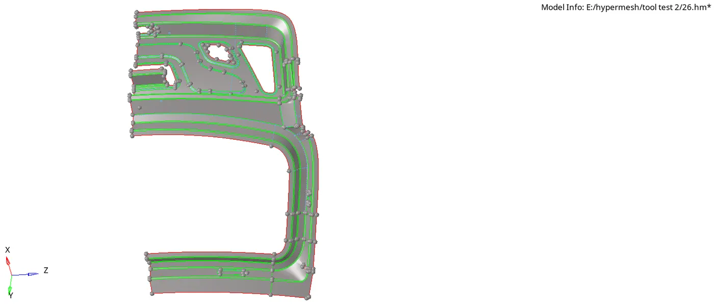
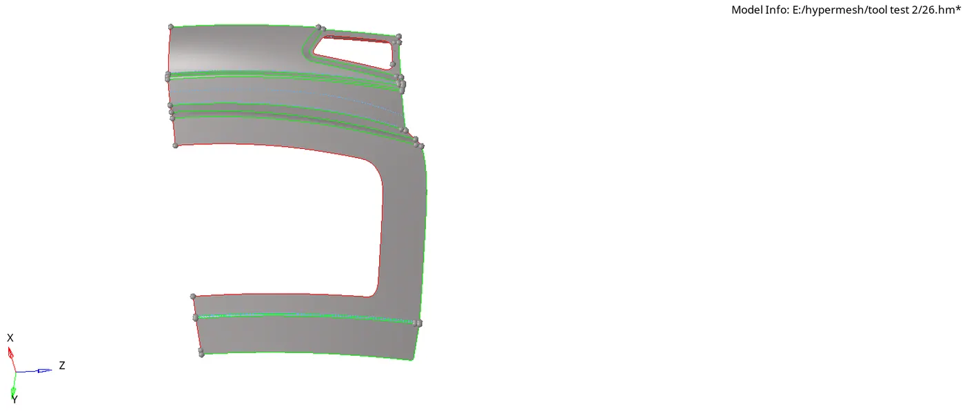
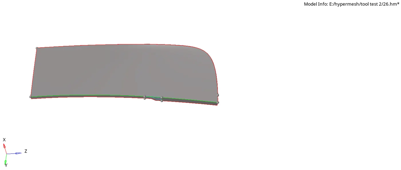
Do this for all three components. Following are the surfaces after topology cleanup
Inner Panel
Upper Body
Lower Body
10. After performing geometry cleanup perform a 2D mesh with quad elements as average element size 5 mm.
11. Keep tweaking the mesh in order to get a good mesh flow and follow all the given quality criteria.
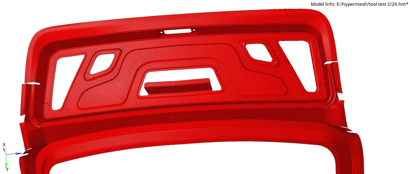
12. After the mesh of the half of symmetric component is complete; reflect the surface as well as the mesh from the tool menu in the menu bar.
Inner Body
Upper Body
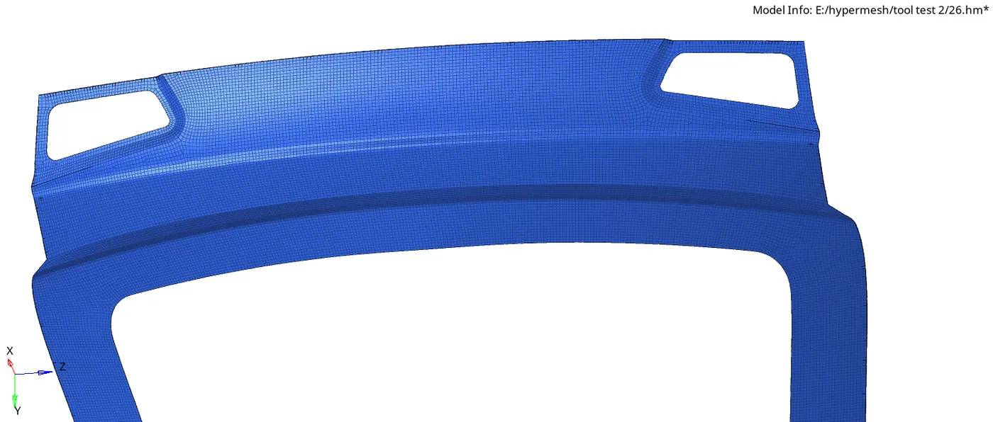
Lower Body
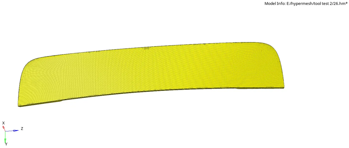
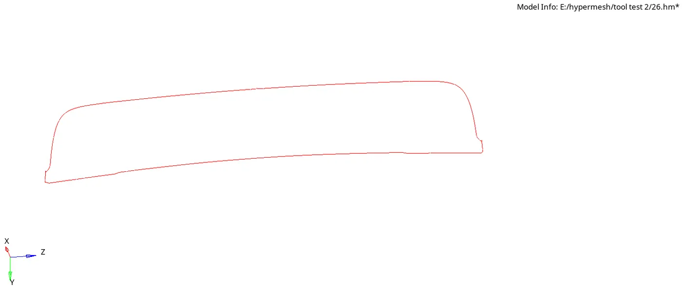
13. Check for free edges if found, equivalent them.
Inner Body
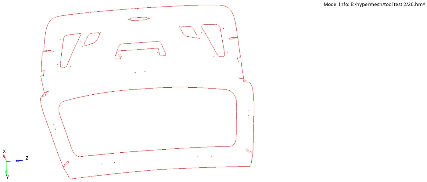
Upper Body
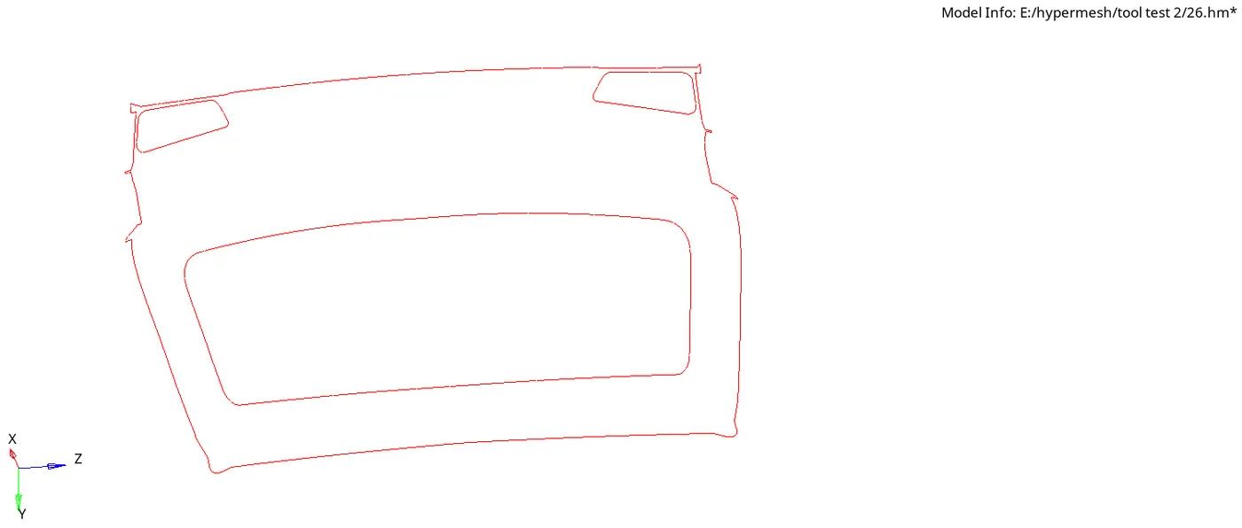
Lower Body
14. Assign thickness in the tool tab area of the component.
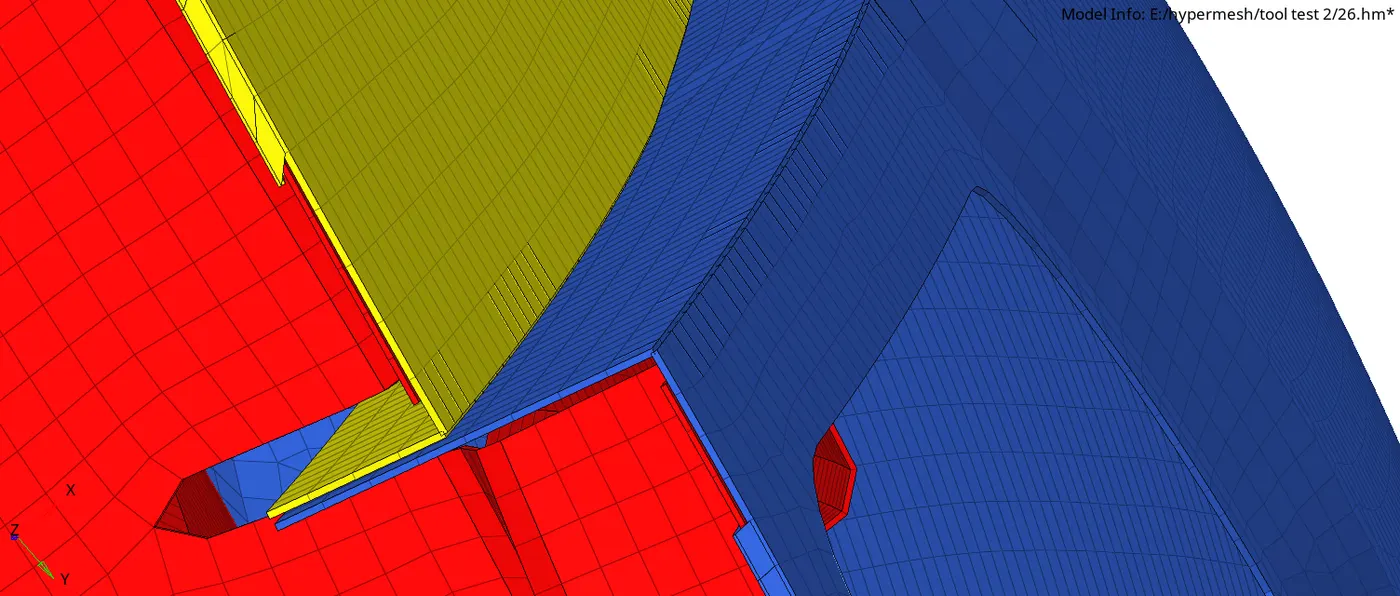
Create two thickness properties by thickness 0.6 and 0.75
A thickness of 0.75 has been assigned to the upper and lower panels.
A thickness of 0.60 has been assigned to the inner panel.
The thickness of all these components is shown below. (Turn to 2Ddetailed element representation to view thickness of elements.)
Conclusion and results:
1. We have learned extracting manual mid surfacing for the geometry where the automatic surface does not capture the surface well
2. performing 2D meshing.
3. Assigning thickness to the model.