MBD Simulation on IC Engine Valve Train
AIM :
To create models, assembly & perform Motion analysis for the IC engine valve train .
OBJECTIVE :
- To obtain the results for Valve Lift.
- Calculate and display the plots for contact force between Cam and Push Rod, Pushrod and Rocker Arm, Rocker Arm and Valve.
INTRODUCTION :
- In IC engines, valve train is a mechanical system that controls operation of the intake and exhaust valves during the working of internal combustion engine.The valve train of an internal combustion engine includes components required to control the flow of gases into and out of the combustion chamber. This includes valves and related components required to allow the air-fuel mixture to enter the combustion chamber, seal the combustion chamber during compression and combustion, and evacuate exhaust gases when combustion is complete.
THEORY :
- The engine valve train consists of all the components responsible for transferring the rotational movement of the camshaft into the opening and closing of the intake and exhaust valves.
- The major components of the valve train are –
Camshaft
The timing and lift profile of the valve opening events are controlled by the camshaft, through use of a carefully shaped lobe on a rotating shaft. The camshaft is driven by the crankshaft and in the case of a four-stroke engine rotates at half the speed of the crankshaft.
Push Rod
Pushrods are long, slender metal rods that are used in overhead valve engines to transfer motion from the camshaft (located in the engine block) to the valves (located in the cylinder head). The bottom end of a pushrod is fitted with a lifter, upon which the camshaft makes contact. The camshaft lobe moves the lifter upwards, which moves the pushrod. The top end of the lifter pushes on the rocker arm, which opens the valve.
Rocker arm
Depending on the design used, the valves are actuated by a rocker arm, finger or bucket tappet. Overhead camshaft engines use fingers or bucket tappets, upon which the cam lobes contact. Overhead valve engines use rocker arms, which are actuated by a pushrod and pivot on a shaft or individual ball studs in order to actuate the valves.
Valves
Most modern engines use poppet valves type, although sleeve valves, slide valves and rotary valves have also been used at times. Poppet valves are typically opened by the camshaft lobe or rocker arm &closed by a coiled spring called a valve spring. Valve float occurs when the valve spring is unable to control the inertia of the valvetrain at high engine speeds (RPM).
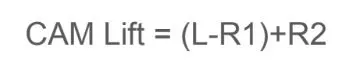
- Formula used for calculation of Cam profile parameters for both the cases 1& 2 is -
PROCEDURE :
- Start with the 2D sketches for all the parts and convert it in to 3D and save all the parts separately as a part file.
- Assemble the parts one by one by using various mates and constraints.
- After assembly apply the material to all the parts.
- Then, start with the motion analysis setup.
- In the motion analysis setup 1st setup the motor with the cam axis of 1500 rpm rotating clockwise.
- Apply the contact sets with all the parts for cam, push rod ,rocker arm and valve respectively.
- Set the motion study properties like frames required per second for analysis.
- Calcuate the results and display the plots for Linear displacement of various parts and also the contact force generated among them.
- Finally, animate and saved the motion study and obtain all the required results.
SETUP :
2D SKETCH :
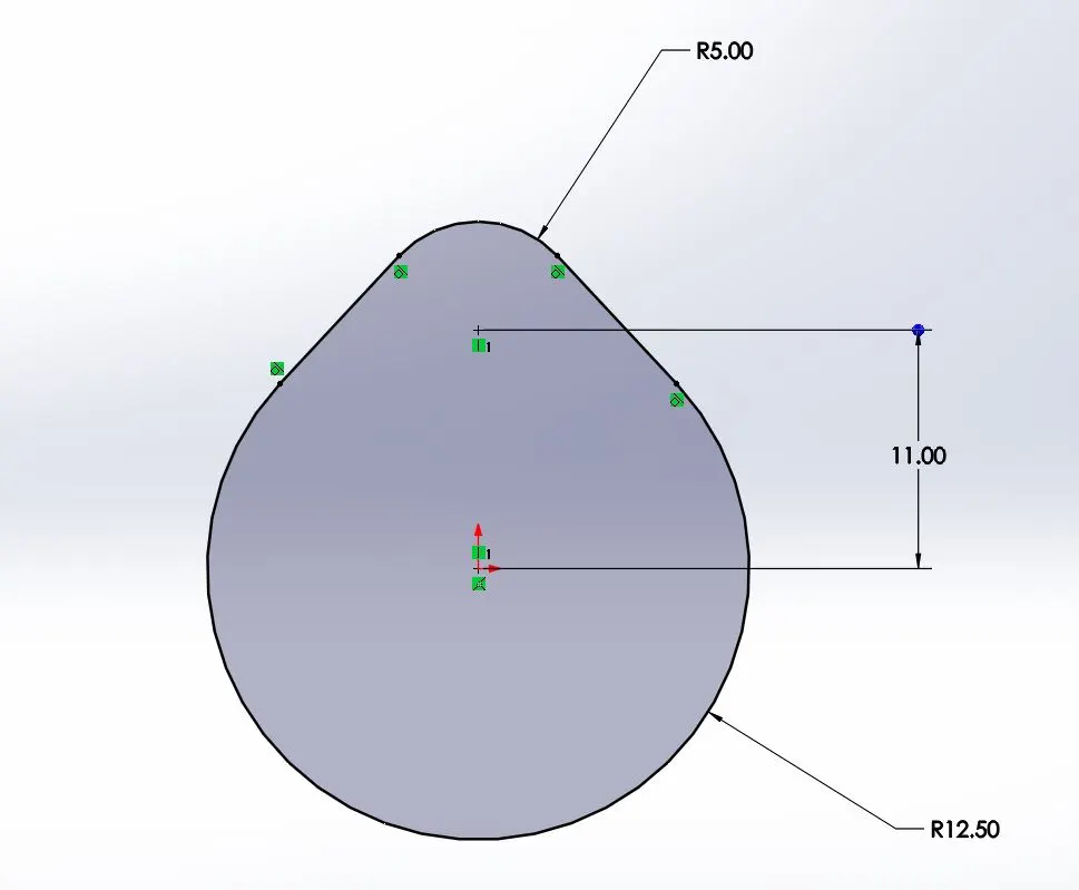
2D sketch for 3.5 mm Valve lift CAM
2D sketch for 6 mm Valve lift CAM
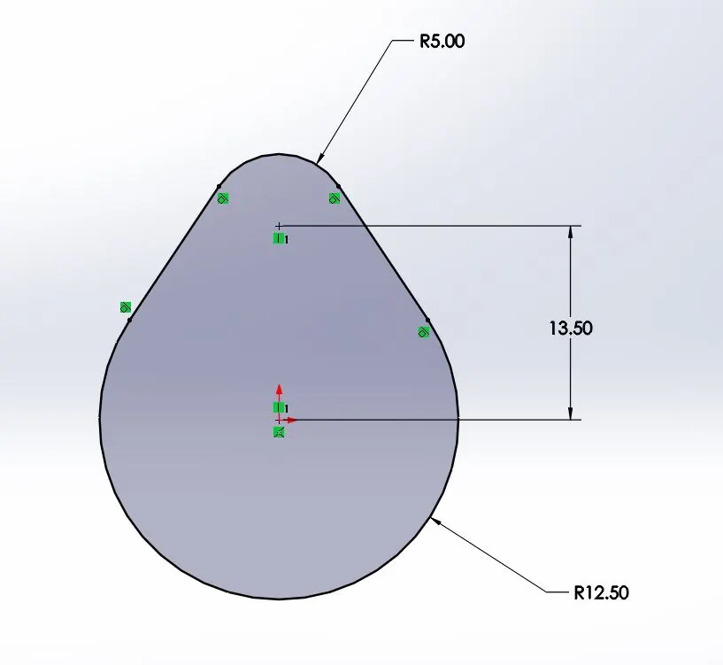
- The above images shows the 2 D sketch for CAM. 1st sketch is for 3.5 mm Cam lift and 2nd is for 6mm Cam lift of various dimensions.
3D MODEL :
Cam
Push rod

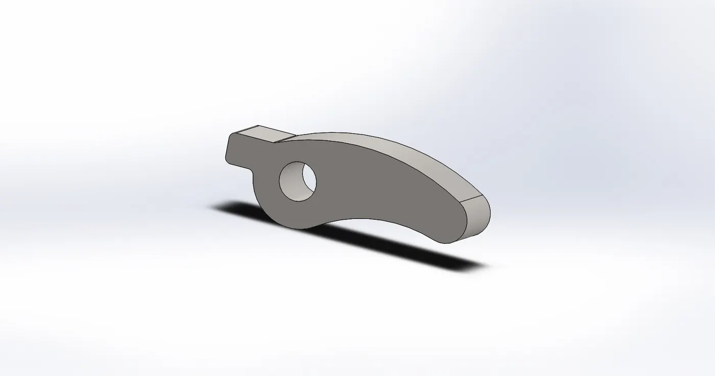
Rocker arm
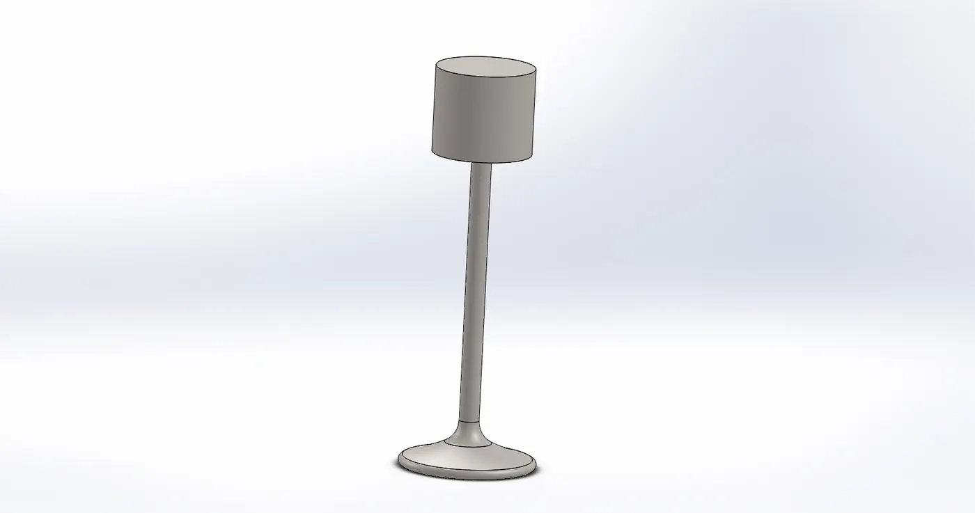
Valve
Valve Mount
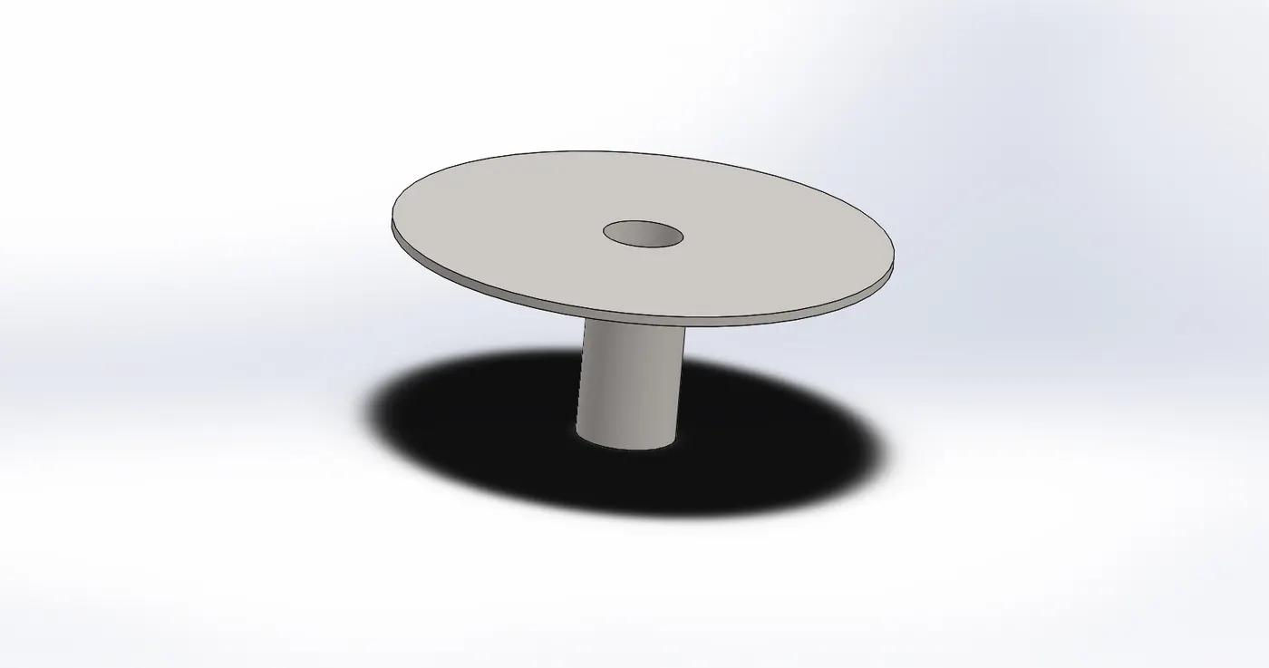
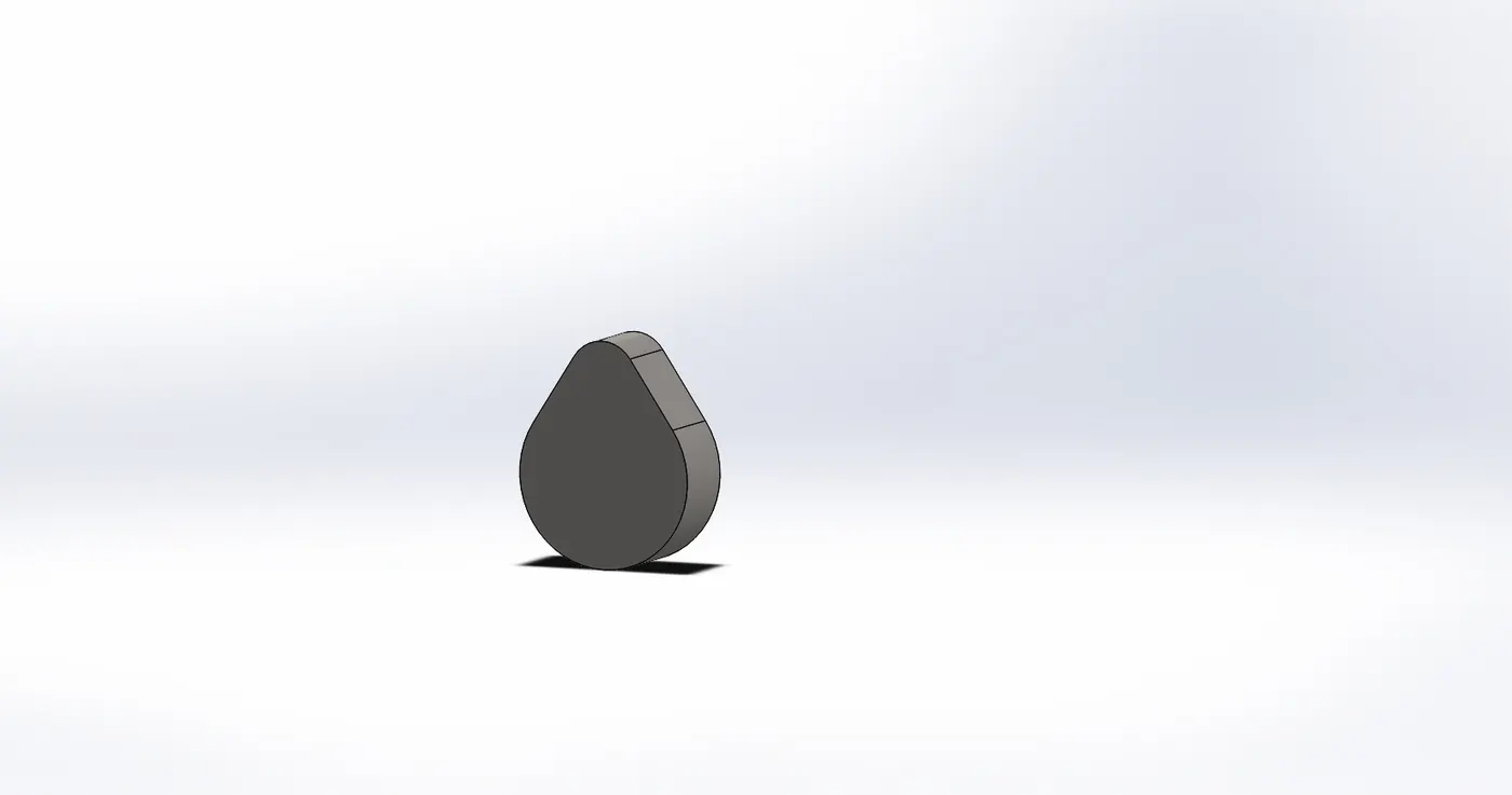
- The above images shows the all 3 D model parts for cam, push rod, rocker arm, valve and valve stem.
ASSEMBLY :
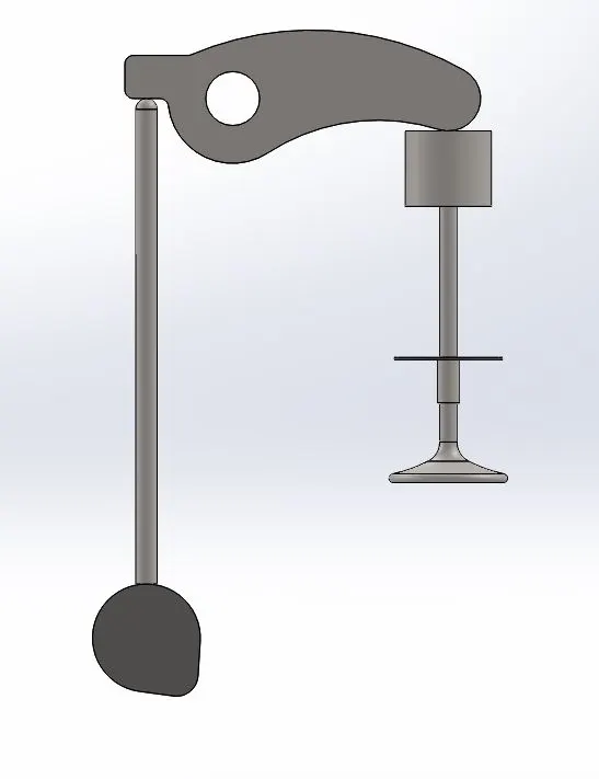
- This assembly is for case 1 i.e. 3.5 mm cam lift .
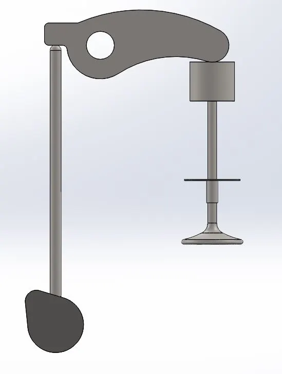
- This assembly is for case 2 i.e. 6 mm cam lift .
MOTION STUDY SETUP :
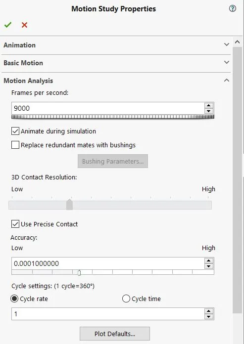
The above setup indicates the properties initialized for motion analysis that is 9000 frames per second (fps) for 1500 rpm.
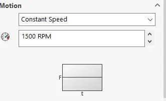
Calculation for fps –
RPM – 1500
Therefore, 1500 * (360/60) = 9000 fps.
Hence, we had set 9000 fps with precise contact for 15000 rpm for both the cases 1 & 2 motion analysis.
RESULTS :
CASE 1 - For 3.5 mm CAM Lift
Linear displacement for valve
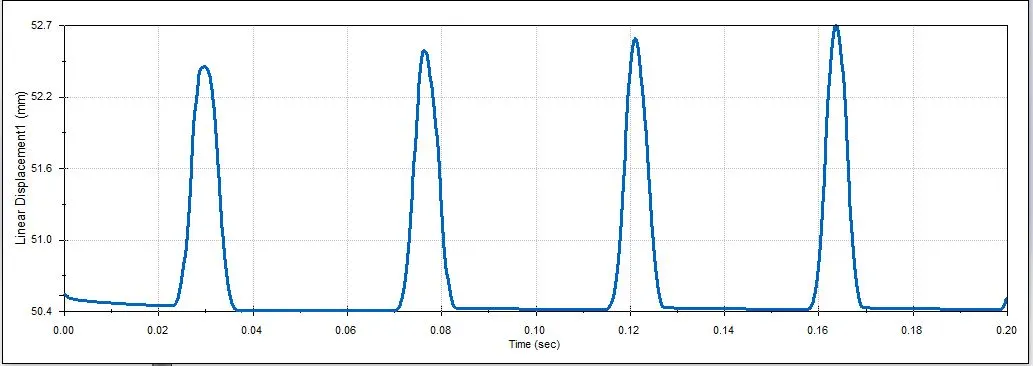
- The above plot shows the linear displacement for valve with respect to time
Linear displacement for push rod
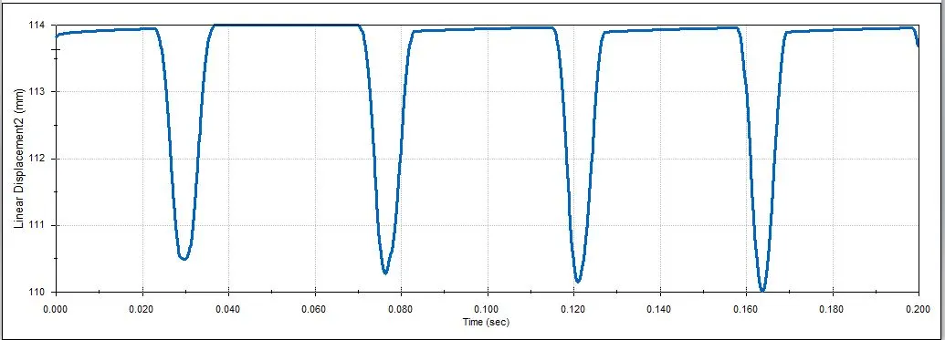
- The above plot shows the linear displacement for push rod with respect to time.
Contact force between Cam & Push Rod
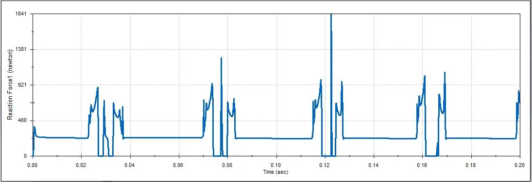
- The above plot shows the contact force between the Cam and Push Rod.
Contact force between Push rod and Rocker Arm
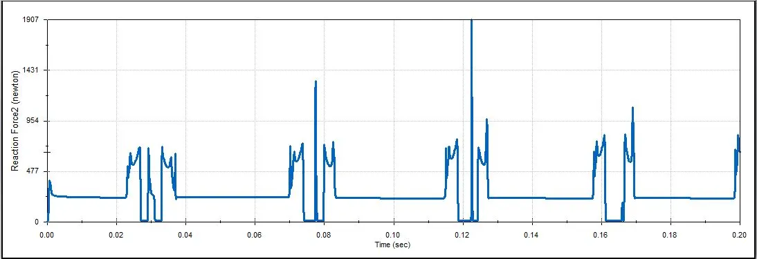
- The above plot shows the contact force between Push rod and Rocker Arm.
Contact force between Rocker Arm and Valve (for Magnitude)
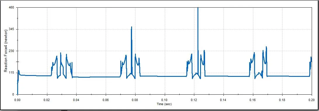
- The above plot shows the contact force between Rocker Arm and Valve for its magnitude.
Contact force between Rocker Arm and Valve (for X direction)
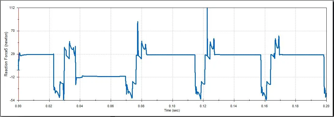
- The above plot shows the contact force between Rocker Arm and Valve along X axis.
CASE 2 - For 6 mm CAM Lift
Linear displacement for valve
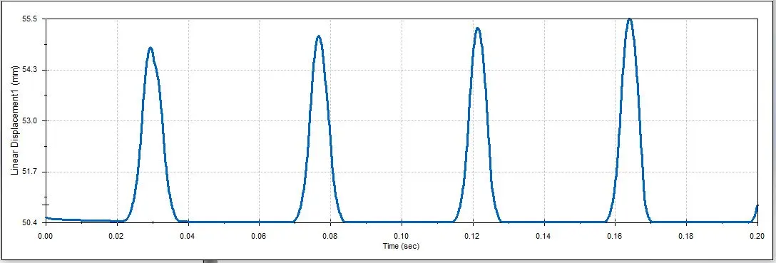
- The above plot shows the linear displacement for valve with respect to time.
Linear displacement for push rod
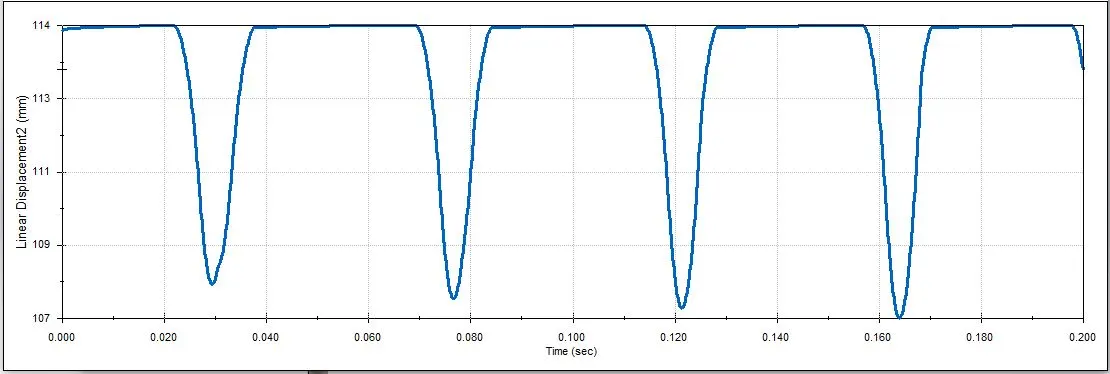
- The above plot shows the linear displacement for push rod with respect to time.
Contact force between Cam & Push Rod
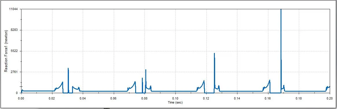
- The above plot shows the contact force between the Cam and Push Rod.
Contact force between Push rod and Rocker Arm
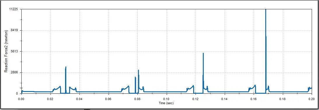
- The above plot shows the contact force between Push rod and Rocker Arm.
Contact force between Rocker Arm and Valve (for Magnitude)
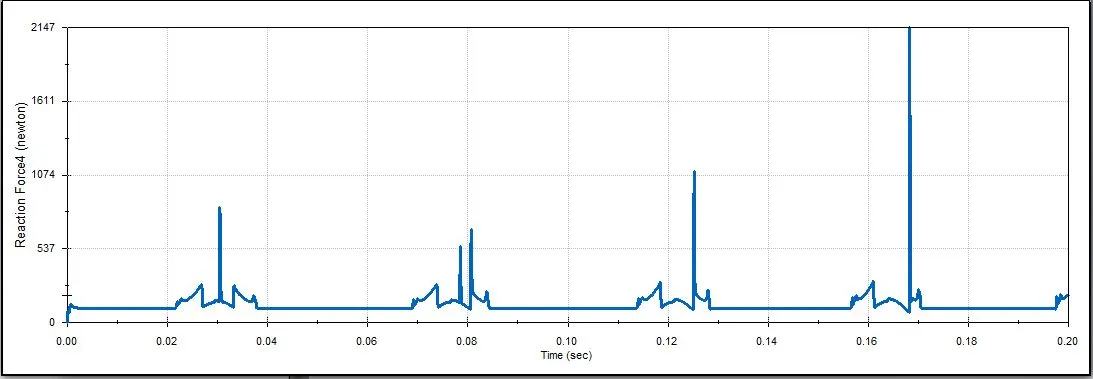
- The above plot shows the contact force between Rocker Arm and Valve for its magnitude.
Contact force between Rocker Arm and Valve (for X direction)
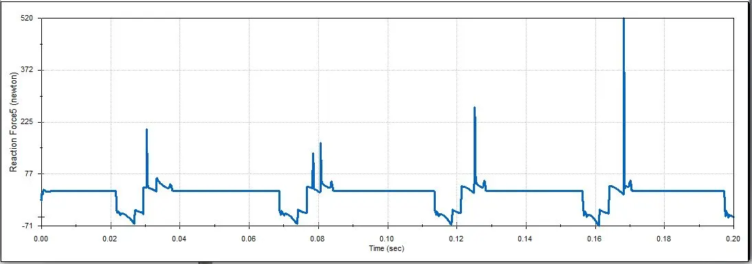
- The above plot shows the contact force between Rocker Arm and Valve along X axis.
OBSERVATION :
- We can observe the various contact forces generated among cam, push rod, rocker arm and valve respectively for cam lift of 3.5 mm for case 1 & 6 mm case 2. The results among the cam lift for 6 mm indicates the maximum force as compared to case 1 because as we increase the cam lift from 3.5 mm to 6 mm the force as well as the displacement increases among the engine valve train parts. The max. contact force between cam and push rod is 11044 N for case 2 i.e. for 6 mm cam lift respectively.
- Contact force between the Rocker arm and valve varies while measuring with respect to the X direction and measuring with respect to magnitude because the rocker arm with respect to x direction has its movement is in both directions backward as well as forward and also in X directional it denotes the frictional force. For rocker arm and valve measuring with magnitude varies because magnitude is the net results for forces of the 2 components thus, contact force varies for measuring with respect to X direction and while measuring magnitude.
CONCLUSION :
Thus, we had understood the Motion analysis of the IC engine valve train and how the forces acts on its various components. Also, studied about the displacement of components of valve train while in motion during its operation. We had successfully plotted and analyzed the results for contact forces and linear displacements of the valve train components.
ANIMATION :
CASE 1 -
Motion analysis of IC Engine Valve train for cam lift around 3.5 mm.
CASE 2 -
Motion analysis of IC Engine Valve train for cam lift around 6 mm.
REFERENCES :