STATIC ANALYSIS FOR A PLATE WITH HOLES
AIM :
To perform the Static Analysis on two different models of a plate with the holes and the comparison of results among the two models.
OBJECTIVE :
- Prepare a static analysis and get the output for stress, strain and displacement for two models of plate with holes.
- Compare the final results of static analysis for the two cases.
INTRODUCTION :
Static Analysis –
- A static structural analysis determines the displacements, stresses, strains, and forces in structures or components caused by loads that do not induce significant inertia and damping effects. Steady loading and response conditions are assumed; that is, the loads and the structure’s response are assumed to vary slowly with respect to time.
Stress concentration –
- This increase in stress due to sudden change of geometric shape is called stress concentration. Similar to the fillet radius, holes, notches, or grooves also bring in sudden change in the geometric form. This means all the features will also be associated with stress concentration effect.
THEORY :
Static Analysis -
The types of loading that can be applied in a static analysis include:
- Externally applied forces and pressures
- Steady-state inertial forces (such as gravity or rotational velocity)
- Imposed (nonzero) displacements
- Temperatures (for thermal strain)
In other words, these features are used more static loading conditions which does not change over the time and location.
Stress concentration –
- The stress concentrators are geometrical irregularities that cause an increase in the average effort that should be present in regions near these discontinuities, the relationship between the maximum stress that occurs and the average effort that should occurs is defined as stress concentration factor.
- The rectangular bar with a central hole, subjected to tensile load, if the bar is cut in the cross section of the hole, the stress distribution along the cut surface is substantially uniform until reaching the vicinity of the hole, where efforts suddenly increase.
For this project there are 2 cases selected for analysis such as-
- Flat Plate with a single hole,
- Plate with three holes.
PROCEDURE :
- Create a 2 D sketch of a plate with a hole on its center and convert it into 3D by using features.
- Select the type of analysis to perform in simulation in our case choose static analysis.
- Apply the material to the part as required.
- Apply the fixture using fixed geometry to a smaller face of the plate to grip it.
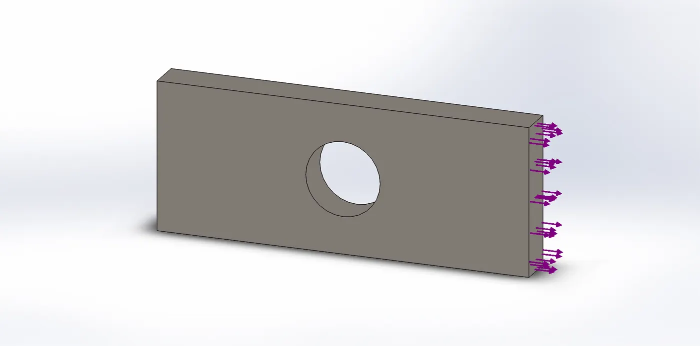
- Apply the external load on the face of the plate to analyze the force effects.
- Create a Mesh on the Part model before proceeding further.
- Run the simulation and display the results for stress, strain and displacement for particular cases.
- Compare the obtained results with each case.
CASE SETUP :
PART MODELLING :
CASE 1
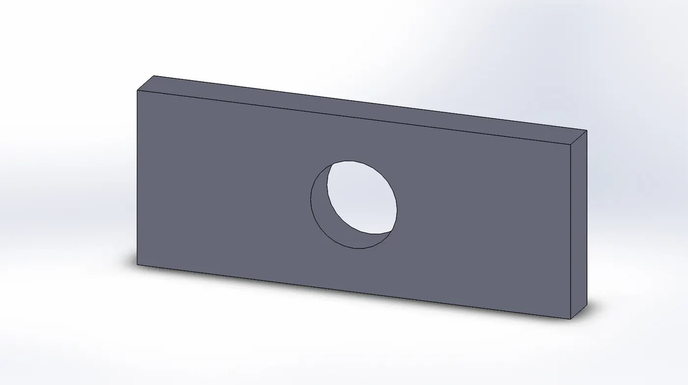
- Start with the 2D sketch by making a rectangle of length 300 mm and height 120 mm with a 60 mm diameter circle as a hole in the center of the rectangle.
- Next, convert the 2D sketch into 3D by giving thickness around 30 mm for plate by using extrude tool from features.
CASE 2
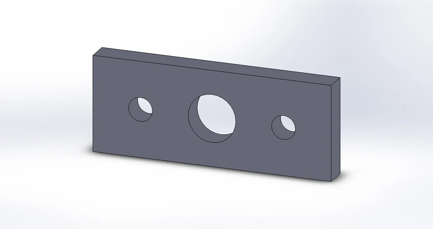
- Create a 2D sketch by making a rectangle of length 300 mm and height 120 mm with a 60 mm diameter circle as a hole in the center of the rectangle. Sketch the 2 holes by using circles on both the sides of center circle on the plate.
- Next, convert the 2D sketch into 3D by giving thickness around 30 mm for plate by using extrude tool from features.
MATERIAL :
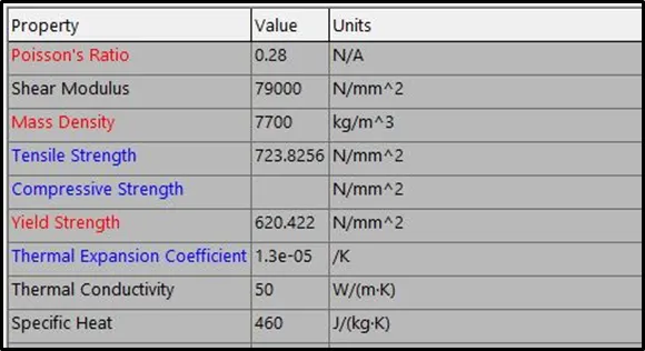
- The material selected is alloy steel which had yield strength of 640.22 N/mm^2. To apply material, simply select the part then choose apply material option for a 3D part, choose a material as required then apply and close the tab.
FIXTURE :
CASE 1
CASE 2
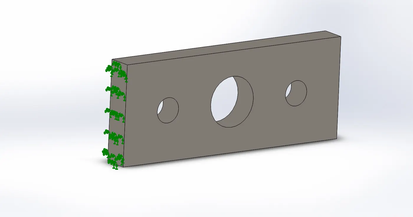
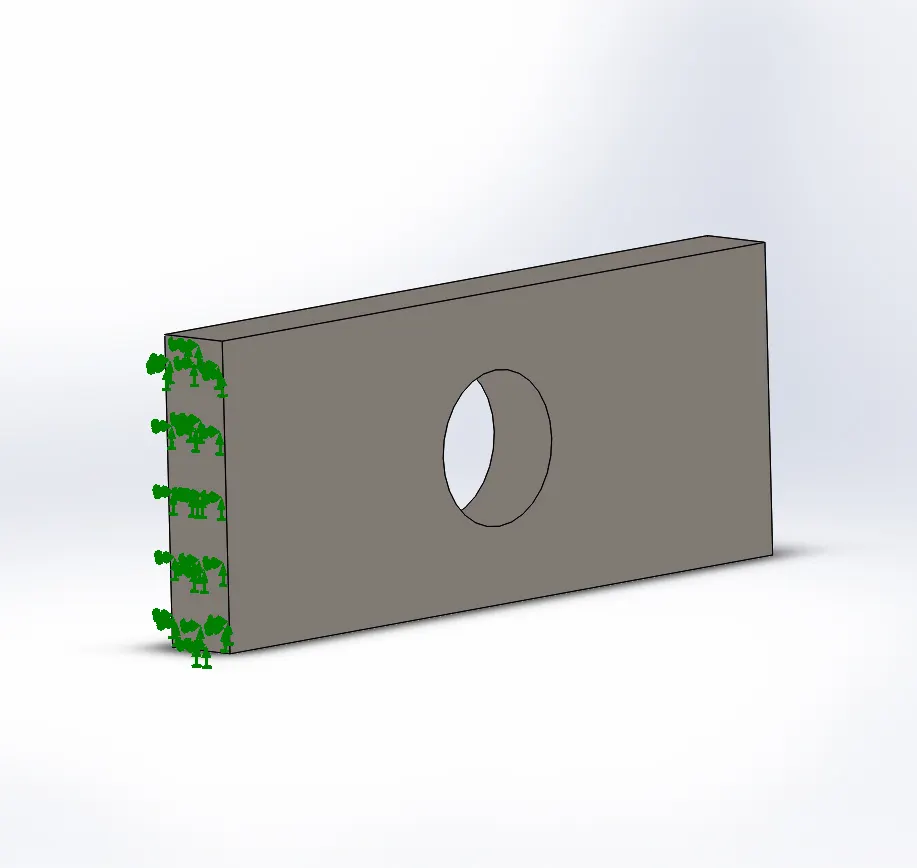
- Apply a fixture on the rectangular plate using fixed geometry. Here, the plate is fixed from one side that is from left side on the face and free from the other side to apply loading.
LOAD :
CASE 1
CASE 2
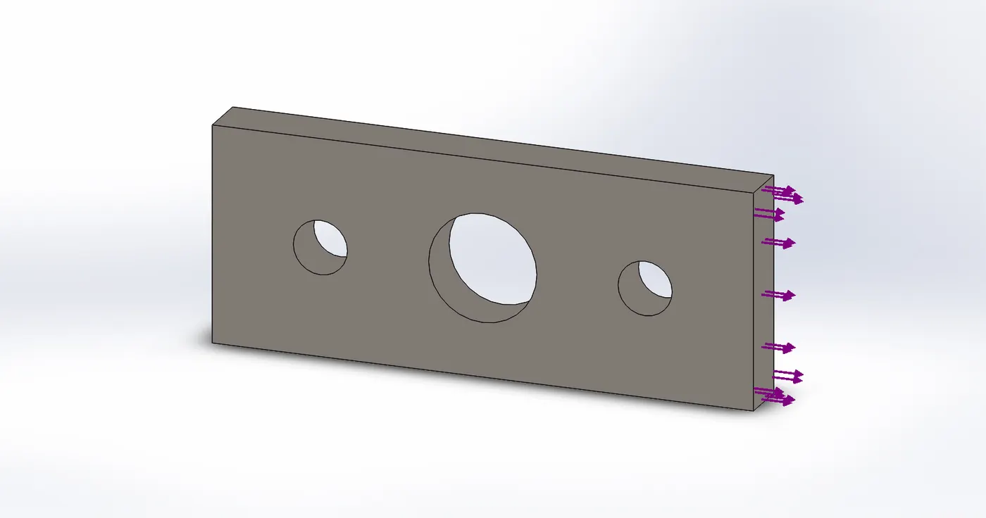
- Load is generally applied on the edge or face of the part as per the required analysis and part to be simulated. A force of 1000 KN is applied on the right side face of the plate to analyze its effects over the plate.
MESH :
CASE 1
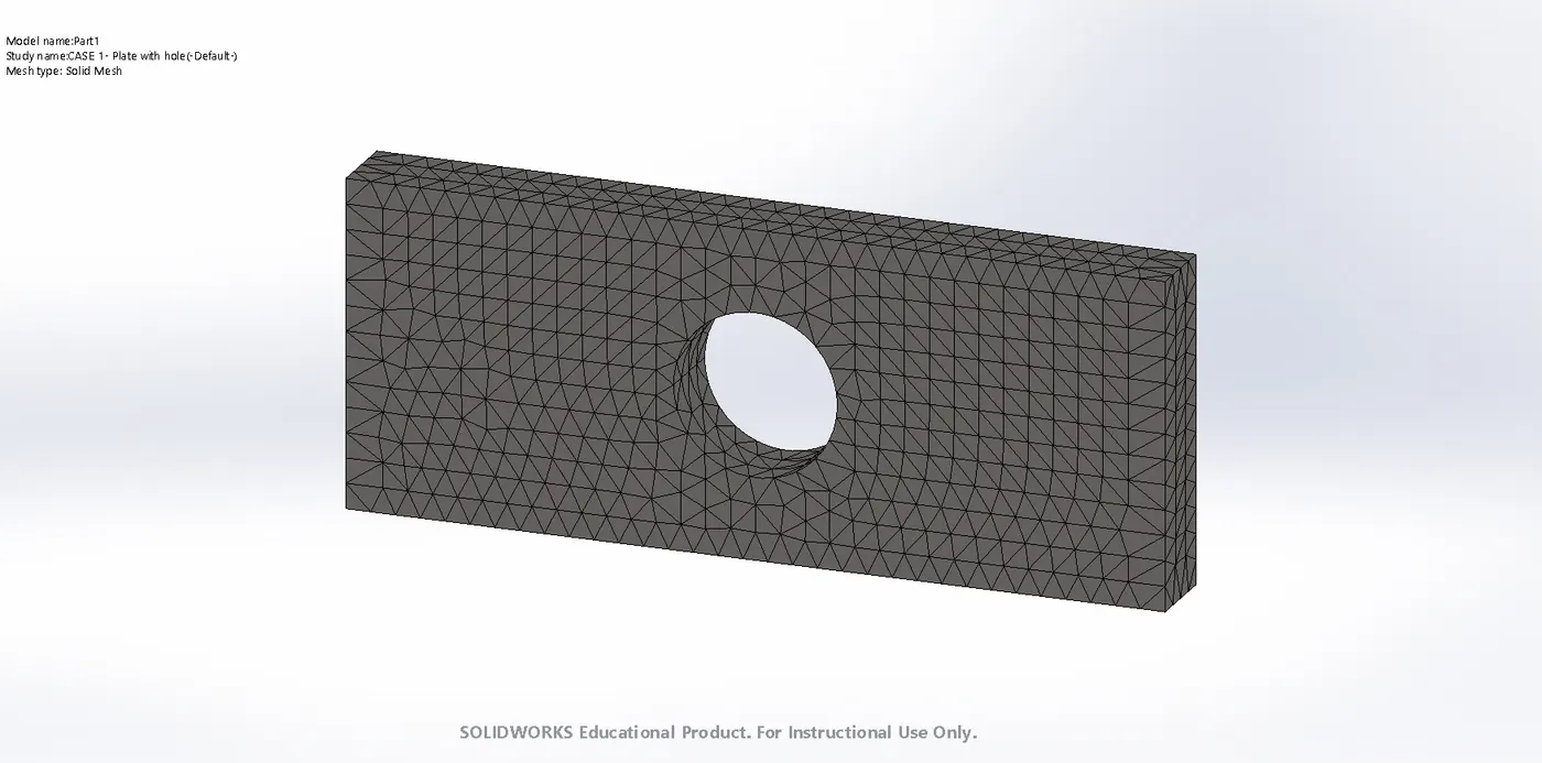
- A mesh is generated on the plate using the auto mesh tool, by setting the parameters for the Fine mesh. The mesh element size is around 9.5 mm after the complete development of the mesh on the plate.
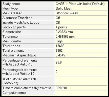
- The total nodes generated for mesh elements is 13609. The computational time taken for this complete meshing for 8502 elements is around 0.1 seconds.
CASE 2
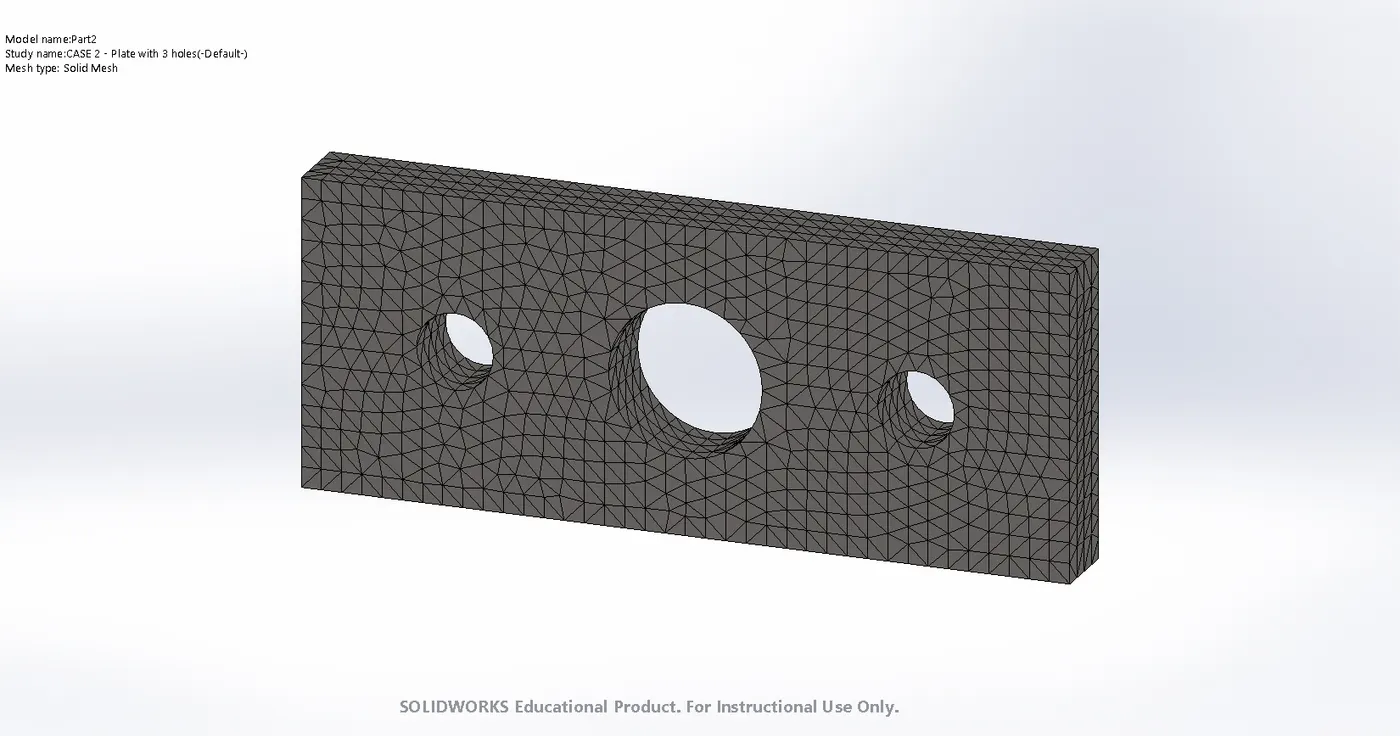
The Mesh is generated on the plate using the auto mesh tool, by setting the parameters for the Fine mesh. The mesh element size is around 8 mm after the complete development of the mesh on the plate.
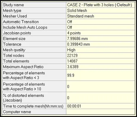
The total nodes generated for mesh elements is 22129. The computational time taken for this complete meshing for 14087 elements is around 0.1 seconds. The mesh generated is a solid mesh with high quality.
RESULTS :
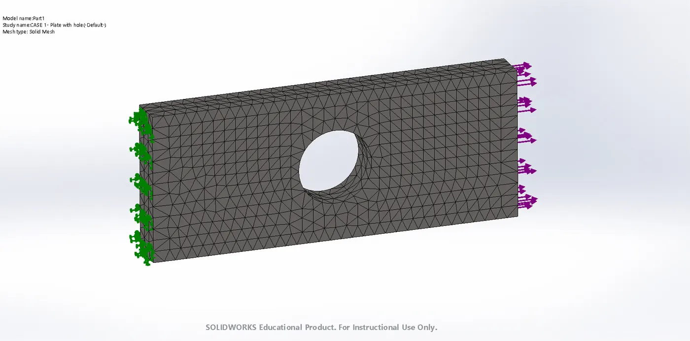
CASE 1 - Plate with single hole
CASE 2 - Plate with THREE holes
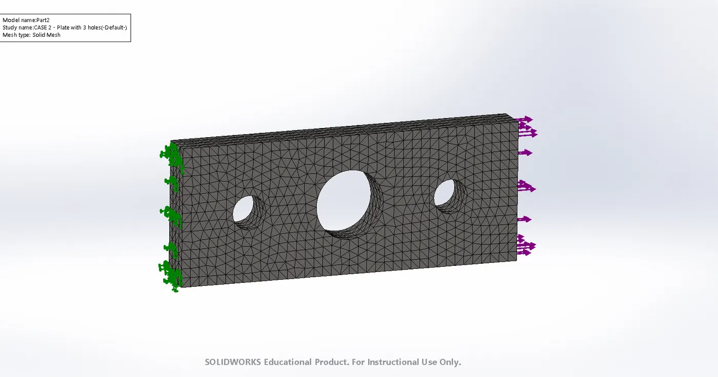
- The above images shows the model prepared after applying the boundary conditions on it for both the cases respectively.
STRESS
CASE 1
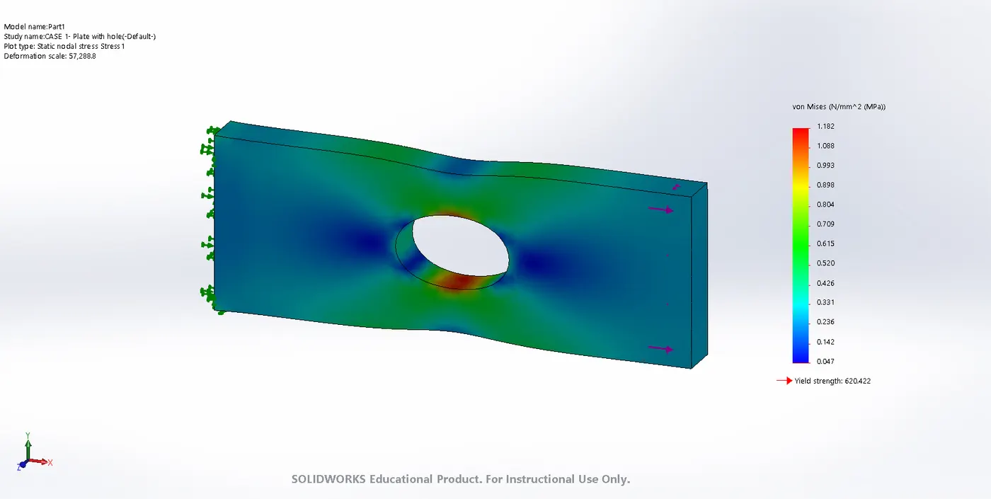
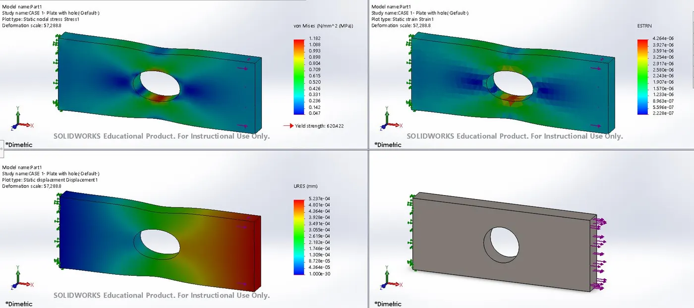
As, the plate with a hole is fixed from 1 end and a tensile load is applied on the other end, thus the tensile stresses are produced over the plate. The legend also known as plot on the right side of the plate model shows the magnitude of stress. The blue region on the plate and legend indicates the minimum value and the red region on the same tells about the maximum stress generated. Here, in the rectangular plate with a single hole the maximum stress is about 1.182 N/mm^2.
CASE 2
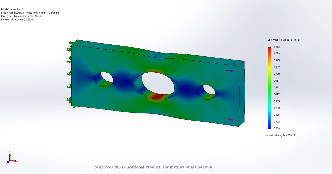
The legend also known as plot on the right side of the plate model shows the magnitude of stress. The blue region on the plate and legend indicates the minimum value and the red region on the same tells about the maximum stress generated. Here, in the rectangular plate with 3 holes the maximum stress is about 1.132 N/mm^2.
DISPLACEMENT
CASE 1
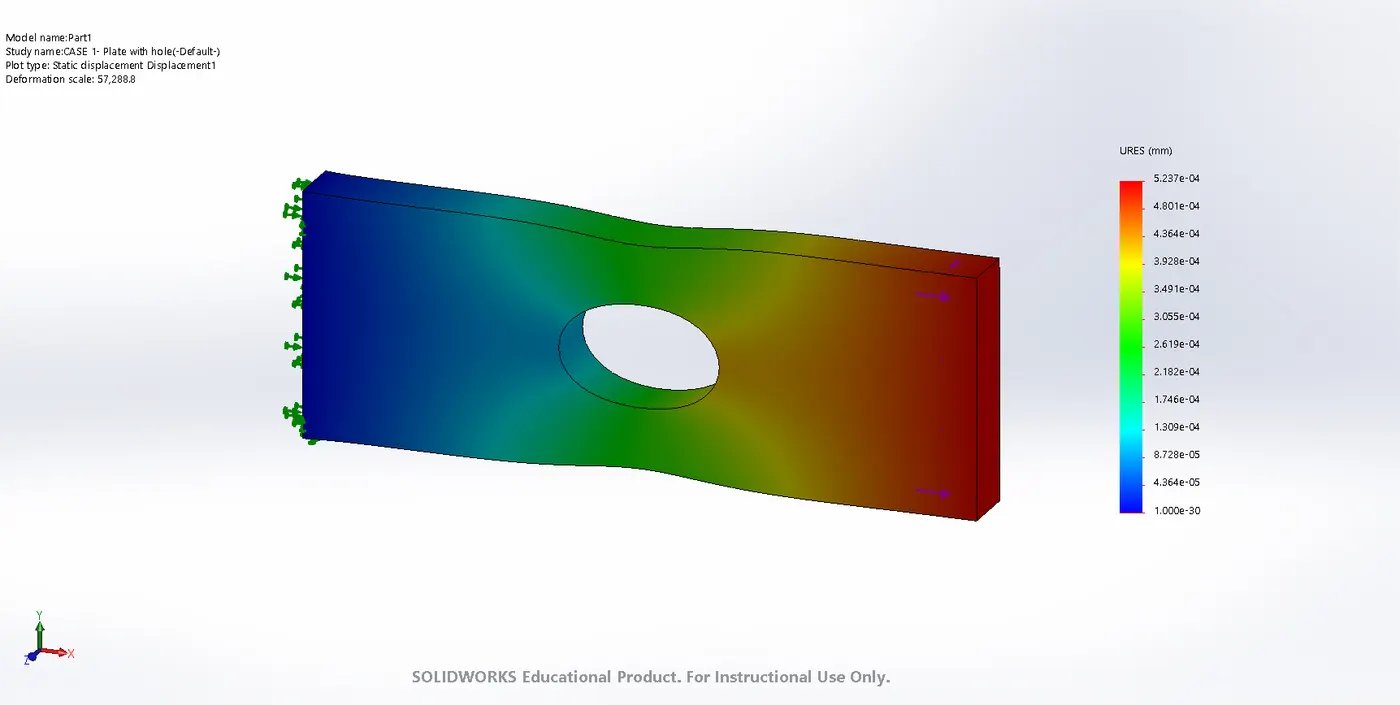
After applying the load of 1000N from an end of the plate with a single hole, the tensile stresses are generated. As, the tensile force is applied it pulls the free end of the plate by stretching it slightly which in short displaces it. The above image shows the change in displacement on the plate. The maximum displacement of the plate with a single hole is 5.237e-04 mm.
CASE 2
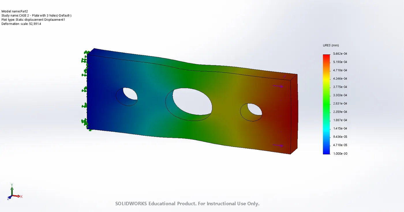
After applying the load of 1000N from an end of the plate with 3 holes, the tensile stresses are generated. As, the tensile force is applied it pulls the free end of the plate by stretching it slightly which in short displaces it. The above image shows the change in displacement on the plate. The maximum displacement of the plate with a single hole is 5.662e-04 mm.
STRAIN
CASE 1
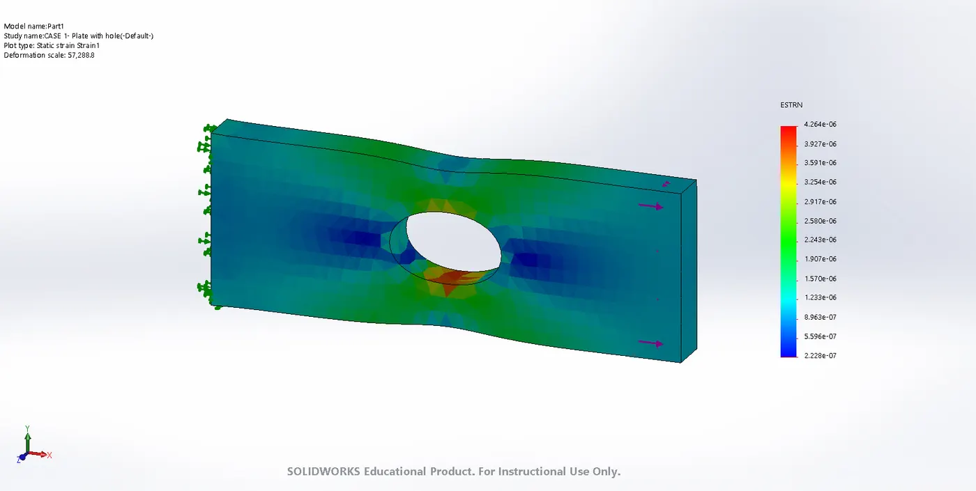
In the plate with single hole as the force is applied the plate gets deformed and thus, a certain amount of strain is developed in the plate. The above image shows the results of the strain generated with a minimum value indicated by blue region and the maximum value by red region. The maximum strain generated in the plate with a single hole is around 4.264e-06 near the hole.
CASE 2
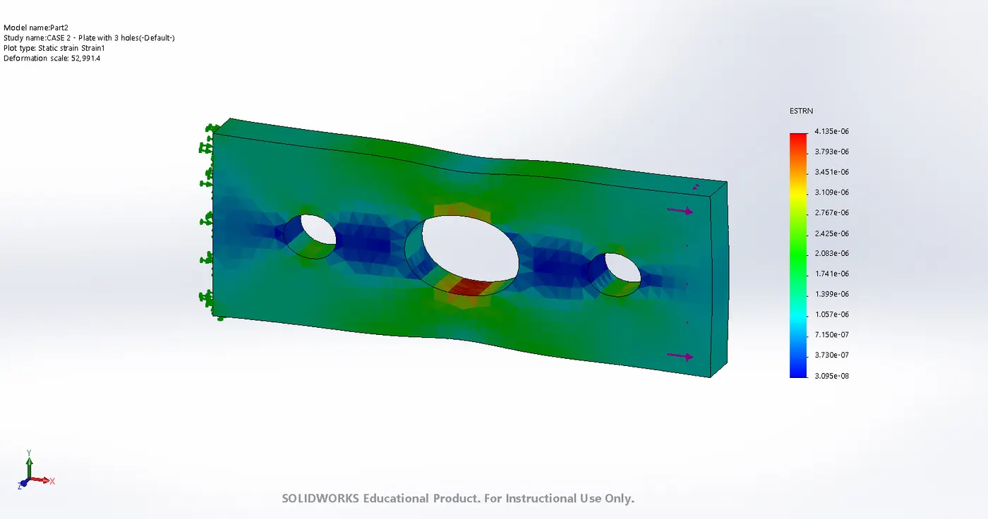
In the plate with 3 holes as the force is applied the plate gets deformed and thus, a certain amount of strain is developed in the plate. The above image shows the results of the strain generated with a minimum value indicated by blue region and the maximum value by red region. The maximum strain generated in the plate with 3 holes is around 4.135e-06 near the center hole.
OBSERVATION :
|
CASES |
Max. Stress (MPa) |
Max. Displacement (mm) |
Max. Strain |
|
1.Plate with single hole |
1.182 |
5.237e-04 |
4.264e-06 |
|
2.Plate with 3 holes |
1.132 |
5.662e-04 |
4.135e-06 |
- The above table represents the final results of static analysis for the two cases of plate with single hole and 3 holes. The maximum stress 1.182 is produced in case 1 whereas the maximum displacement is seen in case 2 for plate with 3 holes. The max. strain of around 4.264e-06 is developed in case 1 for plate with single hole.
COMPARISON OF RESULTS :
CASE 1
CASE 2
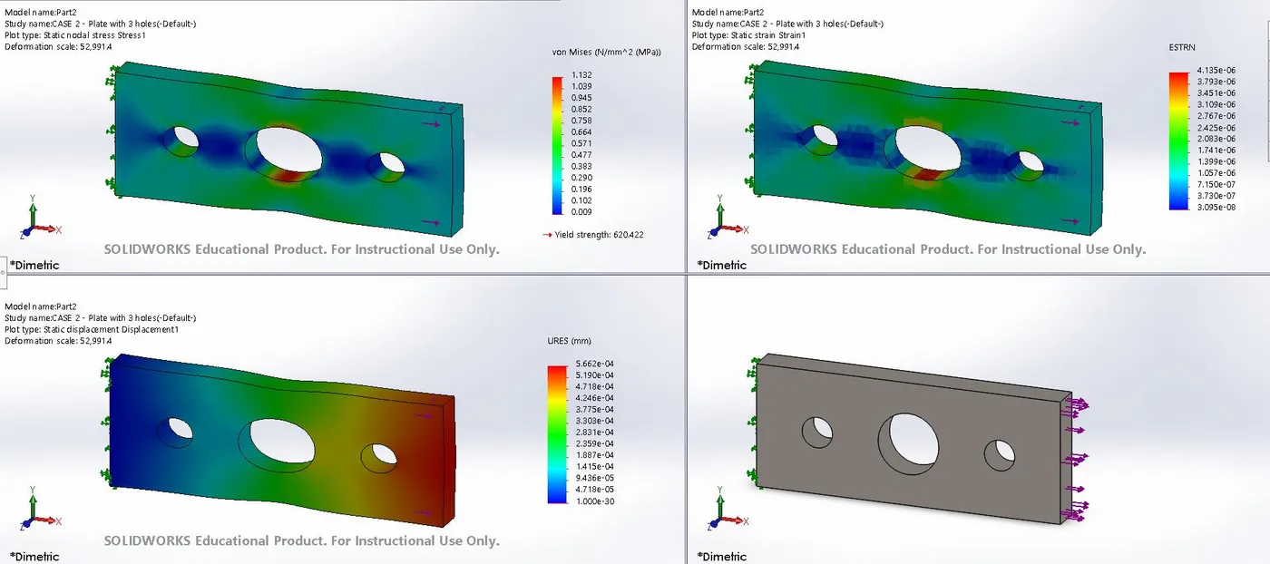
- In both the cases i.e rectangular plate with a single hole and the rectangular plate with 3 holes we had applied a tensile load of 1000 N on one end of plates and fixed the plate from another end. This causes the stress generation on the plates in case of plate with single hole maximum stress produced is 1.182 MPa whereas the stress produced in the plate with 3 holes for case 2 is 1.132 MPa. Here, the maximum stress variation is seen near the center hole of plate in both cases. But, in case 1 maximum stresses are generated than case 2 because in case 2 the plate has 2 more holes along with a center hole with distributes some stress along with the 2 holes rather than concentrating in the center hole with high magnitude.
- In the case 1 in plate with single hole the maximum displacement is 5.237e-04 mm whereas in case 2 the max. displacement is 5.662e-04 mm. In case 2 there are additional 2 holes with causes stress concentration and also, the removal of some material from the plate thus, this give rise to higher displacement in case 2 than case1. The maximum strain produced in the case 1 in plate with a single hole is 4.264e-06 and in case 2 for plate with 3 holes the max. strain developed is 4.135e-06 near the center hole. Thus, we conclude that the max. strain is developed after applying tensile load is in Case 1 for plate with single hole.
CONCLUSION :
Hence, we had broadly understood the concept of static analysis for a plate with single hole and the plate with three holes and the comparison of their varying output had also been analyzed. We get the max. stress and strain in case 1 but, max. displacement in case 2 due to its different cross section and some other parameters which we had understood completely in this project.
ANIMATION -
References –