Frequency Analysis of a rotating shaft
AIM :
To perform frequency analysis for a rotating shaft with disc in solidworks.
OBJECTIVE :
- Conduct a frequency analysis on the rotating shaft with disc.
- Determine the 5 different mode shapes and display its resonant frequencies.
INTRODUCTION :
- The goal of modal analysis in a model is to determine the natural mode shapes and frequencies of an object or structure during free vibration.
- It is common to use the finite element method (FEM) to perform this analysis because, like other calculations using the FEM, the object being analyzed can have arbitrary shape and the results of the calculations are acceptable.
THEORY :
- Resonance describes the phenomenon of increased amplitude that occurs when the frequency of a periodically applied force is equal or close to a natural frequency of the system on which it acts.
- When an oscillating force is applied at a resonant frequency of a dynamical system, the system will oscillate at a higher amplitude than when the same force is applied at other, non-resonant frequencies.
- Frequencies at which the response amplitude is a relative maximum are also known as resonant frequencies or resonance frequencies of the system.
Types of Solver in solidworks for frequency analysis are –
- Direct sparse solver
- FFEPLUS
- Intel direct sparse
PROCEDURE :
- Create a 2 D sketch of the shaft with a disc of certain dimensions and then convert it into 3D model by using a particular feature in solidworks.
- Next, step is to go for simulation, so select the type of analysis, in our case we choose frequency analysis to perform.
- Apply the material to the Shaft with disc part model.
- Apply the fixtures to the shaft at its end to hold while performing analysis.
- Create a Mesh on the model using mesh tools.
- Run the simulation and get the results for 5 different modal shapes with frequency.
CASE SETUP :
PART MODELLING :
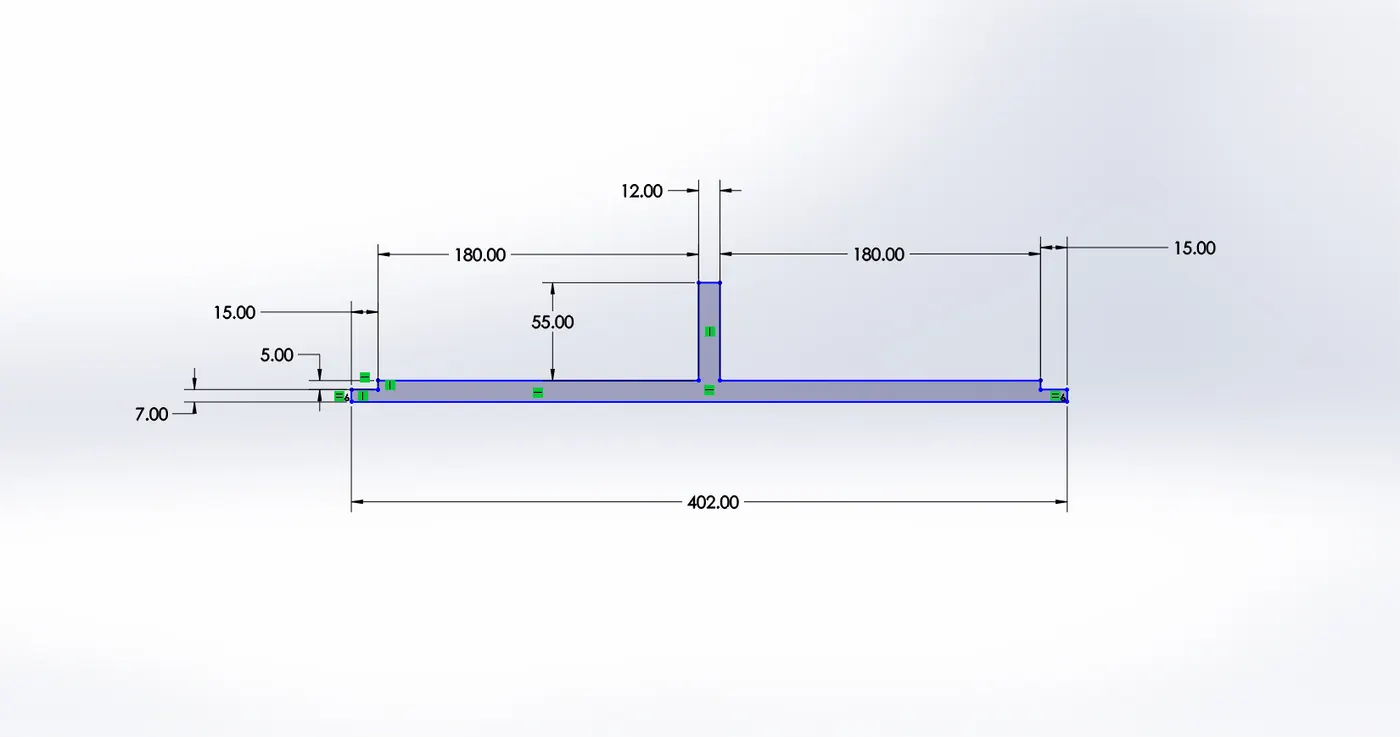
- Created a 2 D sketch of various dimensions as shown in above image for the shaft with a disc.
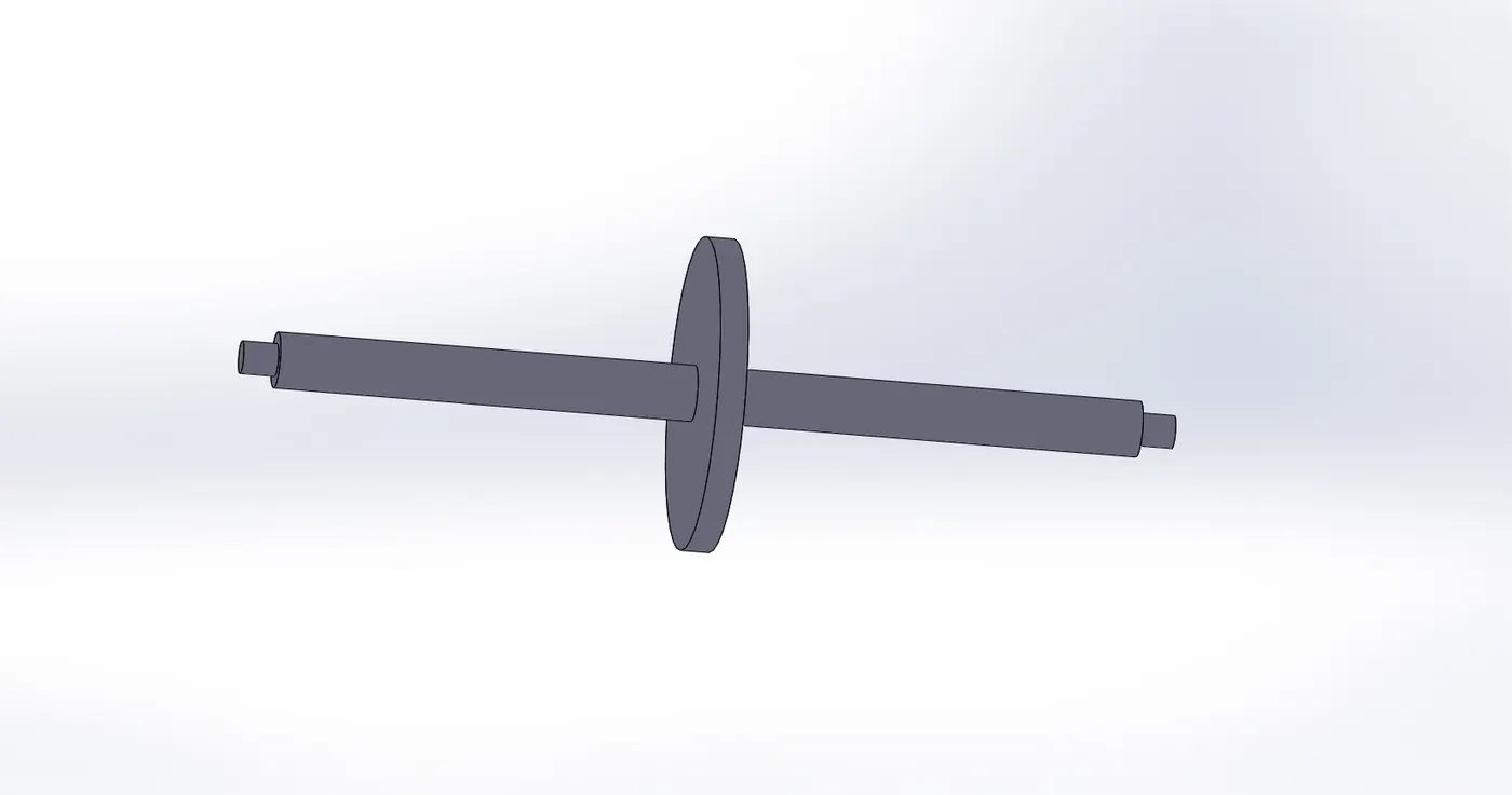
- Convert it into the 3D model by using a feature known as Revolve tool in solidworks by rotating the upper half 2D sketch into 360 deg.
MATERIAL :
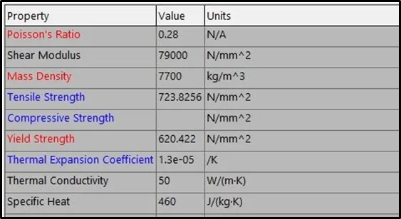
- The material selected is Alloy steel which has yield strength of 640.422 MPa. To apply the material simply select the part and click on apply material option then select the type of material needs to be applied and then click on apply.
FIXTURE :
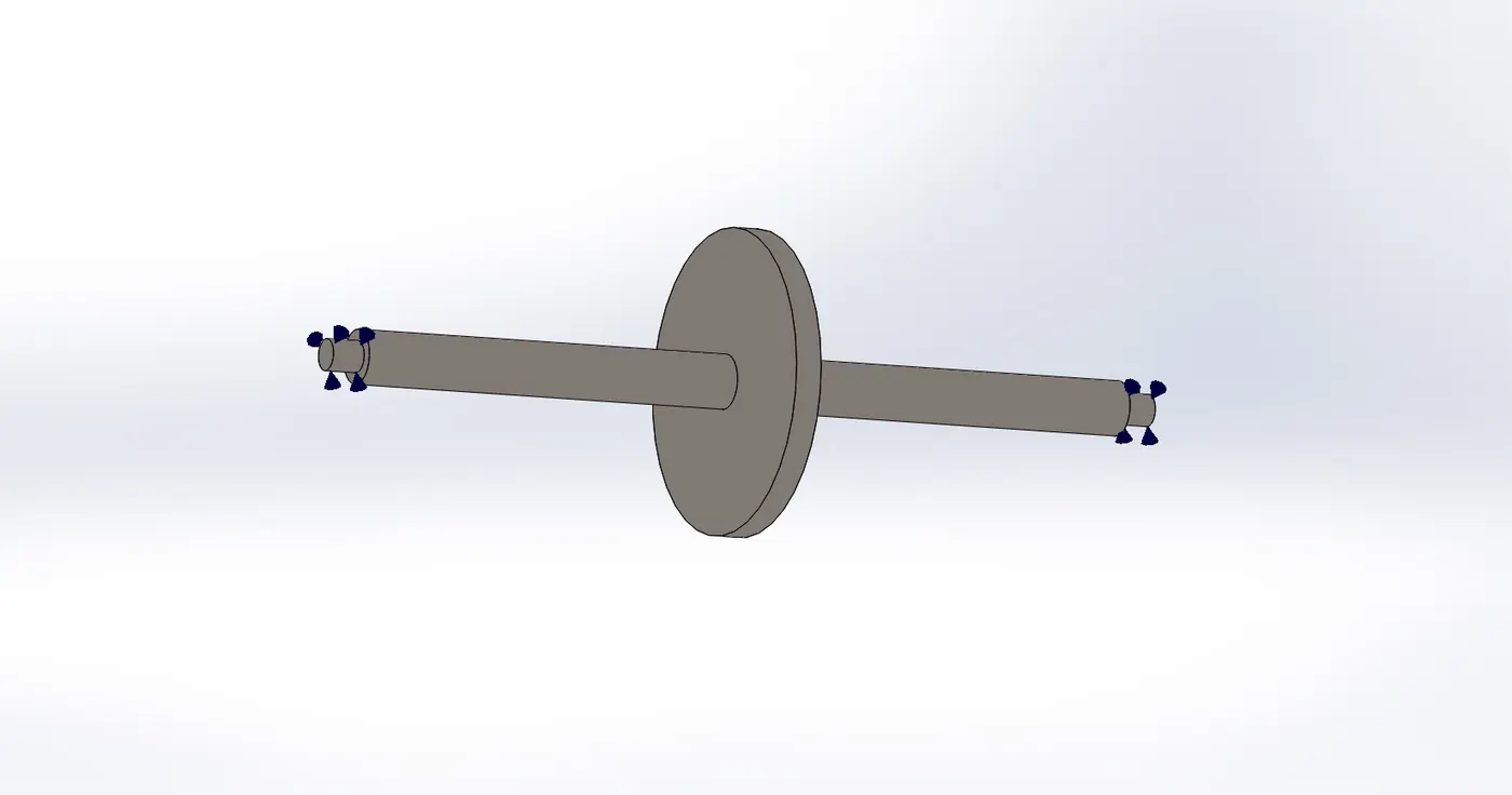
- A fixture is necessary to apply for this case of shaft with disc to hold it for support. Here, the bearing fixture is applied on the stepped face of the shaft on both its end. Applied fixture is shown in figure in the above image respectively.
MESH :
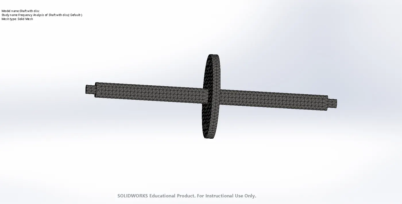
- A mesh is created using a auto mesh tool with a High quality mesh. The mesh size of the elements after generation of complete mesh is around 6mm.
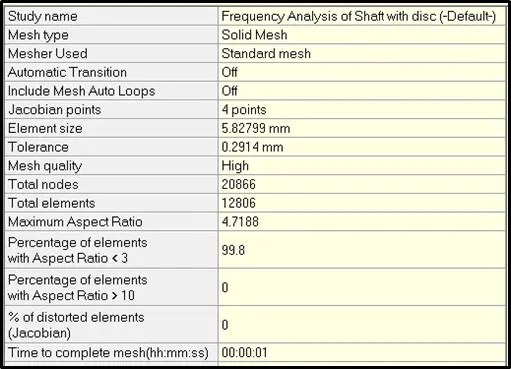
- This solid type mesh is generated with total 12806 elements and 20866 nodes. The computational time required for the meshing is about 0.1 seconds.
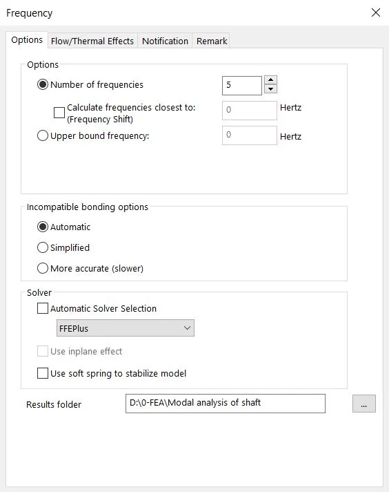
- The above image shows the properties of the FEA used for this analysis. Here, we had used FFEPlus solver and 5 no. of frequencies to perform anlaysis for shaft with disc.
RESULTS :
MODE SHAPE 1
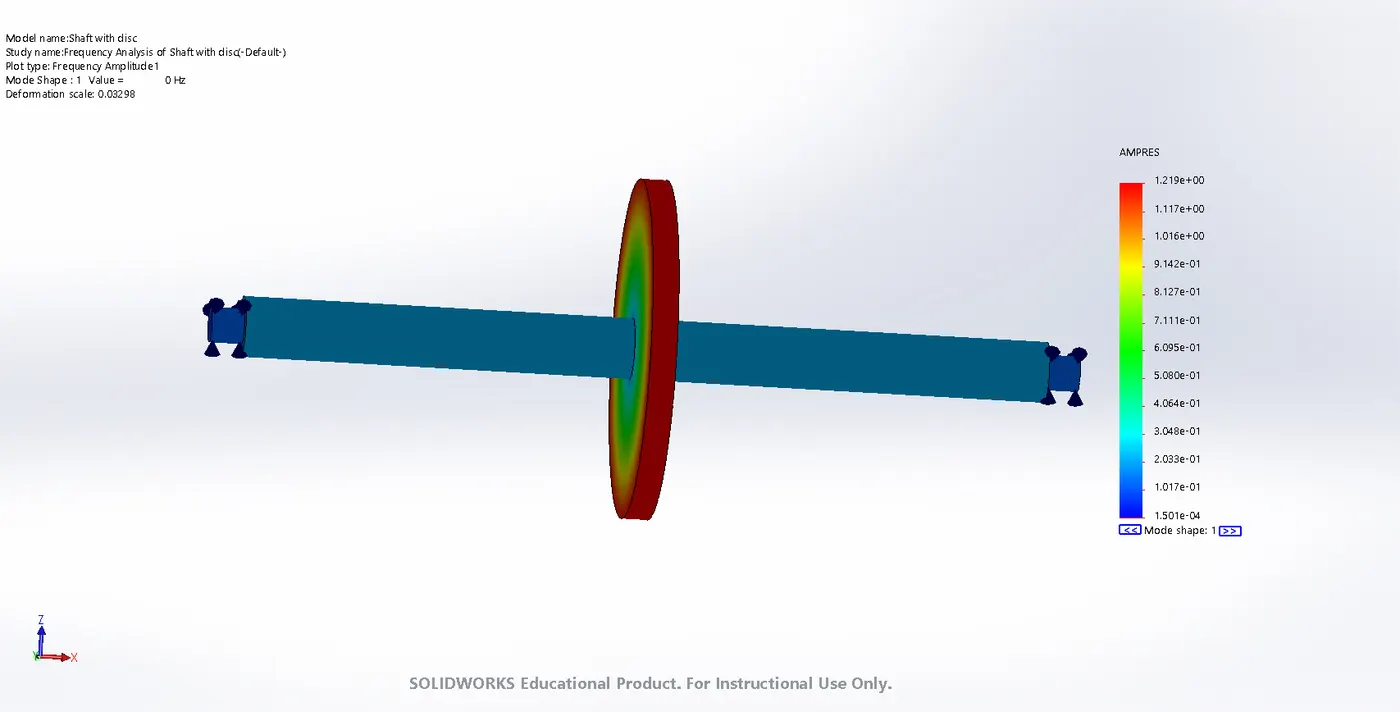
- The mode shape 1 has a varying amplitude which can be seen in the legend on right side of model and also on the shaft with disc model which is indicated by the blue region for minimum amplitude and red region for maximum amplitude. The maximum amplitude for this mode shape is 1.219e+00.
MODE SHAPE 2
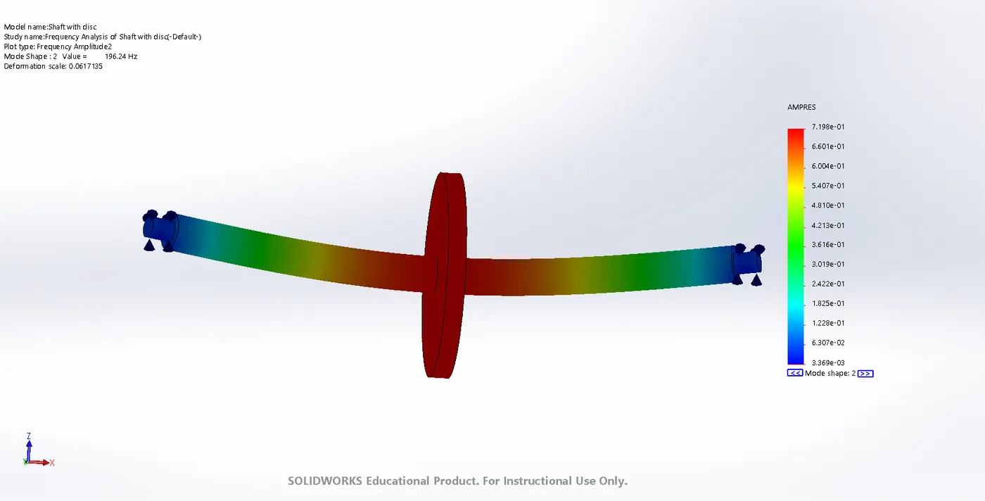
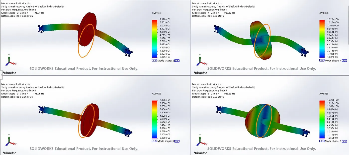
- The mode shape 2 has a varying amplitude which can be seen in the legend on right side of model and also on the shaft with disc model which is indicated by the blue region for minimum amplitude and red region for maximum amplitude. The maximum amplitude for this mode shape is 7.198e+01.
MODE SHAPE 3
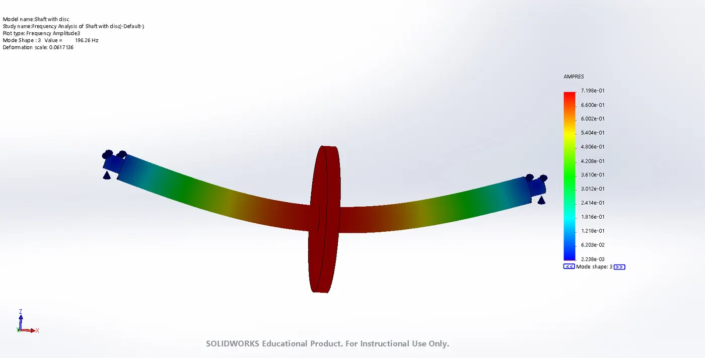
- The mode shape 3 has a varying amplitude which can be seen in the legend on right side of model and also on the shaft with disc model which is indicated by the blue region for minimum amplitude and red region for maximum amplitude. The maximum amplitude for this mode shape is 7.198e+01.
MODE SHAPE 4
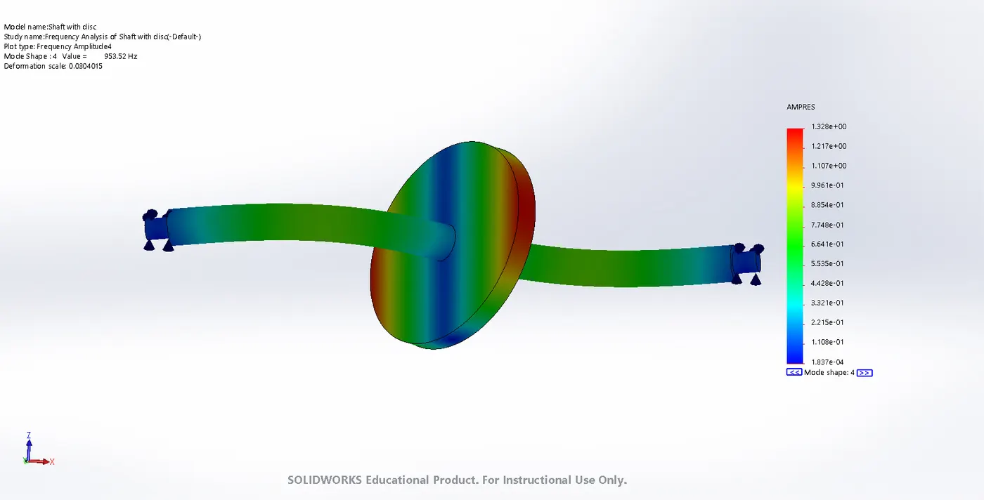
- The mode shape 4 has a varying amplitude which can be seen in the legend on right side of model and also on the shaft with disc model which is indicated by the blue region for minimum amplitude and red region for maximum amplitude. The maximum amplitude for this mode shape is 1.328e+00.
MODE SHAPE 5
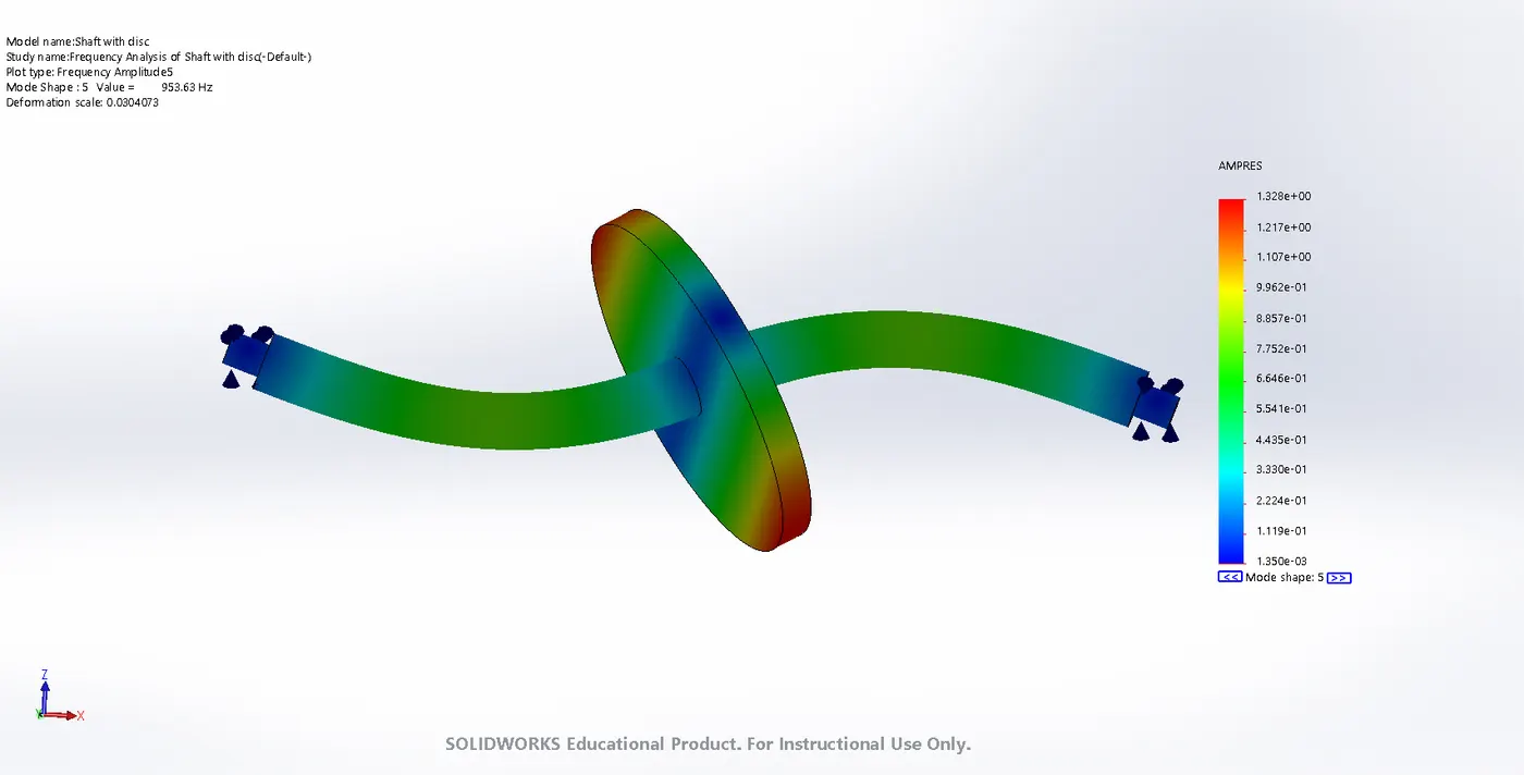
- The mode shape 5 has a varying amplitude which can be seen in the legend on right side of model and also on the shaft with disc model which is indicated by the blue region for minimum amplitude and red region for maximum amplitude. The maximum amplitude for this mode shape is 1.328e+00.
COMPARISON of 2-4 Mode Shapes -
OBSERVATION :
|
Mode Shape |
Minimum Amplitude |
Maximum Amplitude |
|
1. |
1.501e-04 |
1.219e+00 |
|
2. |
3.369e-03 |
7.198e+01 |
|
3. |
2.238e-03 |
7.198e+01 |
|
4. |
1.837e-04 |
1.328e+00 |
|
5. |
1.350e-03 |
1.328e+00 |
- The above table represents the varying amplitude for frequency analysis. The maximum amplitude for made shape 1 is 1.219e+00 and minimum 1.501e-04. For mode shape 2 and 3 we have same maximum amplitude i.e. 7.198e+01 but, different minimum amplitude i.e. 3.369e-03 amplitude for shape 2 and 2.238e-03 amplitude for shape 3 with displacement in different direction. The mode shape 4 and 5 also had same value for maximum amplitude but, different minimum amplitude i.e. 1.837e-04 amplitude for shape 4 and 1.350e-03 amplitude for shape 5 with displacement in different direction. The maximum amplitude among along shapes is in mode shape 2 and 3 displacing each in separate directions.
|
Mode No. |
Frequency (Rad/sec) |
Frequency (Hertz) |
Period (Seconds) |
|
1 |
0 |
0 |
1e+32 |
|
2 |
1233 |
196.24 |
0.0050959 |
|
3 |
1233.1 |
196.26 |
0.0050953 |
|
4 |
5991.2 |
953.52 |
0.0010487 |
|
5 |
5991.8 |
953.63 |
0.0010486 |
- The above table represents the resonant frequencies by showing various frequency values of all 5 made shapes in rad/sec and in hertz along with the time for period in seconds. In mode shape 1 we got 0 hertz, while the frequency for mode shape 2 and 3 are almost same frequency that is 196.24 and 196.26 hertz. The maximum frequency for mode shape 3 and 4 is 953.52 hertz and 953.63 hertz respectively.
CONCLUSION :
- In this project, we had broadly understood all about the frequency analysis and the procedure to conduct it. Here, we can conclude that we got the final results for 5 mode shapes of shaft with disc with different resonant frequencies and the maximum frequency is in mode shape 5 i.e 953.63 hertz respectively.
ANIMATION :
The below video represents the animation for change in frequencies for mode shape 2 of shaft with disc.
References –