Boeing-747 _ Final_Project of Boeing
BOEING-747
OBJECTIVE:
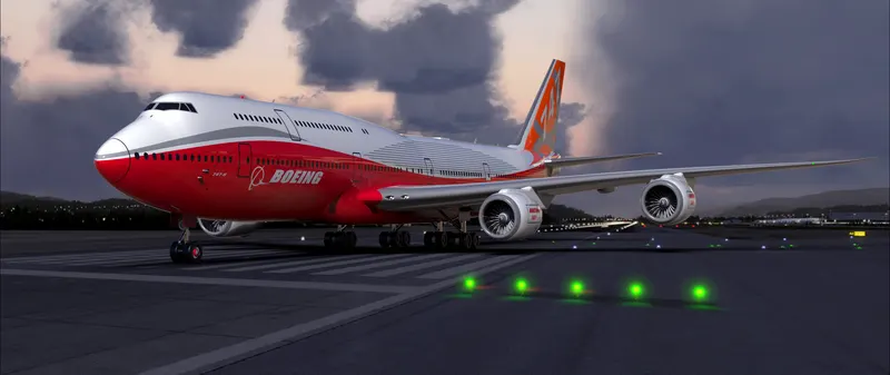
Creating a boeing-747 full body structure using the 2D sketch entities and 3D feature and assemble the all parts with realistic rendering.
INTRODUCTION:
The Boeing 747, commonly called a Jumbo Jet, is among the most recognizable jet airliners and is the largest passenger airliner currently in service.
Type - Airliner
Manufacturer - Boeing
Maiden flight - 1969- 02-09
Introduced- 1970- 01-22 with Pan American World Airways and Trans
Primary user - Japan Airlines (60)
British Airways - (57)
Number built - 1375 as of 2006
Unit cost - 747-400 $230,000,000 (2006)
DESIGNING PROCESS:
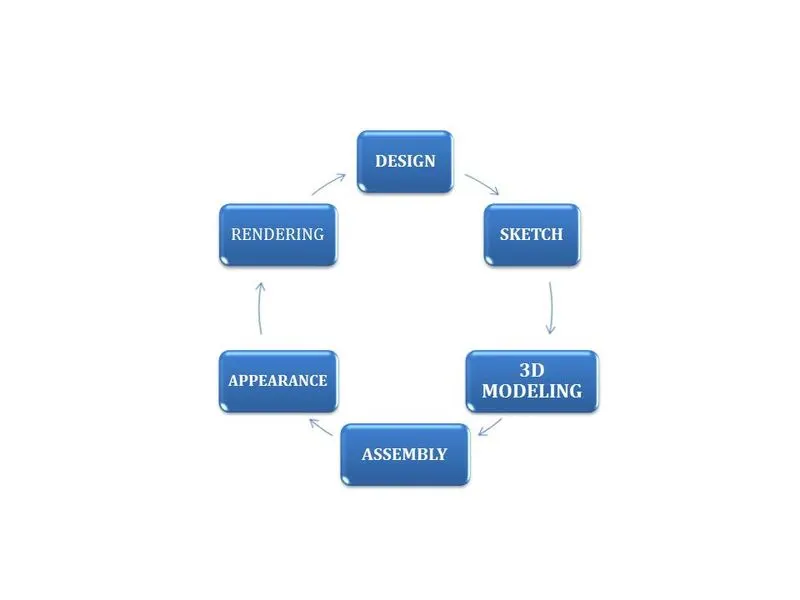
Sketch Entities:
- Line, circle, rectangle, arc, slot, spline.
- Convert entities- Create one or more curves in a sketch by projecting an edge, loop, face, curve or set of sketch curves on to the sketch plane.
- Trim and extend- cut the point over the sketch entity and move the point over the sketch entity to extend.
- Offset-offset line arc and splines if the original entity change the offset entity also change.
- Mirror- mirroring is another way that can create copy of an existing object choosing a plane or mirror face.
- Pattern- create multiple instances of one are more features that can space alone with pattern type.
Solid features:
- Boss Extrude = It is converting 2D sketch into 3D feature
- Cut extrude = cut extrude is similar to boss extrude but the difference it is cutting the 3D feature
- Sweep = Sweep features are defined by using custom 2D cross-section (or face) moved along a pre-set path to create a 3D shape or surface.
- Loft-Loft feature creates a shape by making transitions between multiple profile and guide curves. this tool is very valuable for modelling complex surface
- Revolve = Revolves add or remove material by revolving one or more profiles around a centreline.
- Shell =The shell tool hollows out a part, leaves open the faces you select, and creates thin-walled features on the remaining faces.
- Mirror = mirroring is another way that can create copy of an existing object choosing a plane or mirror face
Surface feature:
- Surface extrude = Using the Surface Extrude feature, it can extrude the boundary edges of a face or edges of a surface body in a customized direction.
- Surface trim = Create two or more surfaces that intersect at one or more points, or create a surface that intersects with a plane or has a sketch on its face.
- Thicken = Thicken takes a surface body (which has zero thickness) and makes it a solid by specifying a thickness value and side to thicken.
Common feature:
- Plane - Plane is reference for sketching and creating features.
- Curves - Curve as the path or guide curve for a sweep and loft feature, as a parting line for a draft feature.
- Dome - It creates a dome that is tangent to the adjacent cylindrical or conical face.
- Fillet - Create a rounded internal or external face on the part. selected faces, edges or edge loops.
- Split-use the split feature to create multiple parts from an existing part.
- Combine - Multiple bodies contained within one multibody part file.
- Split line - Tool projects an entity (sketch, solid, surface, face, plane, or surface spline) to surfaces, or curved or planar faces.
Assembly:
- Assembly is the process of combining individual components into product.
- can create assemblies using bottom-up design, top-down design, or combination of both methods.
- using mates for assembly process.
- Assembly → insert part→ select a base part→ fix the part→ connect all the part using mates→ save the assembly.
BOEING 747 PARTS:
- Blueprints
- Fuselage
- Belly fairing
- Nose cone
- Pitot tubes
- Cockpit window
- Passengers window
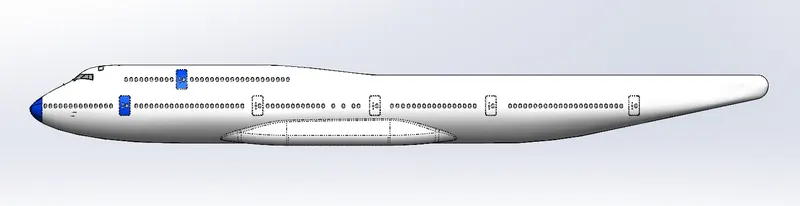
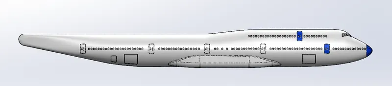
- Door & hatches
- Light & antenna
- Auxiliary power unit
- Vertical stabilizer
- Wing
- Flap & aileron
- Flap track fairing
- Landing gear hatches
- Wheel
- Nose gear
- Main gear
- Engine
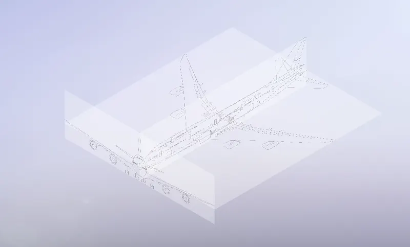
Blueprints
- Start a sketch on the front plane by right click in the front plane click sketch's icon.
- Click in TOOLS after that click in Sketch Picture.
- Open the front view of blueprint yacht.
- Send the properties of the sketch picture to move this image to correct position.
- Make the Transparency of the image in 0.30.
- This is the same procedure for all the other view of blueprints.
Fuselage
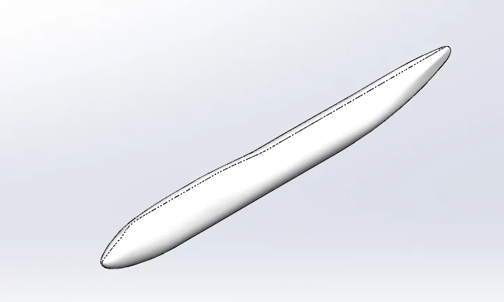
- The fuselage, or body of the airplane, is a long hollow tube which holds all the pieces of an airplane together.
- The fuselage is hollow to reduce weight. As with most other parts of the airplane, the shape of the fuselage is normally determined by the mission of the aircraf.
Feature used
- Sketch entities
- Surface loft
- Mirror
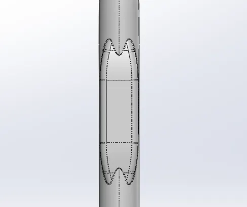
Belly fairing
- Belly fairing. Also called a “ventral fairing”, it is located on the underside of the fuselage between the main wings. It can also cover additional cargo storage or fuel tanks.
Feature used
- Boss Extrude
- Fillet
- Split line
- Mirror
- Combine
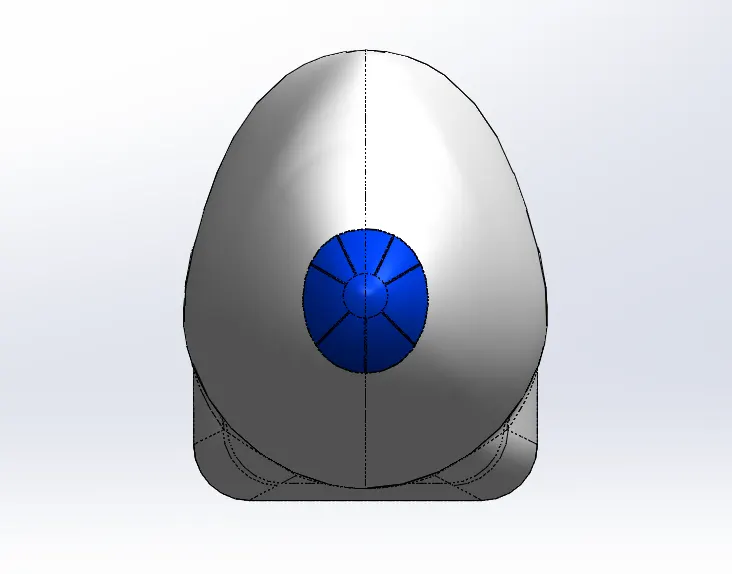
Nose cone
- The nose of an airplane is very important to flight. Like the tip of an arrow, it decides where the plane is going to go.
- All of the elements of flight depend on keeping the nose pointed in the right direction.
Feature used
- Split line
- Sweep
- Mirror
- Fillet
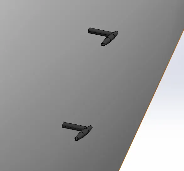
Pitot tubes
- Pitot tubes are crucial components onboard aircraft used to measure a range of important data.
- The tubes are popularly known as speedometers.
Feature used
- Boss Extrude
- Cut extrude
- Fillet
- Mirror
- Chamfer
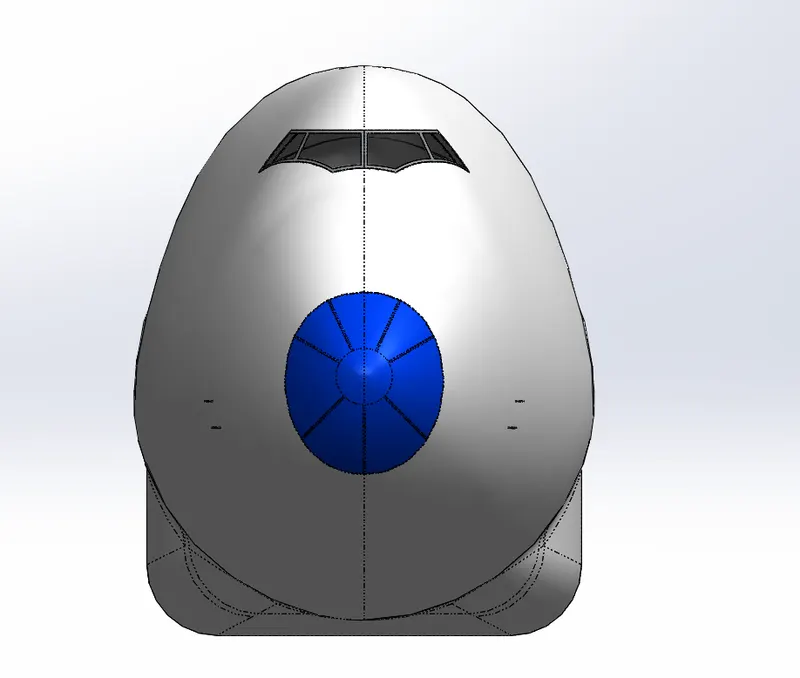
Cock pit window
- Boeing windows aren’t made from your run of the mill glass.
- Instead, they are constructed from special polymers and plastic.
Feature used
- Split line
- Surface offset
- Thicken
- Fillet
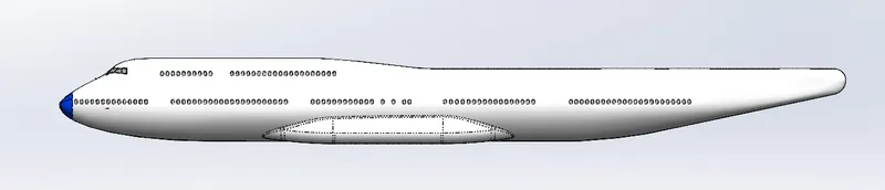
Passenger windows
- many passenger cabin windows, flight deck windows are built with multiple plies of glass or stretched acrylic material.
Feature used
- Split line
Door & hatches
Feature used
- Split line
- Linear pattern
- Surface offset
- Thicken
- Fillet
Light & antenna
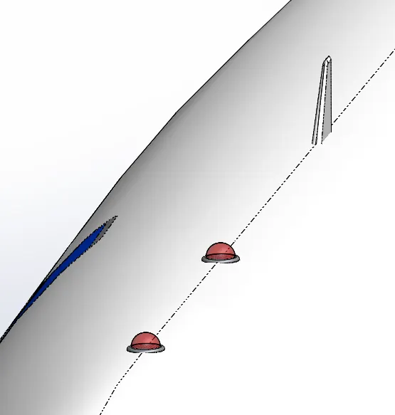
- The red and green lights found on the wingtips of airplanes are known as navigation lights.
- They are designed to increase the airplane's visibility to other pilots, as well as air traffic controllers on the ground, to minimize the risk of collision. Navigation lights don't emit any signals.
- The antenna at the transmitter generates the radio wave.
- A voltage at the desired frequency is applied to the antenna.
- The voltage across the antenna elements and the current through them create the electric and magnetic waves, respectively.
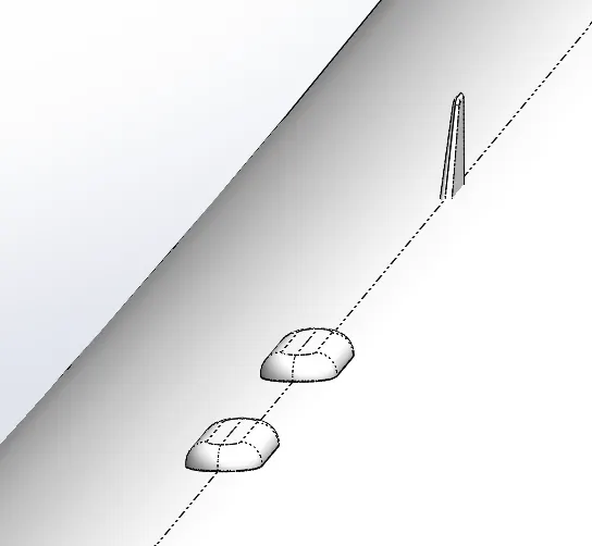
Feature used
- Revolve
- Linear pattern
- Boss extrude
- Draft
- Split line
- Surface offset
- Thicken
- fillet
Auxiliary power unit
- An auxiliary power unit (APU) is a device on a vehicle that provides energy for functions other than propulsion.
- It provides bleed air for cabin conditioning from a low spool-driven load compressor, and electrical power from two gearbox-mounted 90kVA generators.
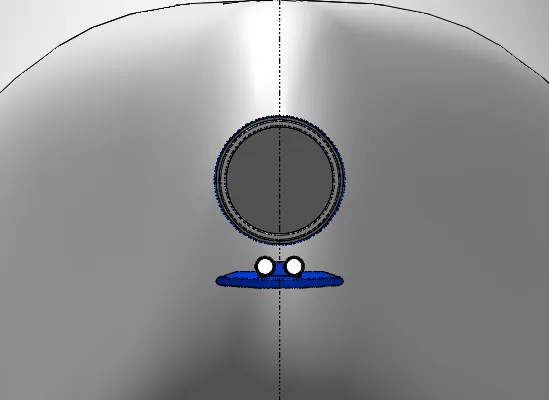
Feature used
- Cut extrude
- Boss extrude
- Split line
- Surface offset
- Thicken
- Mirror
- Fillet
Vertical & Horizontal stabilizer
- The stabilizer is a fixed wing section whose job is to provide stability for the aircraft, to keep it flying straight.
- The horizontal stabilizer prevents up-and-down, or pitching, motion of the aircraft nose.
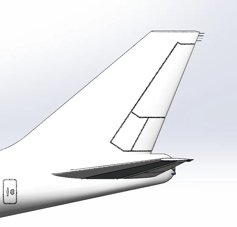
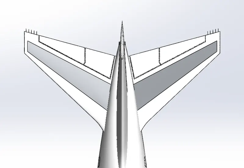
Feature used
- Loft
- Boss extrude
- Cut extrude
- Surface offset
- Thicken
- Fillet
- Mirror
Wings
- The wings generate most of the lift to hold the plane in the air.
- To generate lift, the airplane must be pushed through the air.
- The air resists the motion in the form of aerodynamic drag.
- Modern airliners use winglets on the tips of the wings to reduce drag.
- The turbine engines, which are located beneath the wings, provide the thrust to overcome drag and push the airplane forward through the air.
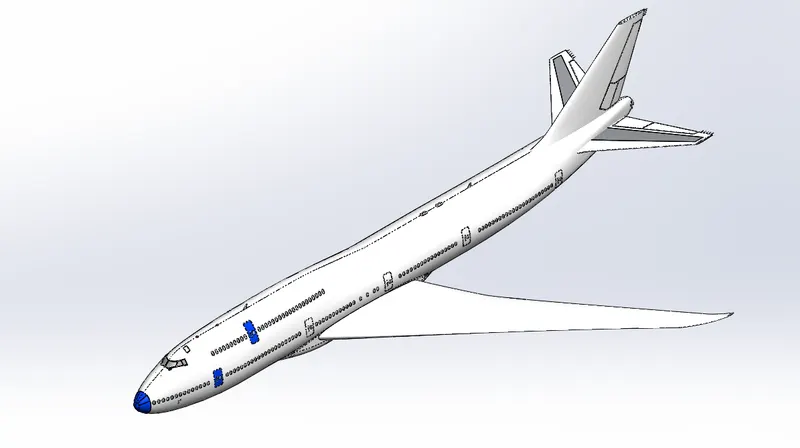
Feature used
- Loft
- Surface offset
- Surface cut
- Fillet
Flaps & Ailerons
- Flaps are deployed downward on take off and landing to increase the amount of force produced by the wing. On some aircraft, the front part of the wing will also deflect.
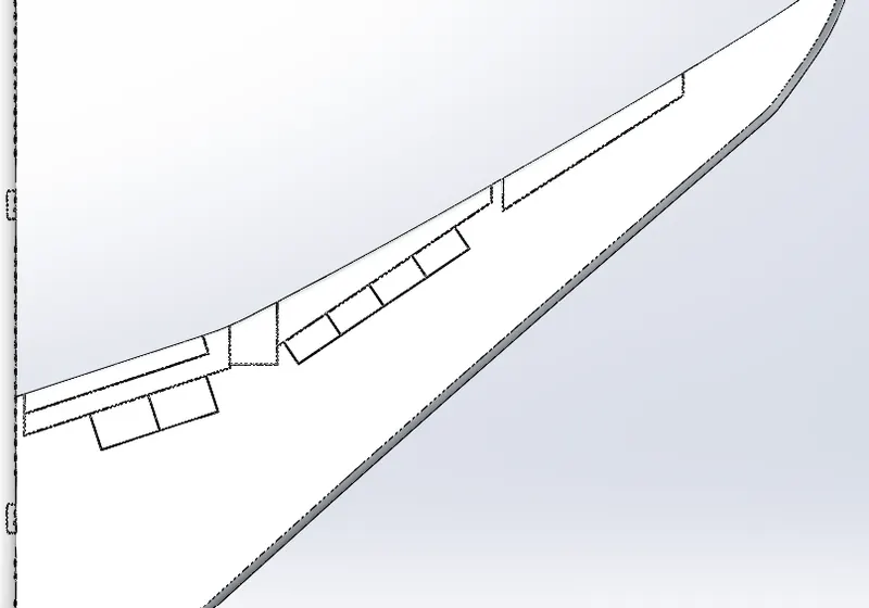
Feature used
- Cut extrude
- Split line
- Surface offset
- Thicken
- Fillet
Flap track fairing
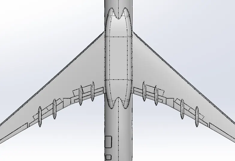
Feature used
- boss extrude
- split
- combine
- fillet
- mirror
landing gear hatches closed & open
Feature used
- split line
- surface offset
- Thicken
- Thicken
- Cut extrude
- Surface sweep
- Fillet
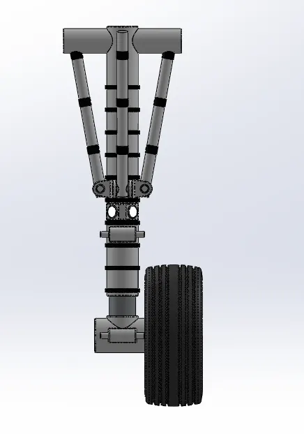
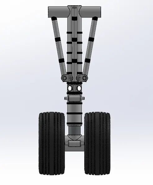
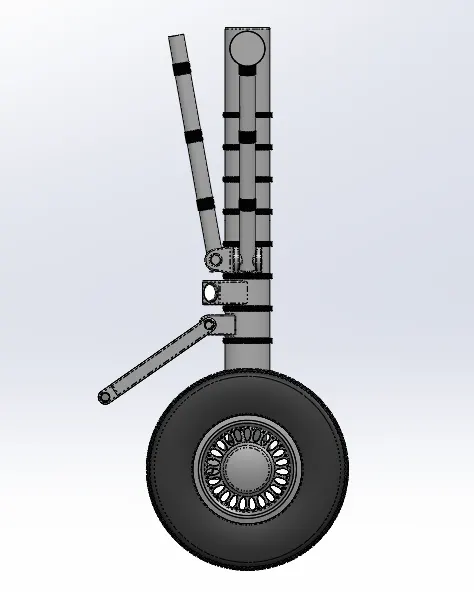
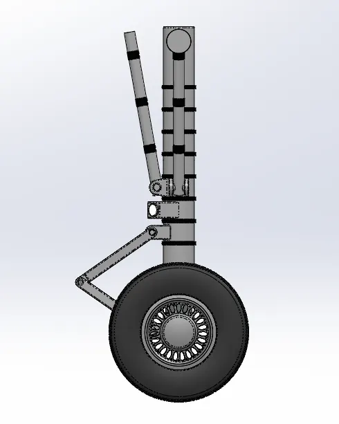
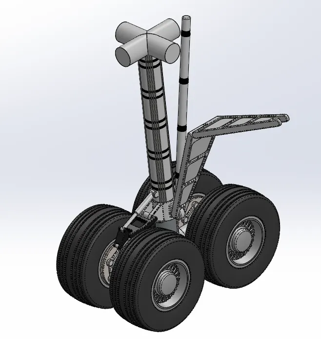
Nose gear
- The landing gear in the nose of an aircraft is called the nose gear.
- Nose gear is the name given to the landing gear in the nose of an airplane.
- In any type of airplane that has a tricycle type of landing gear, the wheel, tire and components in the front of the plane are referred to as nose gear.
Nose gear sub assembly
Step 1
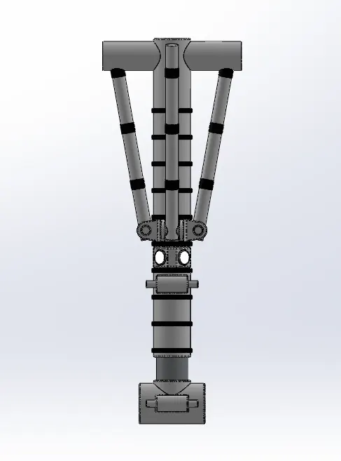
Step 2
Step 3
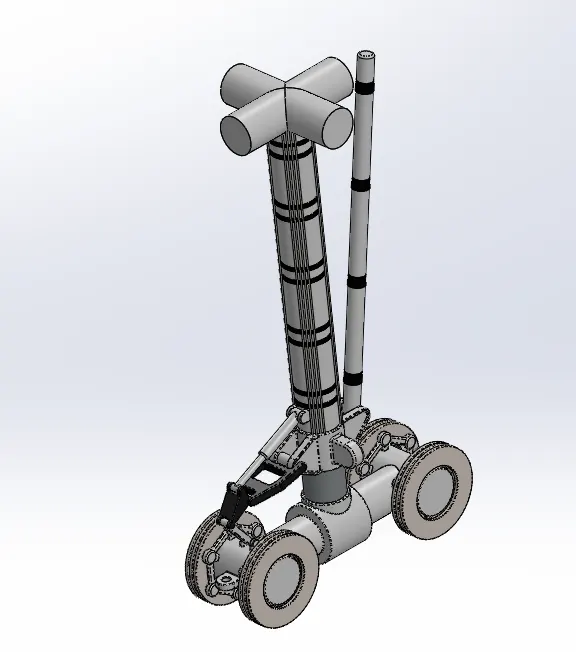
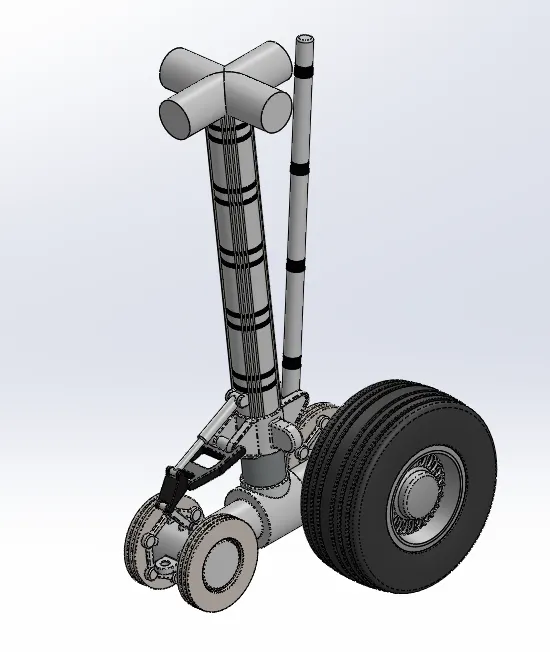
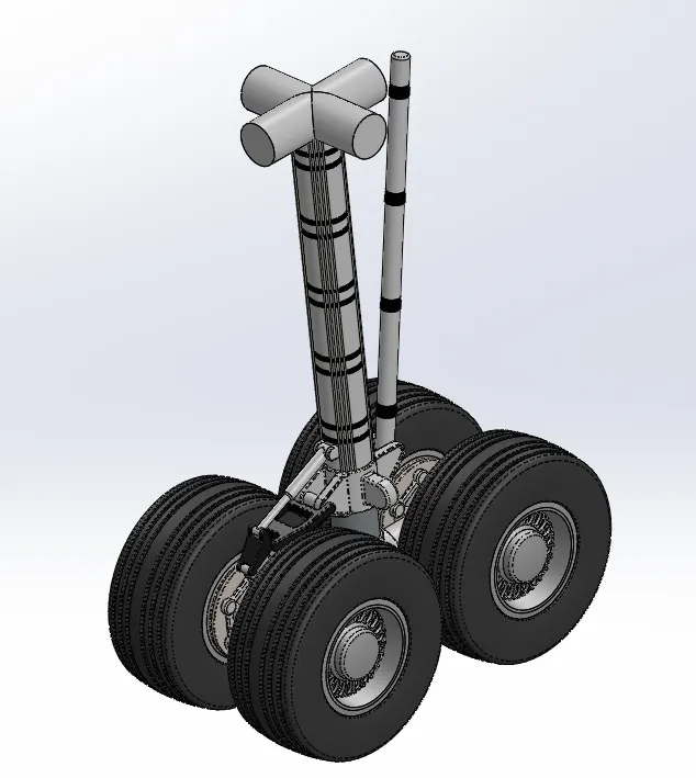
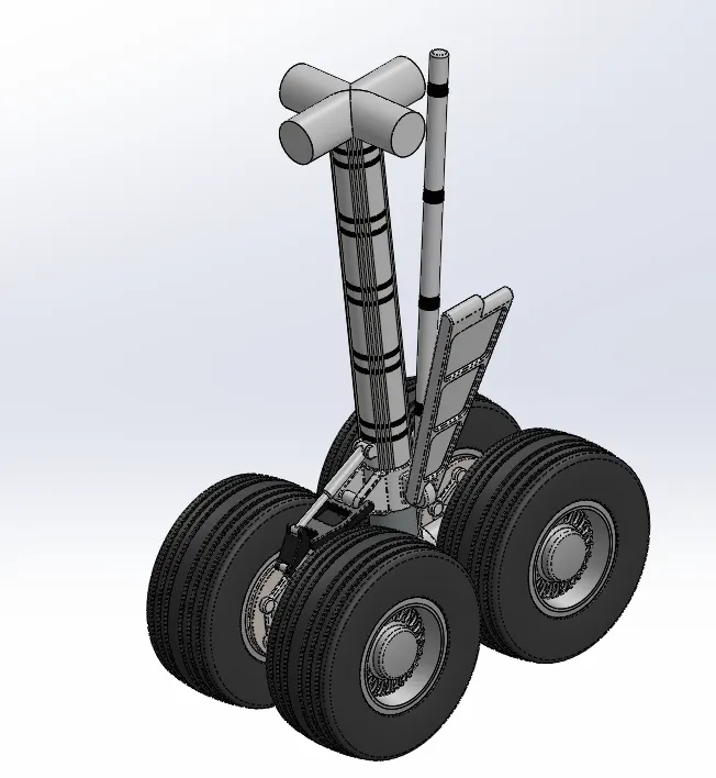
Main gear
- Landing gear, the principal support of the airplane during landing, mainly consists of the shock absorber, wheel, brake system, turning system, undercarriage retractile system, etc.
- It is used to absorb the landing impact energy so as to minimize the loads transmitted to the airframe
Main gear sub assembly
Step 1
Step 2
Step 3
ASSEMBLY OF BOEING-747
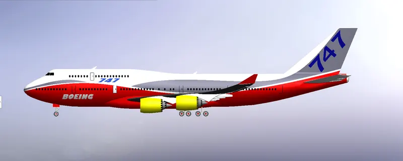
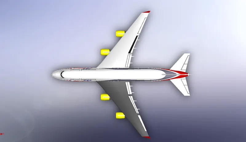
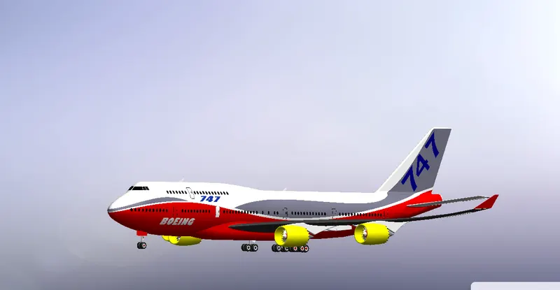
Appearance:
- To add an appearance, select the desired appearance in the appearance tab of the Task Manager.
- Left drag onto the model and hover over what you would like to apply the appearance to.
- Select Face, Feature, Body, Part or Assembly from the selection bar.
- Yacht model am using all painted materials.
Livery
- A livery is an identifying design, such as a uniform, ornament, symbol or insignia that designates ownership or affiliation, often found on an individual or vehicle.
- Livery will often have elements of the heraldry relating to the individual or corporate body feature in the livery.
Front view boeing-747
Side view boeing-747
Isometric view boeing-747
Photo view 360:
- Photo View 360 allows you to create a rendering within the SOLIDWORKS window.
- When you mouse-click Render Tools and Display Manager, you will see options to create a scene, add and adjust lighting, and also the option to add a camera if you like.
- For directional, point, and spot lights, you can set Shadow quality on the Photo View tab of each light's Property Manager.
- Higher values increase render times.
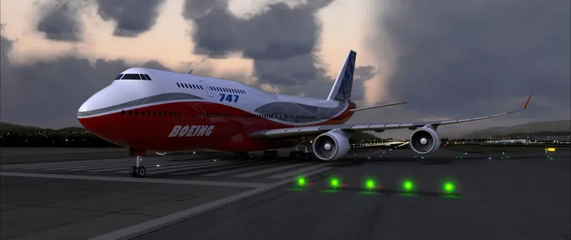
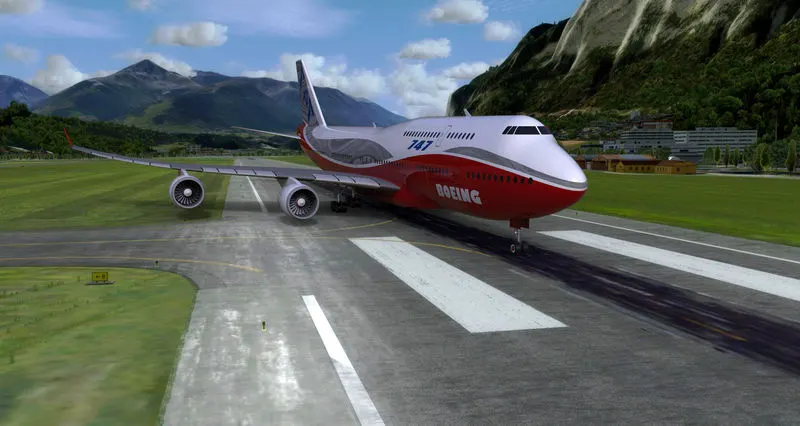
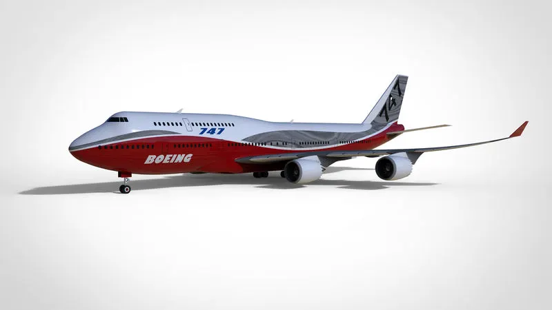
PHOTO REALISTICS RENDERING
pic 1
pic 2
pic 3
CONCLUSION
In this boeing-747 model I am using various type of 2d sketch ,3d feature, assembly tool, appearances, livery, various views and photo real look chopper model.
Boeing-747 all the parts and assembly files are upload here
https://drive.google.com/file/d/1y6oSogpBrkh_em77AX5x4XXGIeX5OKht/view?usp=sharing