Week 11 Challenge
- Create one assembly drawing considering all factors
Assembly drawing is a presentation of a structure or product with its components connected together, in their relative working positions while in use. These components are fabricated separately, and are assembled or installed together at their utility sites such that each part fits and matches with the others.
A drawing that displays the parts of a machine or a machine unit assembled in their relative working positions is known as an assembly drawing. An assembly drawing should be such that it should satisfy: (1) Manufacturing requirements (2) Operational requirements (3) Maintenance requirements.
Assembly drawings are classified according to their use.
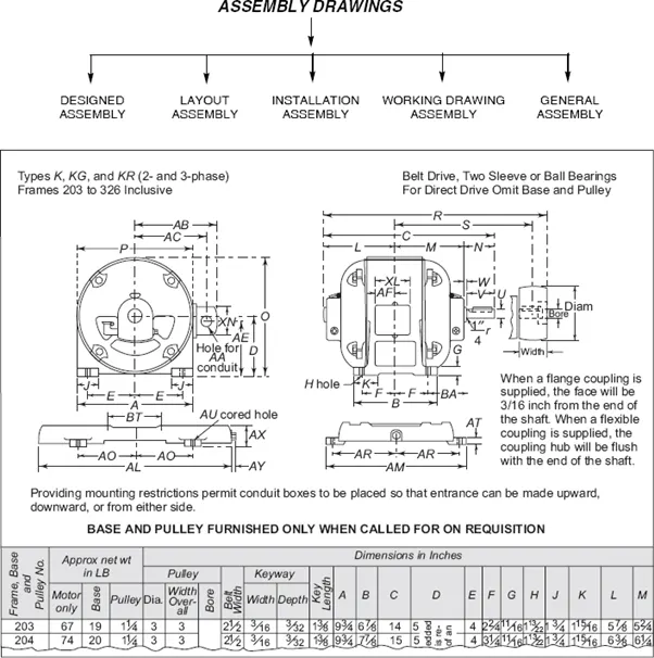
Here we are going discuss about the Tail lamp assembly design, the followings are the factors considered to making drawing,
Packaging distance:
The casing dimension of the lens as shown below, the tolerance value is given by (+0.1 / - 0.1).
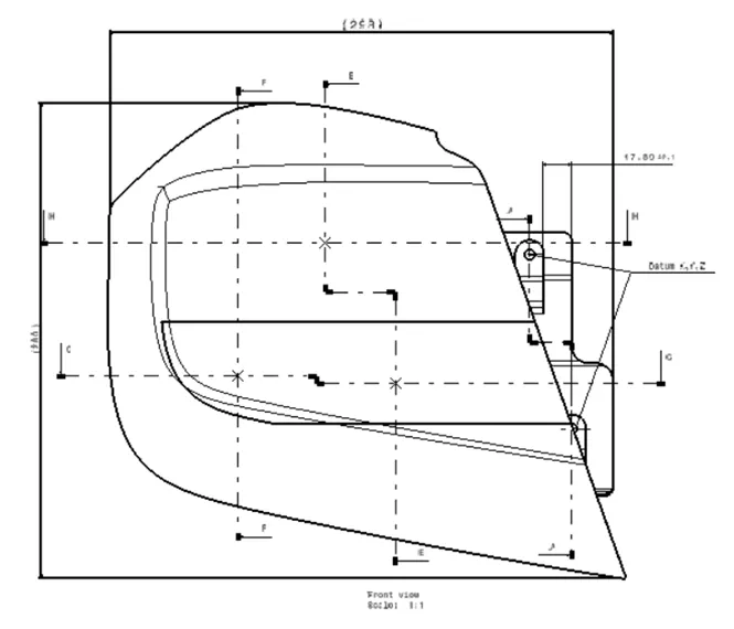
Front View of the lens
The section view is to give detailed information about the parts in the housing like screw boss housing, Dog House and M4 screw parts as shown bleow.
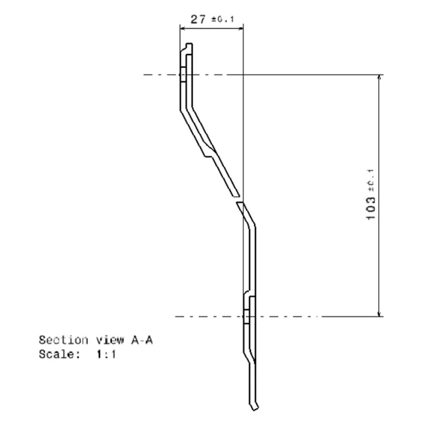
Section View of the BIW part
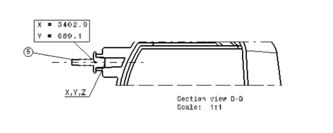
Section view of Screw Boss
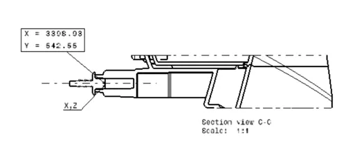
Section of Dog House
The right side view of the lens housing shows the calendar marking details and Marking as shown below.
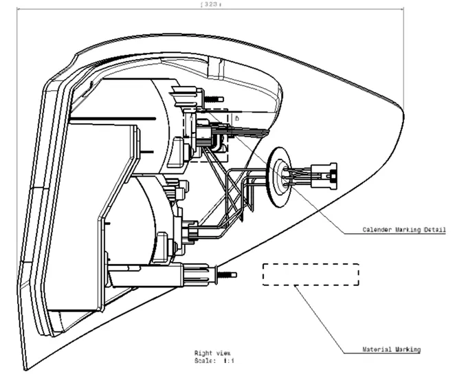
Side View of Lens Housing
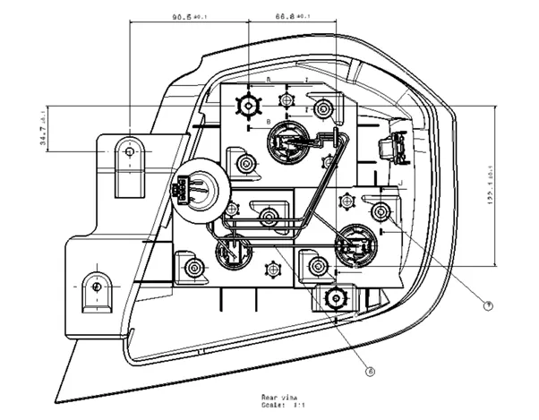
Rear view of Tail lamp Assembly
To highlight the features in the lens housing are viewed by the intersection section view as shown below, here all the factors are considered and important information’s are displayed.
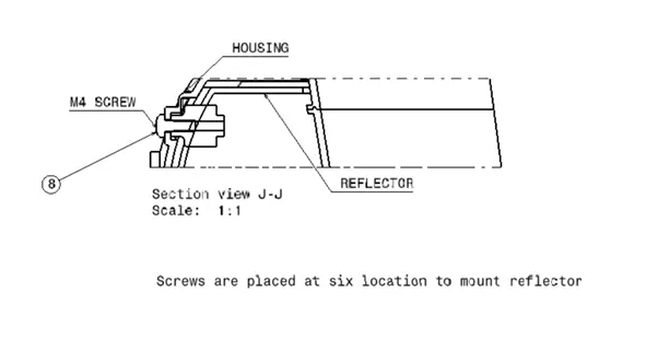
Section View to high light the M4 screw in the Reflector Housing
Tail/Stop Function Reflector:
Here for parting line the tolerance value is +0.7/-0.7 and the metalizing area is displayed in the diagram as shown below in the figure.
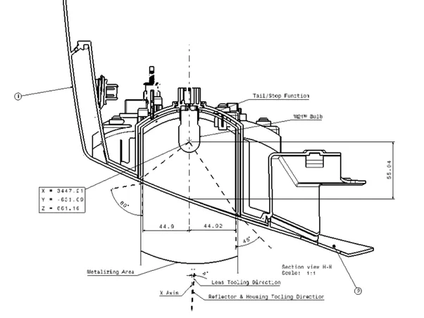
Horizontal section view of the Tail/Stop Function Reflector
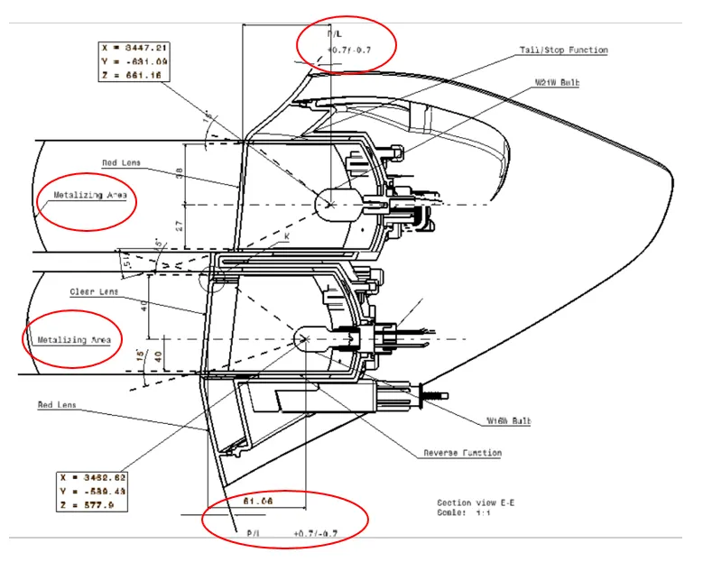
Vertical Section of Tail\Stop Function and Reverse Function
Turn Function Reflector:
Here for parting line the tolerance value is +0.7/-0.7 and the metalizing area is displayed in the diagram as shown below in the figure.
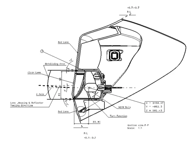
Vertical Section of the Turn Function
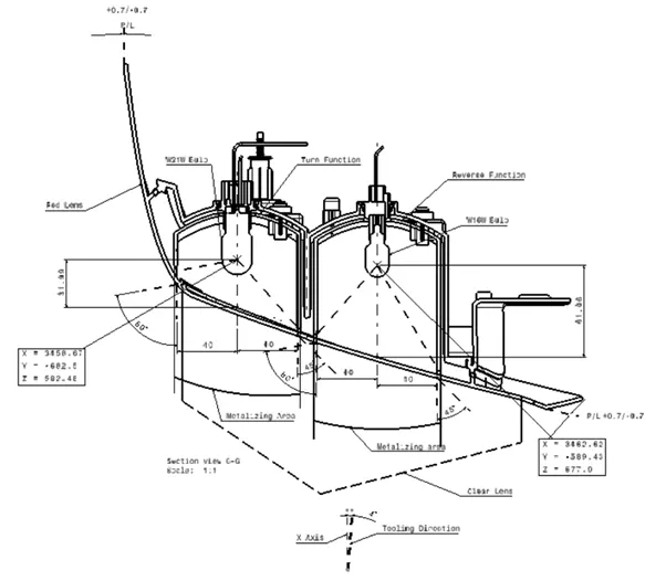
Horizontal Section of Turn Function and Reverse Function
The detailed view shows the insert molding of red lens and clear lens and the gap between the lens and housing.
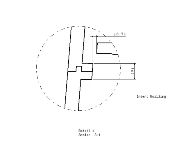
Detailed View of the Insert Moulding
The Detailed View of L represents the hot plate welding of lens and housing joining is welded as shown below,
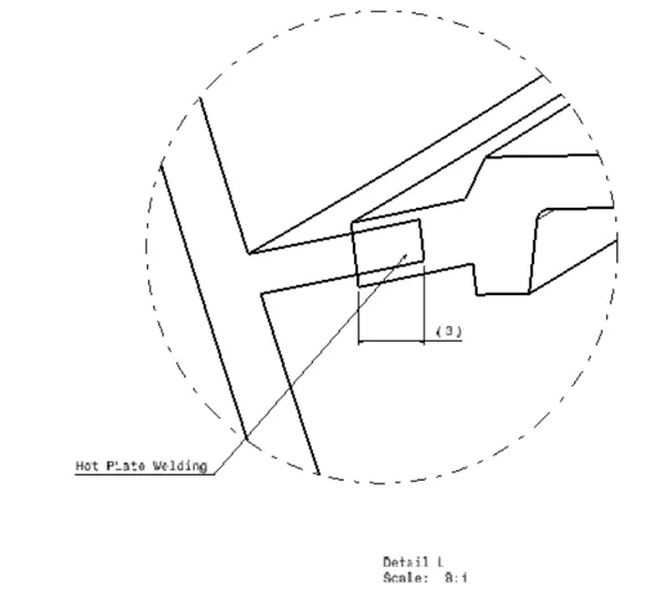
Detailed view of Hot Plate Welding
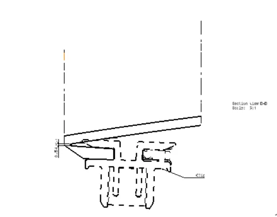
Intersection view of the Clip
BOM:
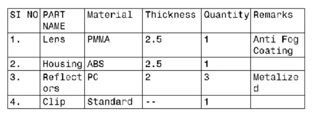
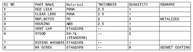
A bill of materials or product structure is a list of the raw materials, sub-assemblies, intermediate assemblies, sub-components, parts, and the quantities of each needed to manufacture an end product. A BOM may be used for communication between manufacturing partners or confined to a single manufacturing plant.
Here the BOM display list of parts in the tail lamp design:
- Make child parts drawing for housing and all three reflectors with notes
It refers to one lower-level item of an item in the structure. In the item structure where a product is a parent item, a component which is a direct constituent of the product is a child item for a product item. As depicted in the figure, the child items of Item Z are X and b, and the child items of Item X are a and b. In addition, Item X, a, b, or "イ" may be regarded as the child item of Item Z. Looking from a parent item, the lower-level items of its child item can be called grandchild items. For example, Item a and b are the grandchild items of Product Z.
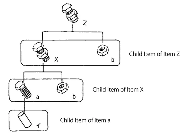
Child Part assembly
An item that appears in the BOM of another item is said to be a child of that item. For example, a motor would be a child item in the lawn mower BOM.
Here we are going discuss about the Tail lamp Child Part drafting for Lens, Housing, Reflectors and Clip the followings are the factors considered to making drawing,
- Lens:
The dimension and section view of lens is to give detailed information about the height and length of it and the clearly showed the red and clear lens in the below figure.
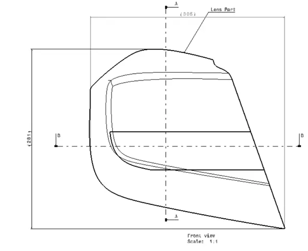
Front View of Lens Part
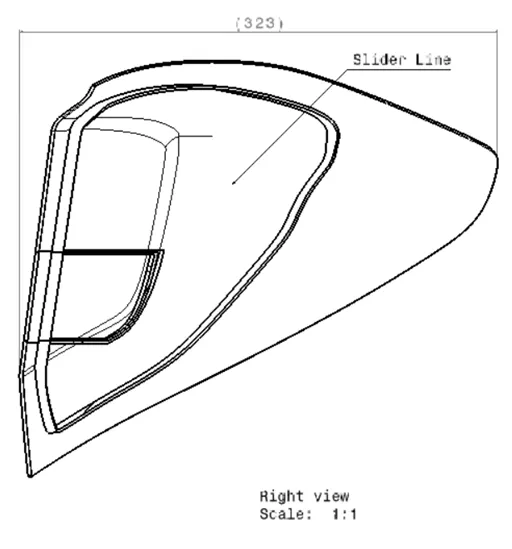
Side View of Lens
Let’s see the section of view of A-A which gives lot of detailed information about the thickness, Tooling direction, Anti Fog Coating area and tolerance value of (+0.1 /-0.1)
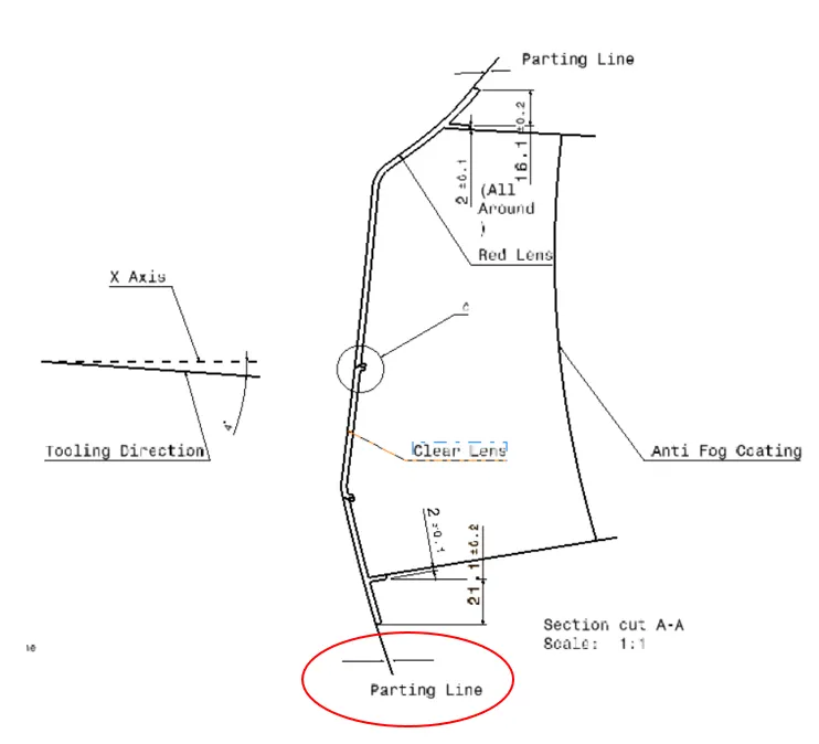
Vertical sectional view of lens
Detailed view C represents the dimension value of the insert molding properties of the lens.
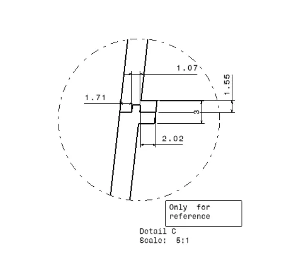
Detailed View of Insert Molding
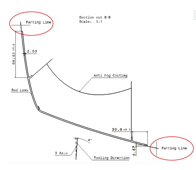
Horizontal Sectional View of Lens
- Housing:
The dimension and section view of lens is to give detailed information about the height and length of it and the clearly showed the red and clear lens in the below figure.
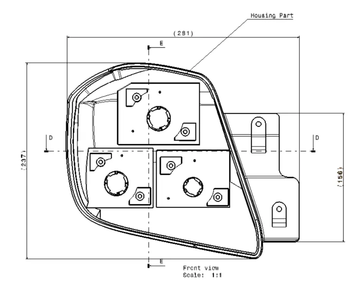
Front View of Lens Housing
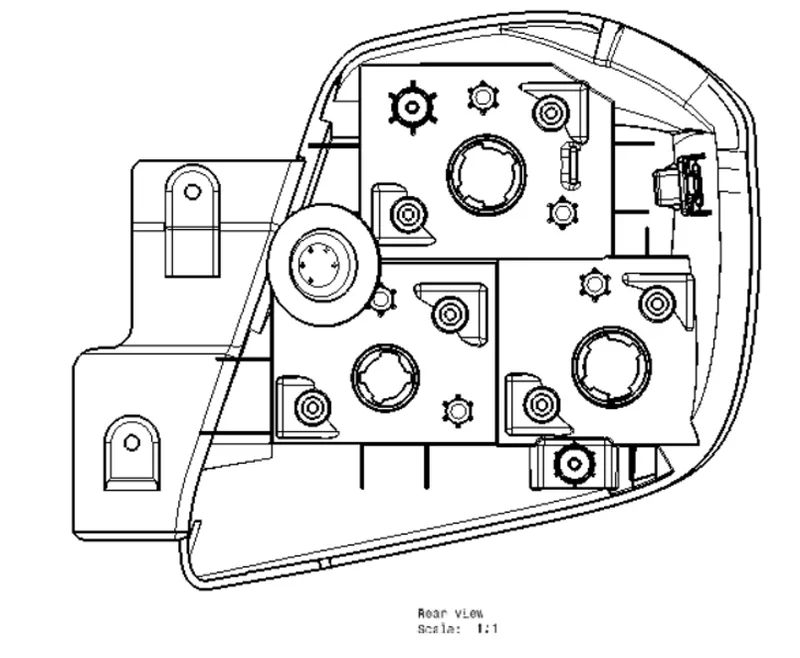
Rear View of Lens Housing
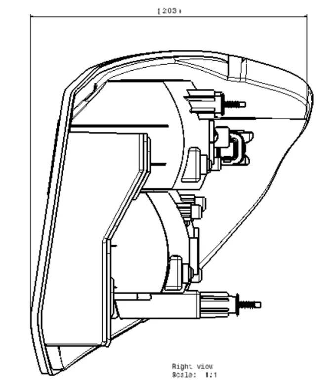
Side View of Lens Housing
The section view of D and E represents the vertical and Horizontal View of housing to have detailed look where the tooling and slider direction will come, and the thickness of the housing.
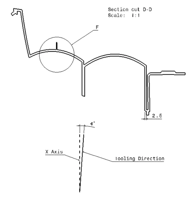
Horizontal View of Housing
The detailed view of F represents the vents hole in the reflector is shown below,
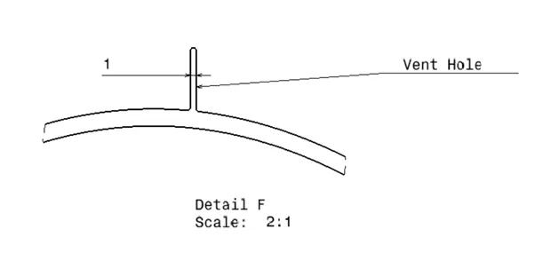
Detailed view of Vent hoe
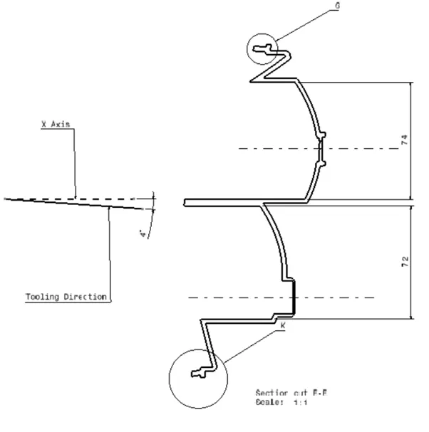
Vertical Sectional View of Housing
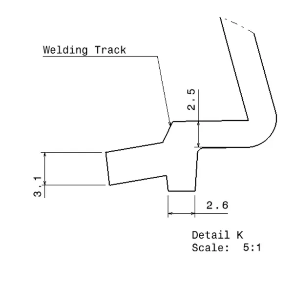
Detailed View of the welding track in the Housing
- Reflectors:
The dimension and section view of reflectors is to give detailed information about the height and length of it and the clearly showed the focal and positioned Point in the below figure.
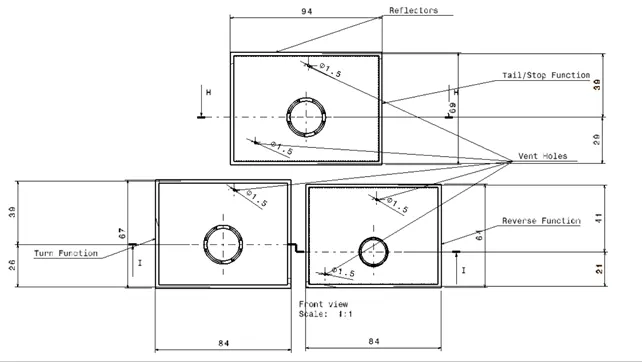
Front View of the Reflectors
The sectional view of H represents the tail\stop function reflector which shows us the wall thickness and area of reflector room.
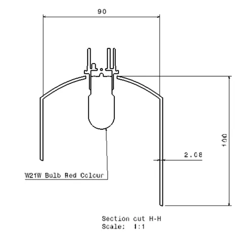
Sectional View of Tail\Stop Reflector
The sectional view of I represents the Turn and Reverse function reflector which shows us the wall thickness and area of reflector room.
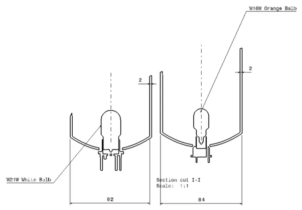
Sectional View of Turn and Reverse Function Reflector
The isometric view of the reflector shown the close up look of the flutes in the reflectors as shown below,
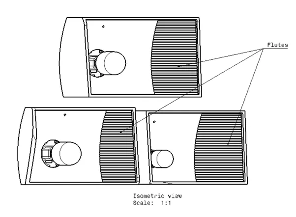
Flutes in the Reflector
- Clip
The dimension and section view of Clip is to give detailed information about the height and length of it and the clearly showed the placed in the housing wall below figure.
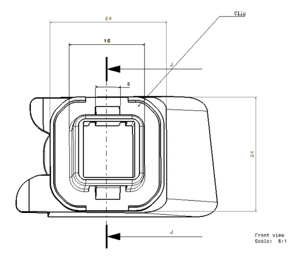
Front View of the Clip
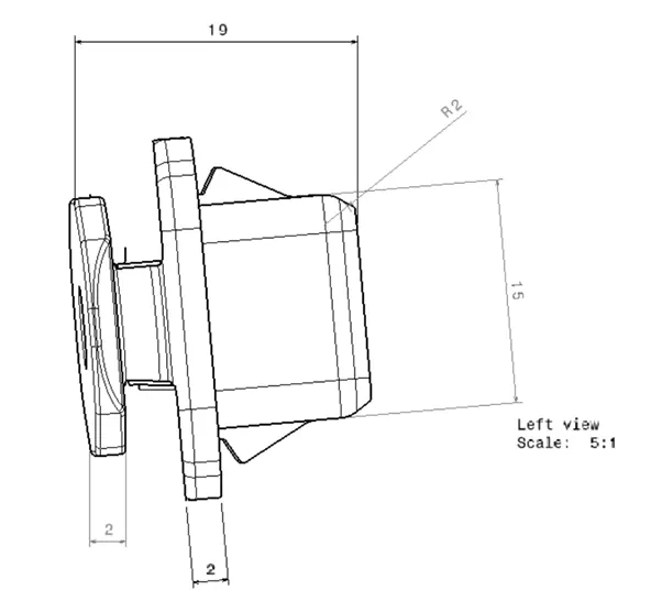
Side View of the Clip
The intersection view of the clip highlight information about the hollow and hole depth inside and the joining area to clip seating as shown detailed manner.
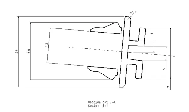
Sectional View of the Clip
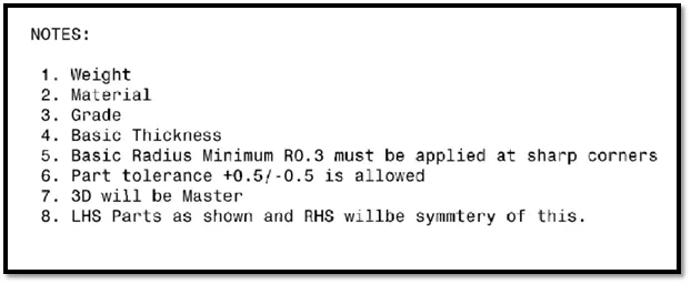
Notes for the Child Part Drawing:
BOM:
A bill of materials or product structure is a list of the raw materials, sub-assemblies, intermediate assemblies, sub-components, parts, and the quantities of each needed to manufacture an end product. A BOM may be used for communication between manufacturing partners or confined to a single manufacturing plant.
Here the BOM display list of Child parts in the tail lamp design: