Project 2
Aim:
- Initiate a rough concept of Fixture design with reference to all the inputs provided for the given Car panel.
- Complete 3D finish work.
- Complete 2D finish with Output documentation.
Introduction:
Body in White (B.I.W.) refers to the welded sheet metal components which form the vehicles structure to which the other components will be married, i.e., engine, chassis, exterior and interior trim.
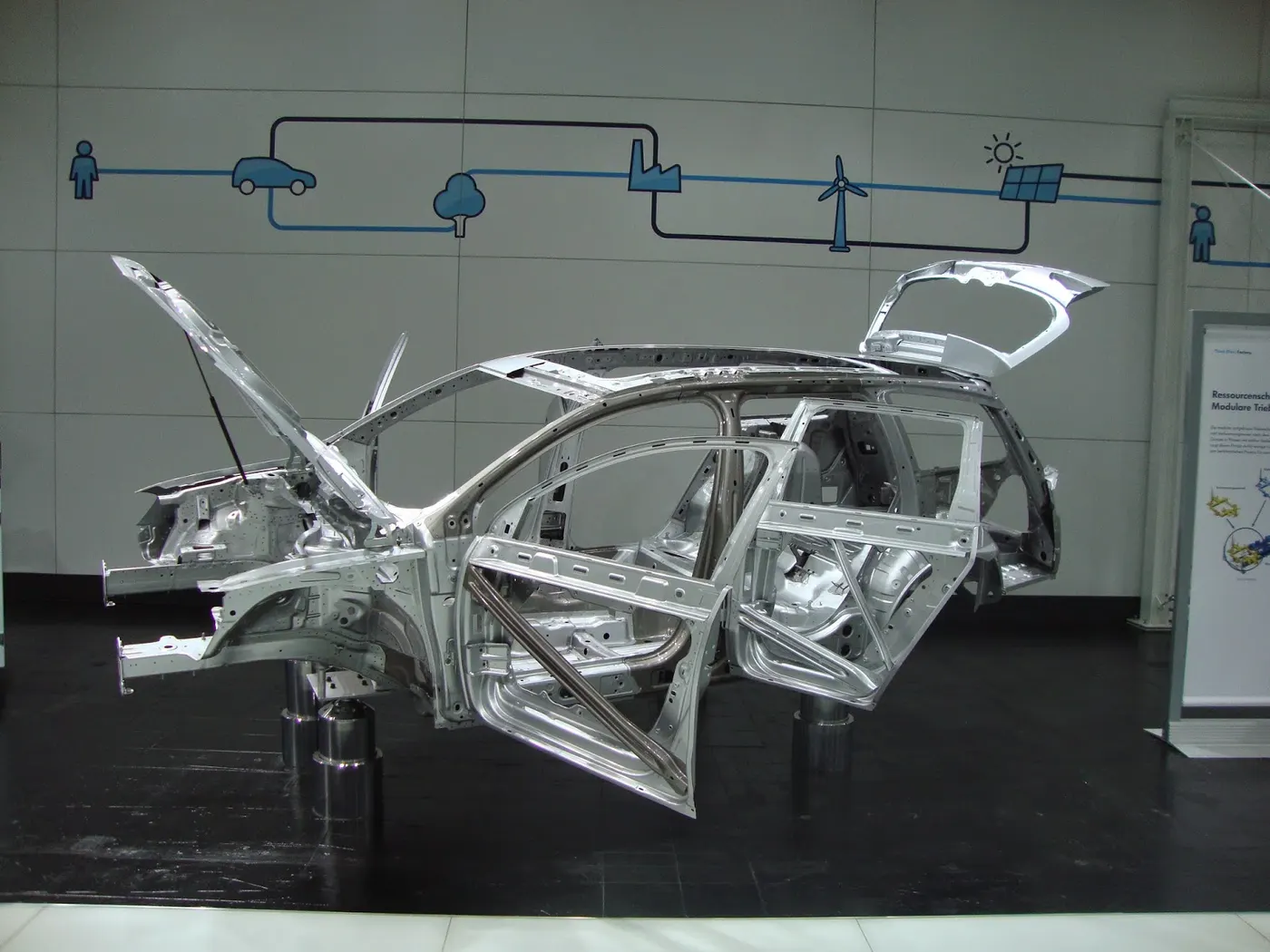
BIW refers to the stage in automotive design or automobile manufacturing in which the car body sheet metal (including doors, hoods, and side closers) has been assembled or designed but before the components (chassis, motor) and trim (seats, electronics items etc.) have been added. All activities in the production of a vehicle body before it goes to the paint shop are done in a body shop. The equipment used in the automotive industry has to meet the requirements related to the part’s weight and dimensions but also to the high production rates and high precision.
BIW Parts:
BIW parts are categorised as below
- Underbody structure
- Frond end structure
- Body side structure
- Closure
- Roof
BIW Fixture:
A device which is used to hold, locate and support the component in the manufacturing industry is called fixture. Fixtures ensure to provide the stability to the part when any process is being done on that part. That process can be welding, riveting, grinding, drilling etc.
In BIW fixture design Fixture works on 3-2-1 principle.
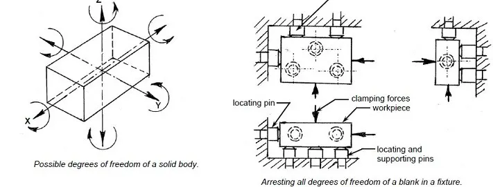
The 3-2-1 principle states that the six locators are sufficient to restrict the required degree of freedom of any workpiece. In this, motion is restricted using clamps and locators. A three-pin base can restrict five motions and six pins restrict nine motions.
[1] The workpiece is resting on three pins A, B, and C which are inserted in the base of the fixed body.
[2] The workpiece cannot rotate about the axes XX and YY and also cannot move downward.
[3] In this way, the five degrees of freedom 1,2,3,4 and 5 have been arrested.
[4] Two pins D and E are inserted in the fixed body, in a plane perpendicular to the plane containing pins A, B & C.
[5] Now the workpiece cannot rotate about the Z-axis and also it cannot move towards the left.
[6] Hence the addition of pins D and E restrict three more degrees of freedom, namely 6, 7, and 8.
[7] Another pin F in the second vertical face of the fixed body, arrests degree of freedom 9.
BIW fixture Terminology:
- Mylars:
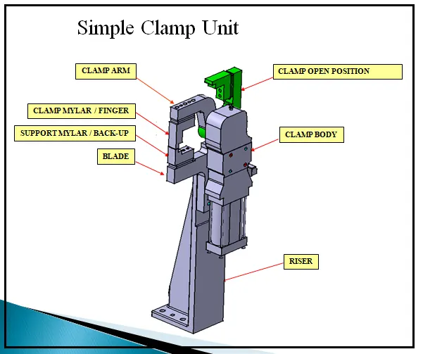
MYLAR is one kind of block that touches the panel and holds or clamps the panel. Mylars are always designed in CAR LINE. Mylar is also called NC(Numerically Controlled)Block. Mylars are mounted on any block or plate with Shimming, So that height of mylar can be adjusted accordingly at the assembly level. For ‘A’ class surfaces Nylon mylars are used. So that surface can be saved from scratches.
- Shim:
Shim is a set of thin plates (2 mm, 1mm, 0.5 mm, 0.25mm) that are used to adjust the gap or used for a better fit. Shimming can be of thickness 5mm, 8mm, or 10mm. in case no proper fitting between mylar and Panel due to manufacturing errors then this error can be removed using shims. Shims are placed in the carline position so that gap can be adjusted in the required direction like X, Y, or Z.
- Risers:
Risers are of different type like L-typer rises, Square tube riser etc. Riser is the manufacturing part which gives height to the assemblies.
- Blade:
Blades are plates mounted on the riser. Other parts like cylinder, arms etc are mounted on the blade.
- Rough locators:
The operator can place the part in wrong orientation mistakanely. The rough locator will work as a guide while placing the part in the fixture & the part will be loaded in desired orientation. It is a part of fool proofing.
The fixture is the assembly of different types of units to form a fixture. There are different units like pin unit, base unit, clamping unit etc.
- Number plates:
Number plate is the aluminium embossed plate placed on the each unit for easily recognising the unit.
- Name plate:
The data like manufacturing company name, fixture type, Fixture weight etc. is embossed on the plate & joined to the fixture.
- Clamp Arm:
Clamp arm is the part of clamp unit which moves over a axis. Over clamp arm the Mylars are mounted.
FIXED PIN
Fixed pin unit is a unit designed to locate the car panel using pins. Pin, pin retainer, shims, blocks, blade, riser are the part of fixed pin units in general . pin retainer is used to hold the pin firmly.
The fix pin and the retractable pin units are hole constraining fixtures for car panels.
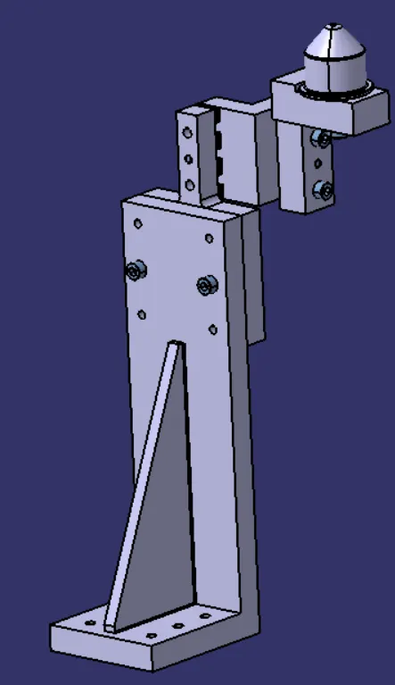
RETRACTABLE PIN UNIT:
- Retractable pin unit is opposite to fixed unit which can be moved up and down up to a certain distance.
- It is used for unloading complex panels after welding.
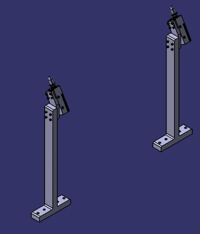
Procedure:
- The car panel for which the fixture is to be designed is imported into the project.
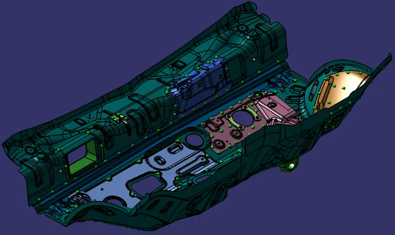
For designing any fixture 3-2-1 principle is the most important thing to be considered. Here also 3-2-1 principle is taken into consideration while designing. Different units are used to fullfill the requiremnt of constraining the DOF of different part like Fix pin units,retractable pin units, Power clamp units, Rest units etc.
- The Holes and slots are located and the pins are designed as per the diameter of the hole and it is made sure that the axis of the pin and the axis of the hole must be coincident. The pins designed may be Round or diamond-shaped.
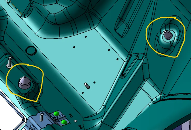
Simlutaneously the Pin units are designed with necessary dimension and also provided with various threaded, dowel holes as required.
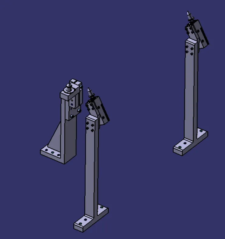
Next step is to create / design the clamp units.
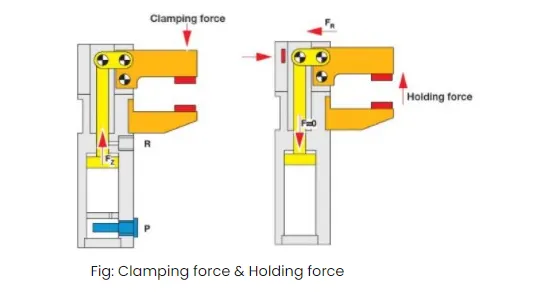
FORCE ACTING IN CLAMP & REST UNIT:
TO design a clamp unit we have considered some force that acts in the clamp for clamping purpose the force that act in clamp units are,
- Clamping force
- Holding force
Clamping force is not the same as holding force.
CLAMPING FORCE:
clamping force signifies the force applied to the workpiece by the drive mechanism via the clamp arm during the gripping or clamping operation.
Clamping force (Fs)= 48xS3 = force in newton HOLDING force
HOLDING FORCE:
holding force on the other hand denotes the maximum force, after locking the knee lever (over-center position) that can be applied by the workpiece on the workpiece on the gripper/ clamp arm without destroying the mechanism therefore particular attention the paid to the maximum holding force when for example during the production process (welding, bonding)there is a possibility of distortion of the component or if the clamp arm is used as a fixed stop.
If the holding force specified in the technical details is exceeded this will inevitably result in the destruction of the mechanism the clamp arm of the bearing position.
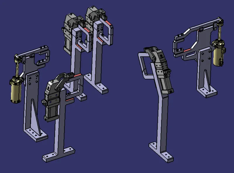
Power clamp unit is the unit designed to hold the car panel on the position to do some process over the part. It includes NC block/ Rest/ Mylar by using pneumatic clamp cylinder. The power clamping devices are utilized for positioning and holding product securely. It applies pressure on the product to hold it on the specified position. The holding should be firm enough to hold part on its position & also it should not damage the part as well.
The mylar are modified according to the shape of the car panel.
Two rest unit are designed further to give more support for holding the panel in position as shown below.
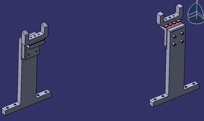
Now since all the required pin unit, rest unit and the clamp units are designed using 3-2-1 principle of retriction of movement of the panel. Next step is to design the Base unit for the Fixtures to rest on.
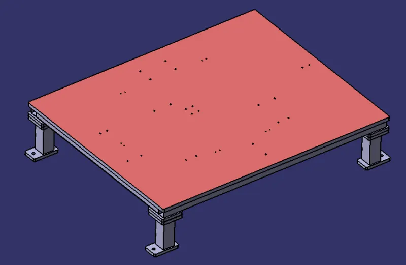
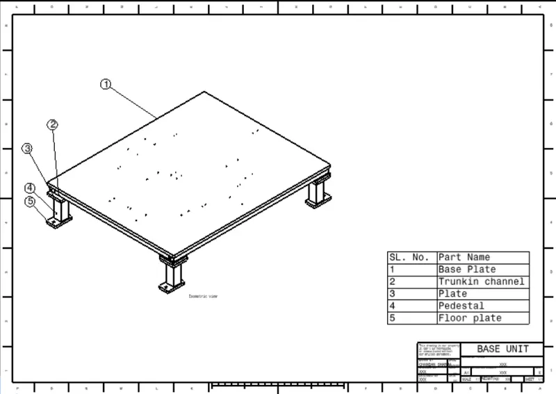
Base unit is a unit which is used to mount all the units such as clamp unit, pin unit, rest unit etc., of a tool and also other necessary table parts like pneumatic valve box, trunkin cable path.
Base plate:
The base plate is machined plate of 25 to 40 mm thickness made of steel & aluminum, on to which the holes are drilled to mount the individual units like clamp units, pin etc., of a tool.
Pedestal:
A pedestal is a part which connects the base plate to floor plate. A pedestal is a standard part in general & in some cases it can be a welded frame integrated with the base plate.
- A standard pedestal can be of different height & different sizes.
- Depends on the size of the base plate, the number of pedestal varies for load distribution.
- A pedestal is of different types with different inclinations.
Trunking Channel:
A trunking channel is duct which accommodates all the pneumatic & electrical hoses and wires for the units of the tool. It has thickness of few millimeters.
Floor plate: Floor plate is grouted to the floor with fixed bolt on the ground. Floor plates are also called as foundation plates
- There will be a clearance of 10 mm maintained between the pedestal base plate & floor plate.
- This clearance will be used by the leveling screws, for leveling the entire tool.
- Weld bars are be used to weld the positions permanently after leveling is done.
- A weld bar is a plate along the sides of the base plate of the pedestal.
The points need to be taken into account while designing the base unit are:
Working Height:
- It depends on the nature of the manual or robotic welding fixture.
- For manual fixtures working height of 850-1100 mm is needed to be considered, depending upon the working height of the worker standard of a specific country will apply (In a few countries human height is higher or lower e.g. US, Japan).
- If the base structure is made with a base plate having a tubular structure welded below it then we can reach to height of 100 mm to ~250 mm. In this case to reach the working welding height we need to provide additional some leg structure which may have the top and plate welded to the tube.
- Try to study the gun ergonomics properly then design the unit height and then base top height.
Base Plate or Welded Structure:
- Depending upon the component size and weight of the total units we can decide whether we need a fabricated base or just a plate.
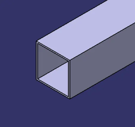
- Mostly fabricated bases are used made of square or rectangular tubes with plates.
Selection of Eye Bolt:
- As a designer, it is important to know how a big base plate or bigger base welded structure will be handled during the fabrication and handling process.
- Depending upon the weight eye bolt size is selected for lifting holes on the base plate.
- Generally, 4 eye bolt provision is made. We also need to select the location of the eye bolt considering the rope/ belts used while shifting the structure or complete fixture are not damaging any units (rest, clamp, or location units) nearby.
Number of Measuring Holes Required:
- We would need 3 holes to define the plane.
- If the base length is too long few OEMs follow the methodology of having dowel holes at a 500mm distance.
- Most of the OEM makes 4 dowel holes at 4 corners and put small aluminum plate marking X,Y &Z coordinates of dowel holes. If the base length is too long few OEM's follow the methodology of having dowel holes at 500mm distance.
- The base unit of the fixture must be strong enough so that deflection of the fixture is as minimum as possible. This deflection of a fixture is caused due to the forces of welding, clamping of the workpiece.
- The base unit of the fixture should have the mass to prevent vibration & chatter.
- The base unit may be built from a simple section so that other unis are fastened with screws or welded necessarily.
- Those parts of the fixture that remain permanently with the fixture may be welded. Those parts that need frequent changing may be held with screws.
- The base unit should be parallel to the floor, to adjust it there should be the provision of the height adjusting mechanism.
Fundamentals of Base unit:
- A base plate size should cover all the units with its outer periphery including the opening.
- A base plate is always preferred to be designed with respect to BCS Coordinates.
- A base plate should be drilled with datum holes/ measuring holes in line with a pitch of 1000 m in general.
- The number of datum holes depend on the size of the base plate.
- Datum holes should be drilled at nominal values of co-ordinates and in terms of 50 and 100. Example, X=100, Y=-600, Z=250.
- Datum holes should be covered with cover plates.
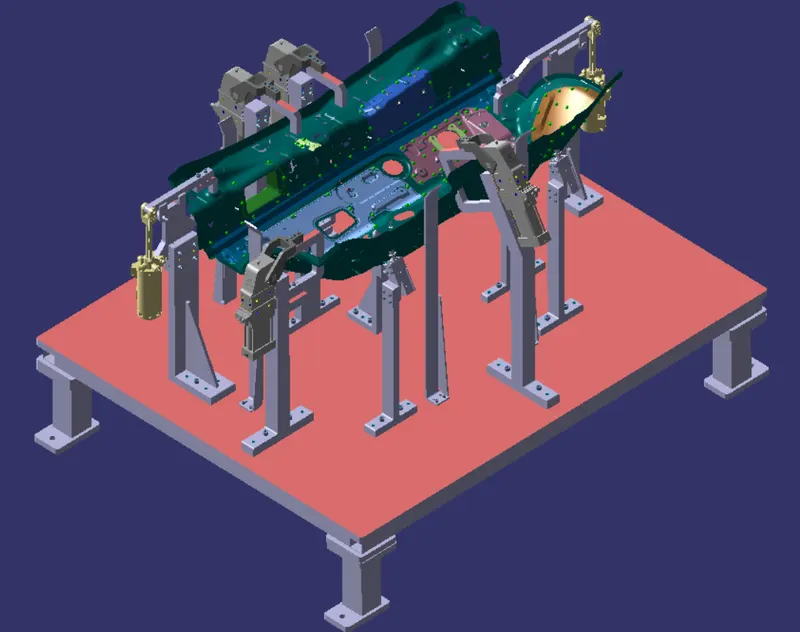
Now all the parts are assembly together as shown in below image:
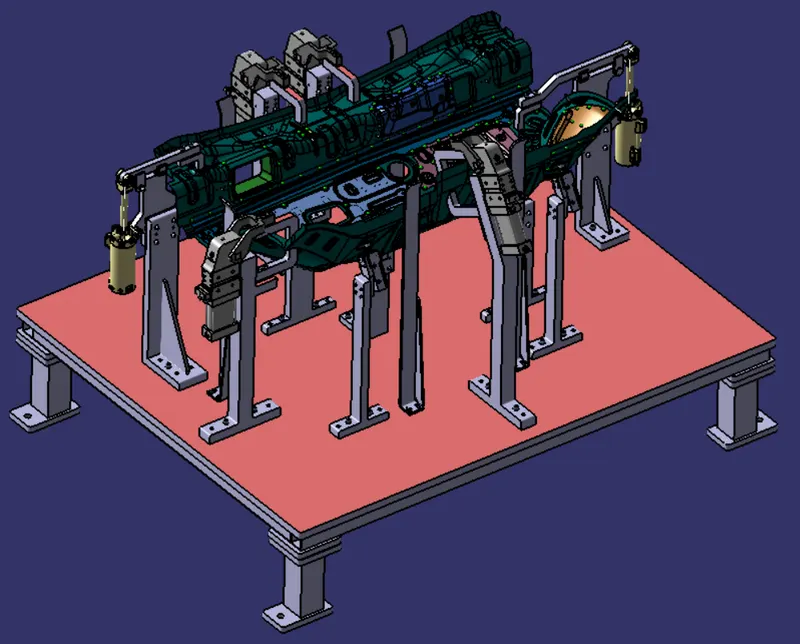
3D Finish:
3D finish is process where the design is being completely finish and to be ready for final simulation and 2D detailing.
Points need to be taken care of while finishing the design?
- Hole concentricity and hole sizes: All parts Hole concentricity should be checked & confirmed for easy assembly while finishing the parts.
- Machining area.
- Nominality : All units dimensions shoild be maintained nominal to facilitate easy assembly of the unit.
- Holes coloring standard : The holes should be coloured according to the standards with different colour for different hole sizes.
- Pneumatic lay-outing : Proper layouting of the pneumatic or cables.
- Gap cheching : To check if there any clash or gaps between the 2 assembled parts.
- Fastener implementation: Fasteners should be implimented in all unit as per the requirement & load on the part. like bolts, washers, screws etc.
- Avoid clash between different parts: Proper gap should be maintained between parts to avoid the clash.
- Mylars splitting as per panel pofile: Mylar splitting should be confirmed while finishing the design (It shuld be split with reference to the panel).
- Proper renaming of parts and assemblies as per the standard.
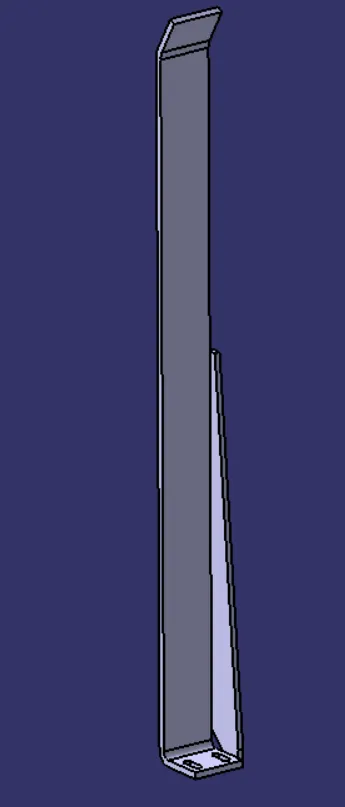
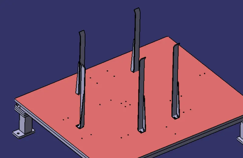
Rough locators are elements that aid the operator to guide / locating the car panels while loading onto the fixture and ensure a fool-proof assembly. Locating refers to the desired location where you want the workpiece to be when it is getting worked on either by a person, team, or robot.
Material used uded for rough locators are MS or similar metal.
Rough locators are desingned at appropriate locations as shown below:
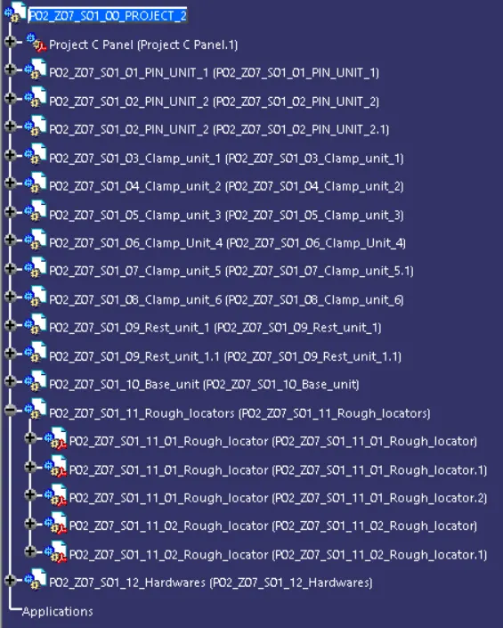
The first step in the finishing process of the design is renaming / structuring the family tree comopenents in series as shown in below images:
Checking the nominality of the Holes on the Base plate:
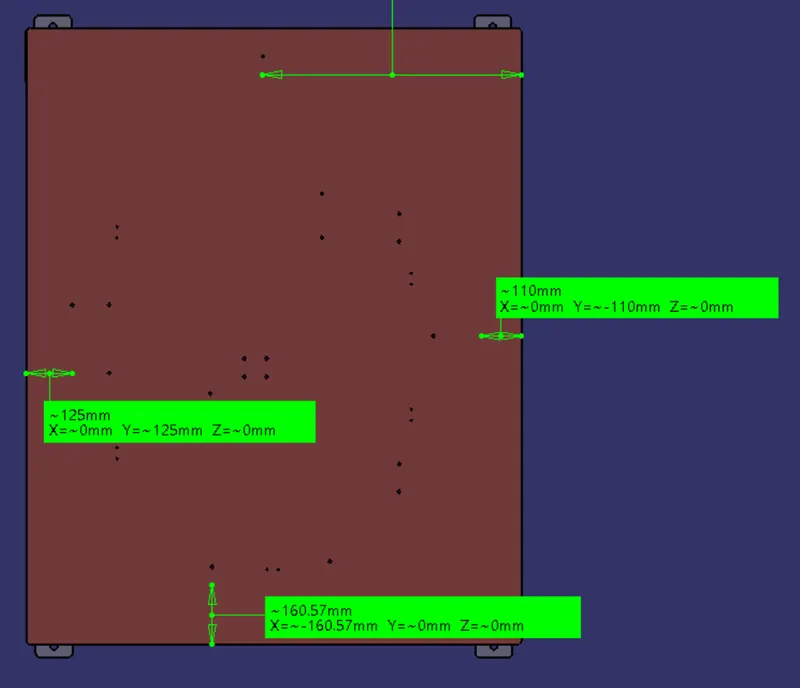
In the above image the base plate surface colour is changed desribing the machining surface.
Hole colouring standard:
The holes are assigned with a colour according to the uses as shown below:


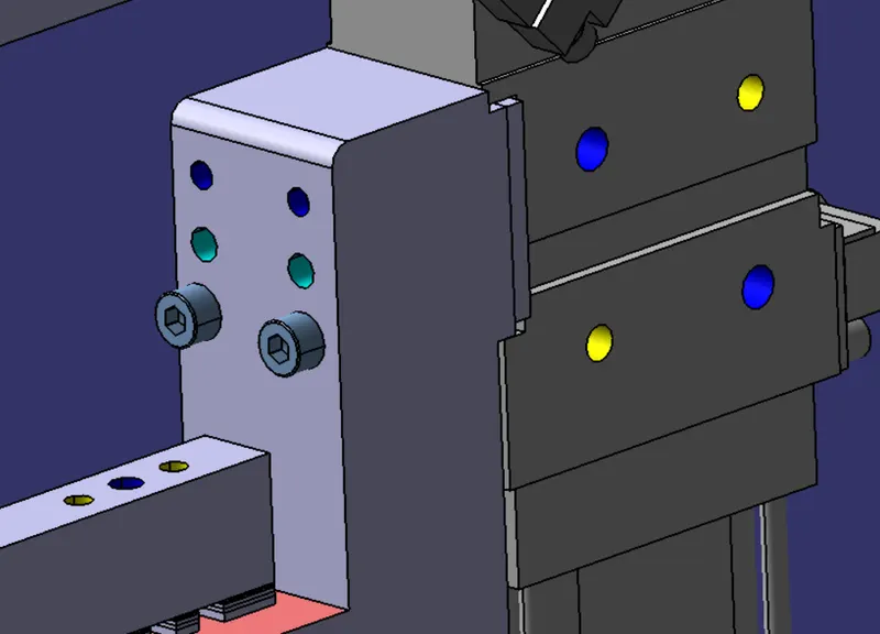
Dowel Hole: Blue Colour
Threaded Hole : Yellow colour
|
Checking Parameter |
Action |
|
Rename of the design tree |
Done |
|
Mark Machining Area |
Done |
|
Nominality |
Done |
|
Holes colouring standard |
Done |
2D Detailing:
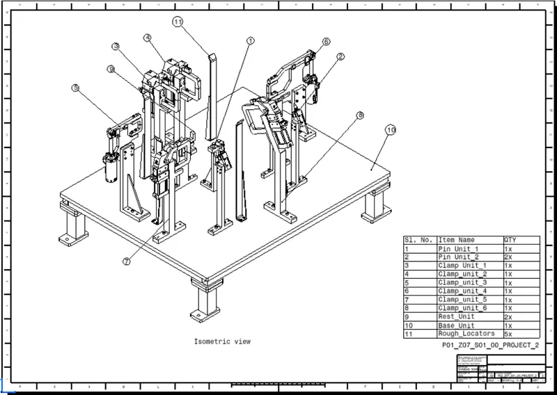
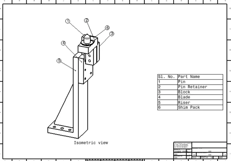
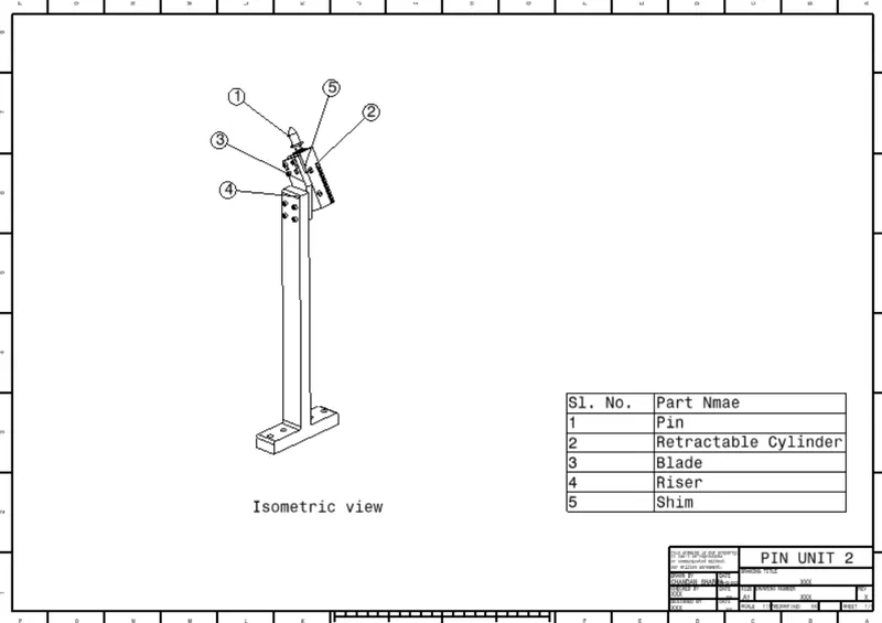
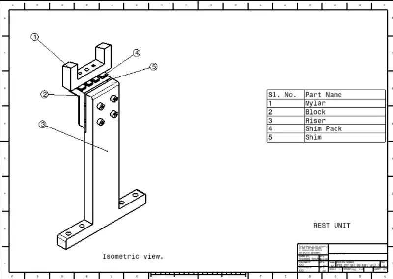
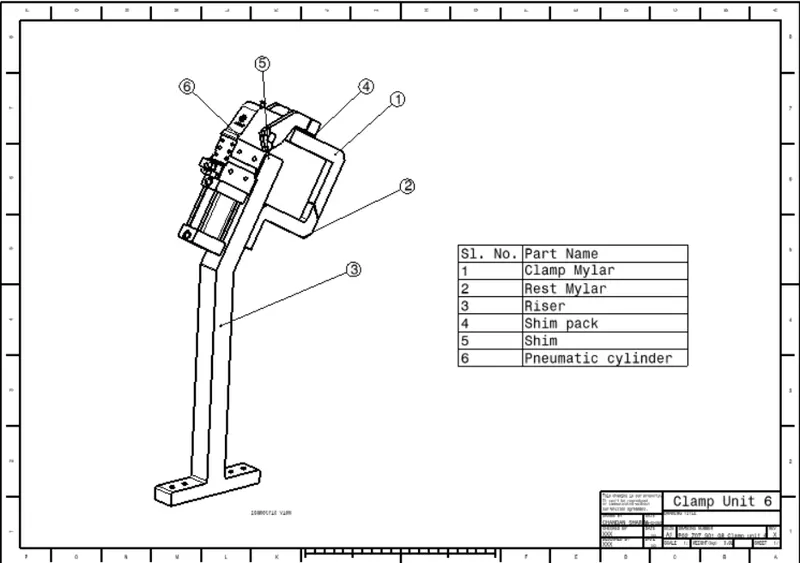
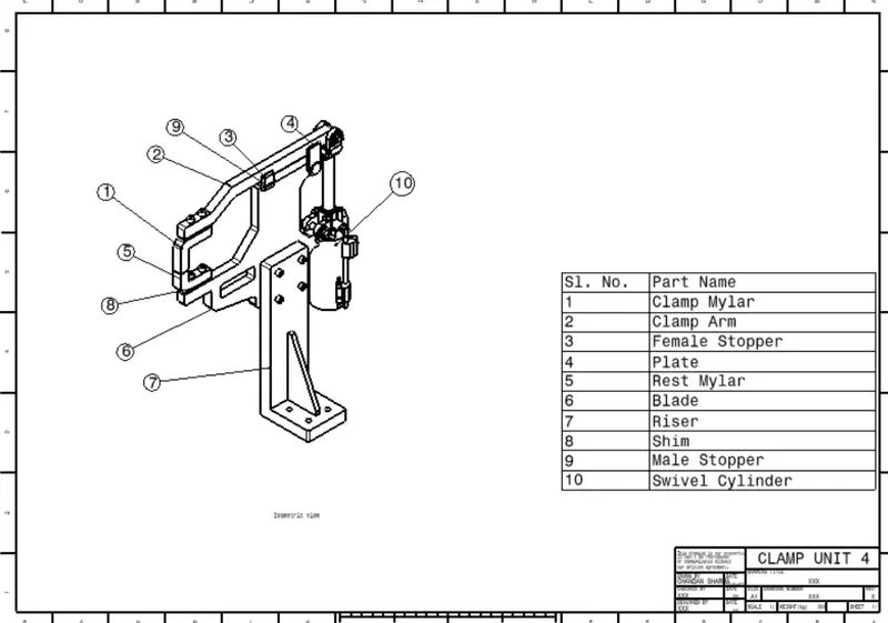
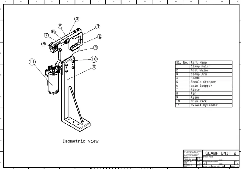
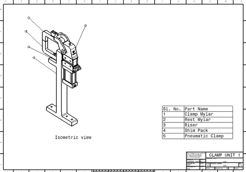
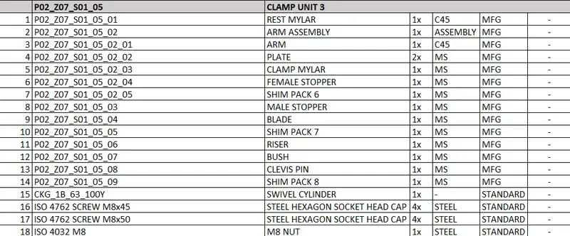
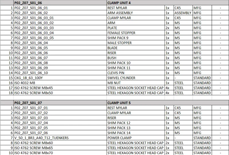
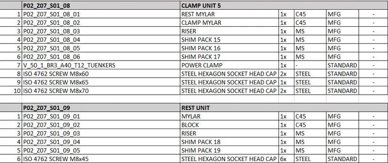
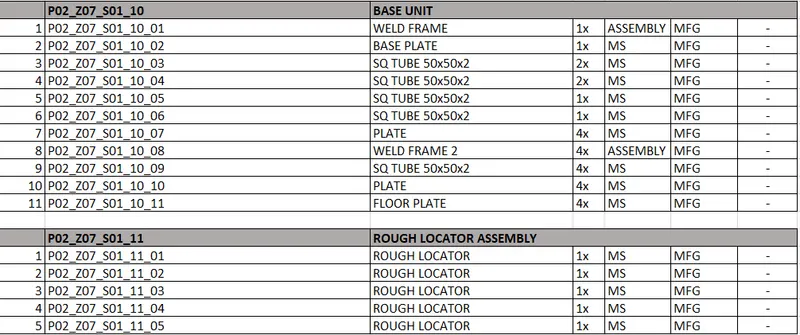
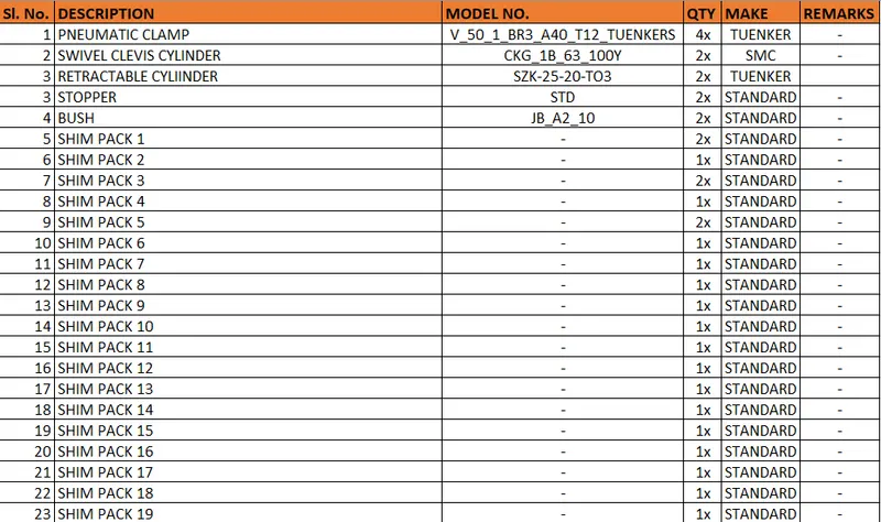
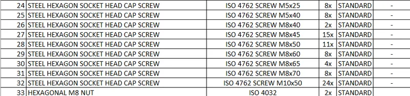
BOM AND BOP:
CONCLUSION:
- Various Fixtures like Fix pin unit, Clamp unit, Retractable pin unit, Rough locators and Base unit are designed.
- 3D Finish procedure is carried out on the assembly by considering standdard procedures.
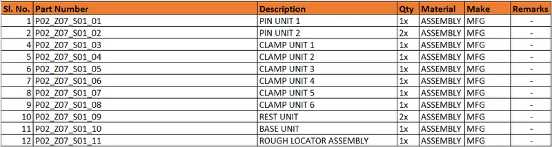
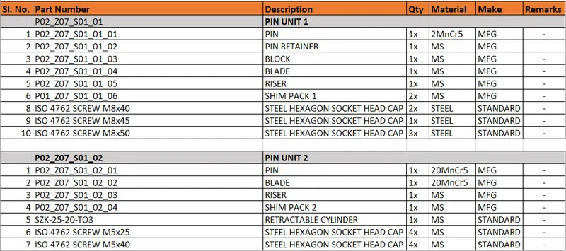
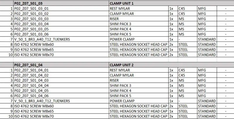
- 2D detailing is created with documentation like part list, BOM and BOP for thr complete fixture assembly.