Wiring harness design in CATIA V5 - 3D modeling Week 2 Challenge
WIRING HARNESS DESIGN IN CATIA V5 - 3D MODELING
AIM:
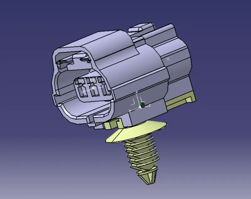
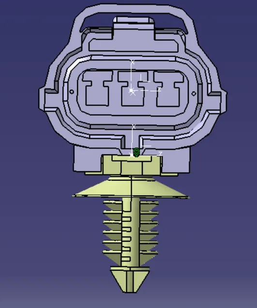
Download following connectors & Connector clip cad data from given link & define it as Electrical Connector using Electrical Part design Workbench. Define all the necessary properties to Connectors & Clip.
Deutsch DT06 – 08SA ( https://www.te.com/usa-en/product-DT06-08SA.html)
Tyco 174357-2 (https://www.te.com/usa-en/product-2-174357-2.html?source=header-match)
Tyco 85229-1 (https://www.te.com/usa-en/product-85229-1.html?q=85229&source=header
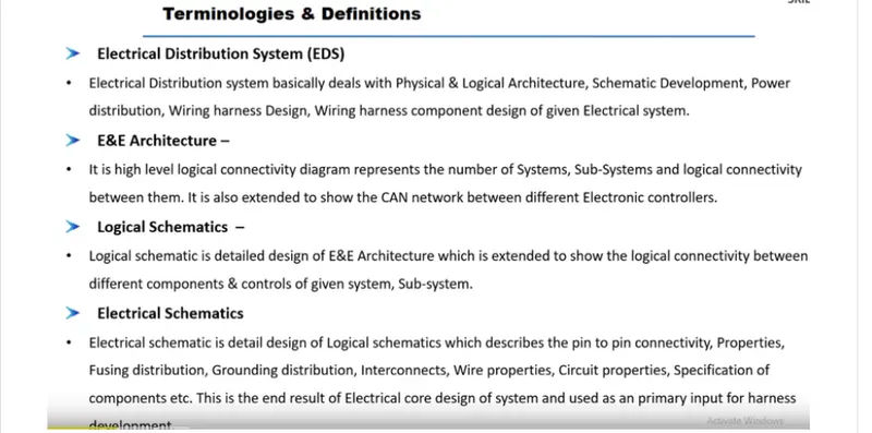
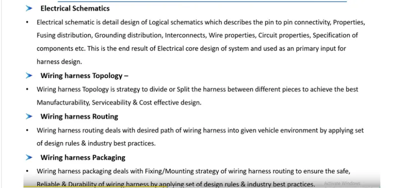
INTRODUCTION TO WIRE HARNESS
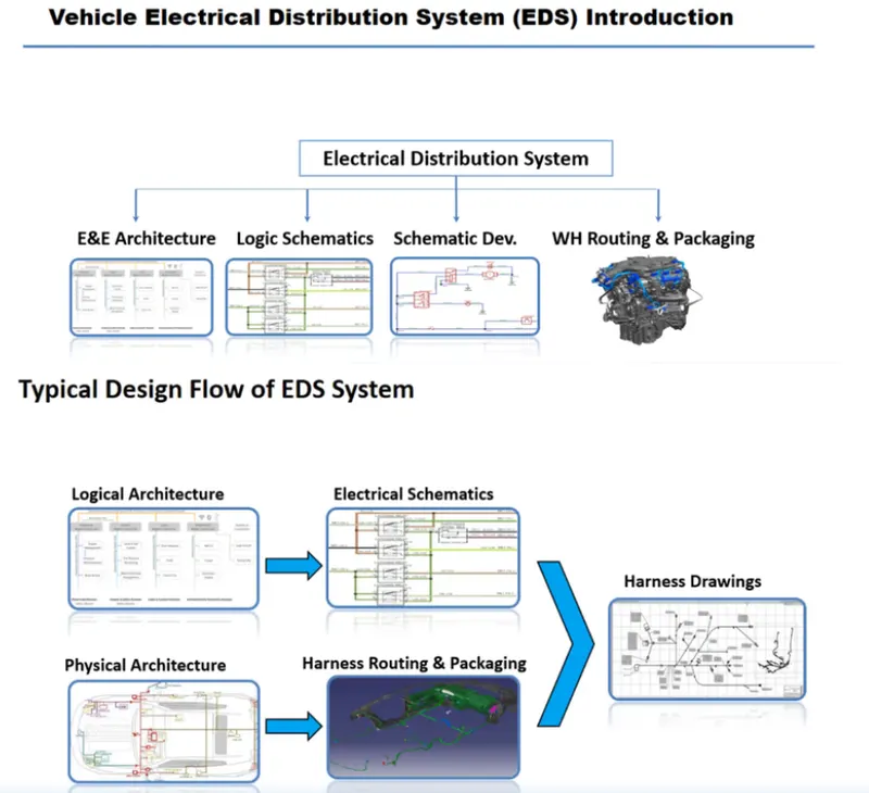
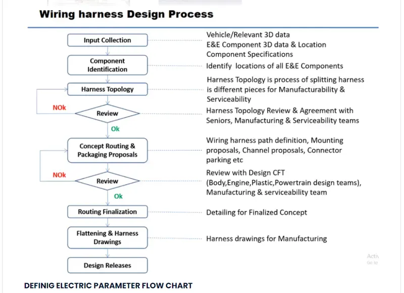
DEFINIG ELECTRIC PARAMETER FLOW CHART
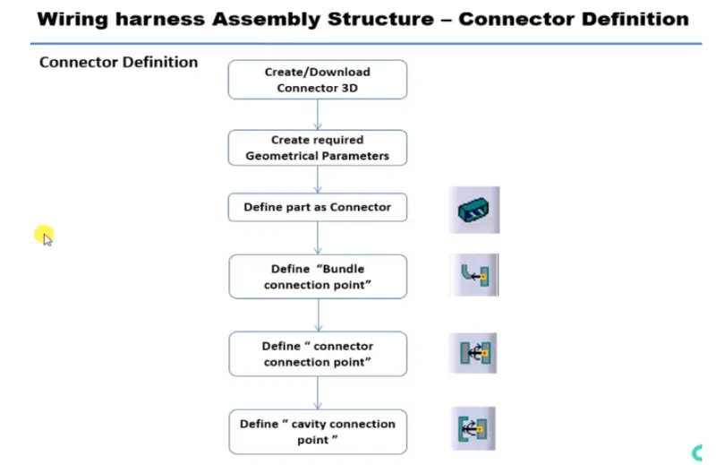
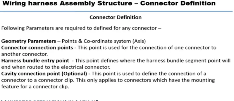
CONNECTOR DEFINATIONS IN CATIA V5
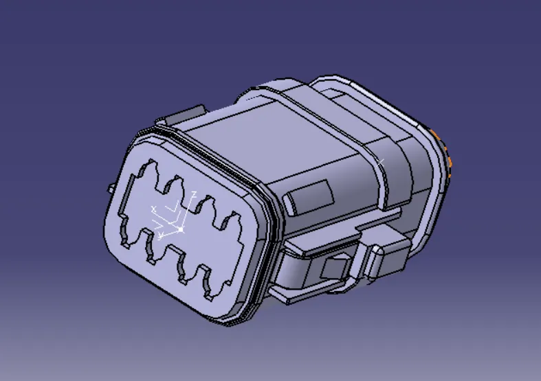
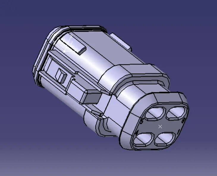
- Deutsch DT06 – 08SA
Connector connection point:
Bundle connection point:
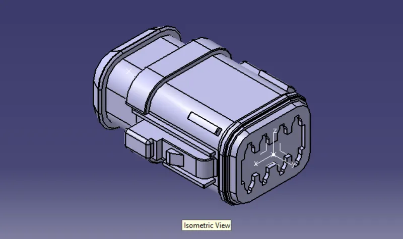
Switch to 'Electric Part Design'
Define the part as connector in catia, give no. of termination as 8 because we have 8 entry points for wire.
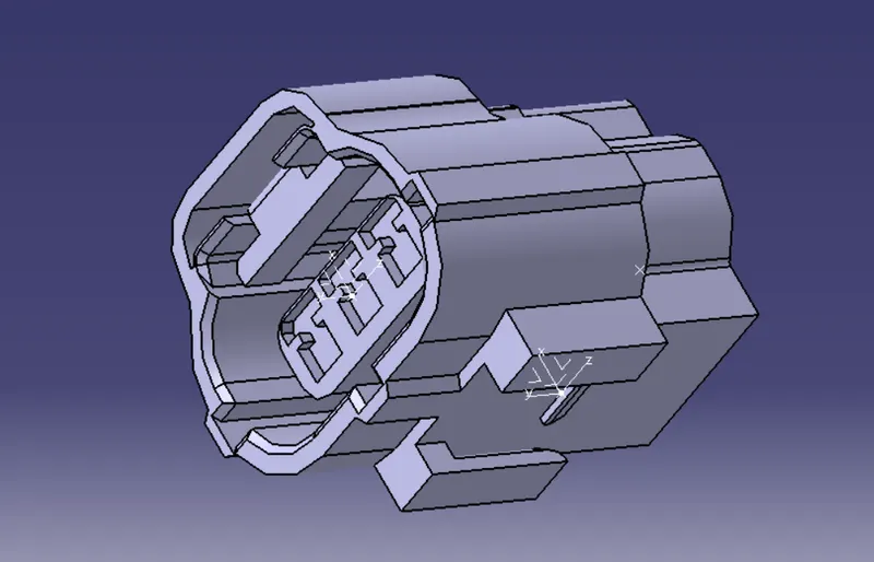
2.Tyco 174357-2 :
Create midpoint
create Connector connection point
create Connector connection axis system
create cavity connection point
create cavity connection axis system
Switch to Electric part design and define part as connector
Define Connector connection point and cavity connection point
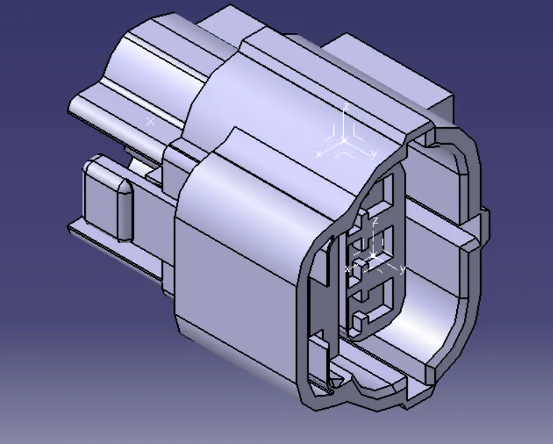
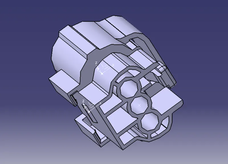
- Tyco 85229-1:
Create midpoint
create cavity connection point
create cavity connection axis system and orientation should be same as in connector
Switch to Electric part design and define part as Mounting Equipment
Define cavity connection point
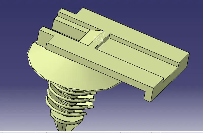
Elctric Assembly Design
Import Connector and cavity / mounting clip.
Select Defing Eelectric connection
select cavity and then connector.