Frontal crash test using Hypermesh and Radioss
Aim: To simulate the frontal crash test of a car's BIW structure using Hypermesh & Radioss for its crashworthy analysis.
Objectives:
- Check unit system and either follow[Mg mm s] or [Kg mm ms].
- Create appropriate interface ,friction 0.2 and recommended parameters.
- Make sure of no penetrations and intersection.
- Correct rigid bodies if any issues.
- Create rigid wall with friction 0.1.
- Compare the model weight with the full scale 300k nodes model and use added masses to reach target weight 700kg while getting CG about the required range.
- Initial velocity 35 mph.
- Use model checker to ensure good quality.
- Time-step :0.5 to 0.1 microseconds.
- Run 80 ms.
Output requests:
- Sectional force in the rails at location of indicated node 174247.
- Axial force received on the rails from bumper.
- Shotgun cross sectional forces.
- A pillar cross section.
- Acceleration curve received on the accelerometer at base of B pillar (on B pillar rocker).
- Intrusions on the dash wall 66695,66244.
Introduction:
This project aims at understanding the flow of forces in a cars BIW structure during a frontal crash and how these forces reach toward the passengers. The parts such as the axial rail, shotgun, A pillar etc contribute more to the transmission and also absorption of this force. As per the amount of force transfered we can analyse the crashworthiness of the structure.
Whenever a front cash happens, the impact force is proportional to the kinetic energy of the impact. This kinetic energy referes to the speed of the vehicle(0.5*m*v^2). Higher the kinetic energy, higher the impact force. This impact force should be damped on its way towards the passengers. Damping will happen when the parts which are transfering this force will absorb it. Absorbing of the force is nothing but increasing the internal energy of these parts by deforming.
The ability of the parts to crush and reduce the transfer of force is the magic formula to determine its crashworthiness.
Case setup:
The preprocesser used is Hypermesh and solver is Radioss.
Firstly the BIW structure starter file (0000.rad) is imported in Hypermesh, checked for initial penetrations and intersections, check for weight of the model to be 700kg or not, position of CG of the body etc. Out of this, the weight and CG are to be corrected. This is done by importing the model to Hypercrash application. Under Mass:Balancing option the CG and Mass of the body are identified. Added mass option is used to view the masses in the model and add mass to the model in different ways. The option used here is type 3: additional mass added to the part group. Selecting the part on which mass is to be added and gicing the value will add mass to the part.
By clicking review option under Mass:Balancing, position of COG is visualized. After adding the required mass at required part the CG is shifted toward middle section.
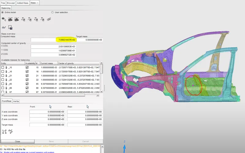
The highlighted number is the mass of the model in tonnes. Which is 7 tonnes or 700KG. In the circled portion, the pink dot is the CG of the model.
Now the contact is to be defined. Type 7 contact is preffered for the crash applications. It defines node to surface contact(self contact).
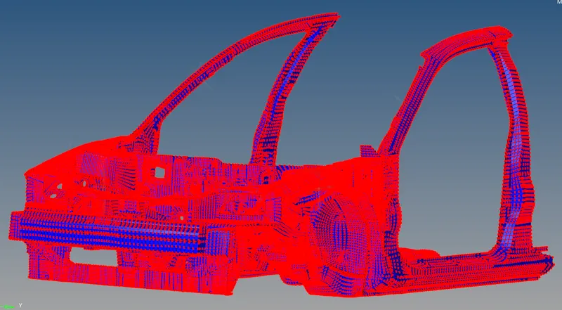
For determining the axial force recieved at the rails from the bumper, a contact is defined between the bumper and rails.
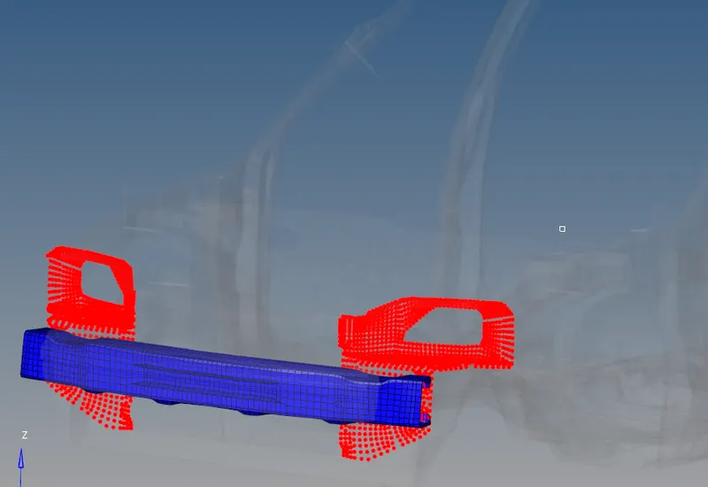
Initial velocity of 35mph or 15.6m/s is given to the vehicle.
Rigid wall is created using Rwall plane. A search distance is given for determining the slave nodes near. The nodes within the search distance are seen in yellow in the figure below.
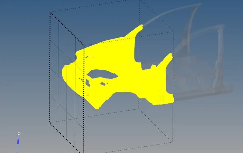
After all this etup of the model, it is imported in Hypercrash again in order to check for errors in the model. There were some unused and unwanted elements and skews which are deleted and errors are eliminated.
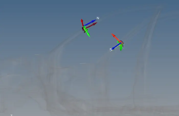
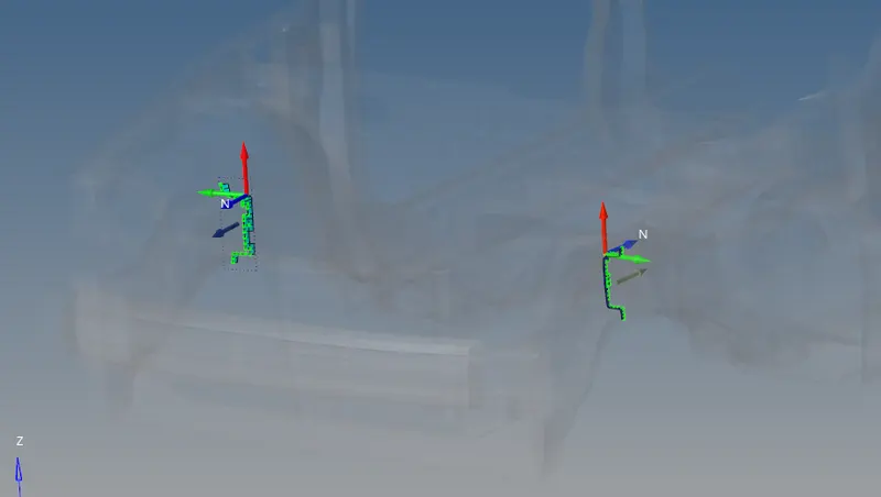
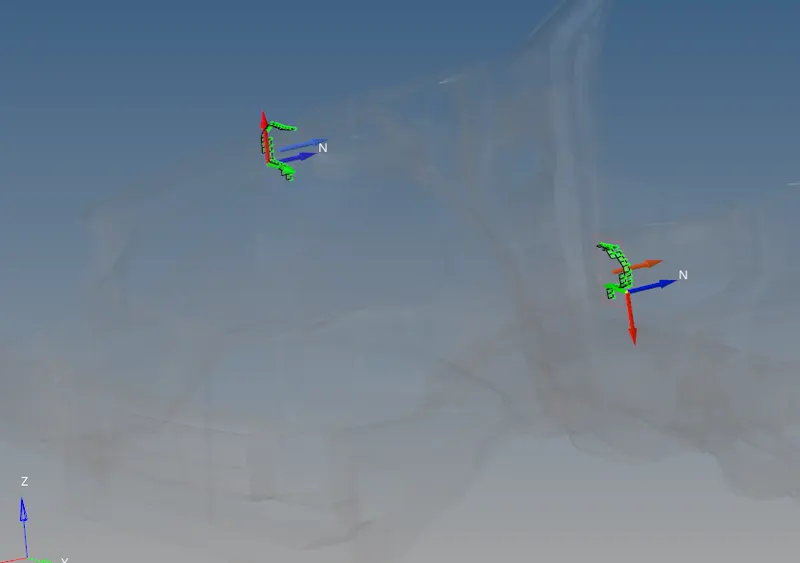
One of the output requests is the cross sectional forces through the A pillar, Shotgun and Rail components of both sides.
A frame is defined for the direction of the force and cross section elements are specified through which the force is to be measured.
A pillar cross section.
Rail cross section.
Shotgun cross section.
 7
7
The mentioned cross sections on both left and right side will give the force magnitude passing through.
The timestep of the model is 0.5ms and the runtime is 80ms.

After all checks, this model is exported and opened in Hypermesh again in order to solve in Radioss.
Under Analysis:Radioss, a location directory is specified for the solver to print the results. Under options (-nt 4) is used to speed up the solving process by multithreading. As this is a student version of the software, the number of threads can be used till 4 only.
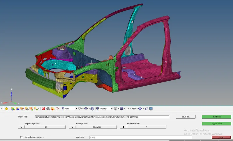
After solver job is completed, it will show the time taken to complete the job and number of cycles.
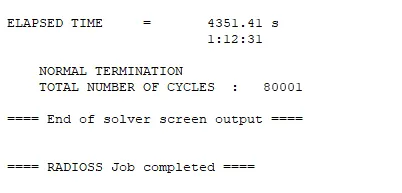
Simulation time: 4351.41 sec
Number of cycles: 80001
Solver has successfully completed the simulation.
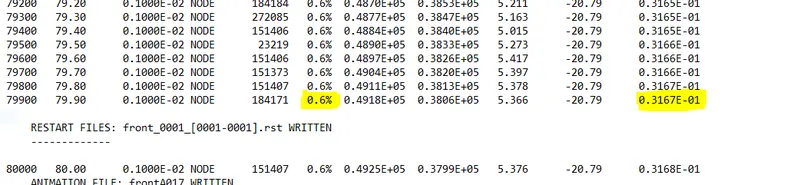
The 1.out file will show the energy error and mass error. As per the results for this simulation, the energy error is 0.6% and mass error is 31.67grams. This mass error is due to mass addition at nodes in order to increase the time step which was falling.
The case setup and execution has been discussed, now lets look at the results.
Results:
The output results to be checked for the simulation are:
1. Sectional force in the rails at location of indicated node 174247.
2. Axial force received on the rails from bumper.
3. Shotgun cross sectional forces.
4. A pillar cross section.
5. Acceleration curve received on the accelerometer at base of B pillar (on B pillar rocker).
6. Intrusions on the dash wall 66695,66244.
The significance of these forces is that the distributuon of the forces while passing through the body is determined.
Sectional forces:
Cross sectional force in Left and Right A pillar:
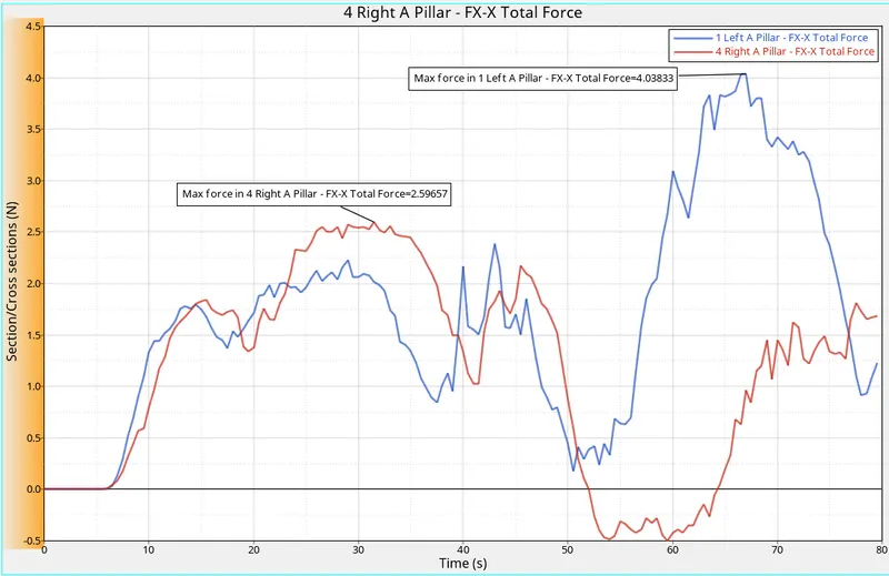
The maximum force that went through the left A pillar is 4.038KN. And through Right A pillar is 2.596KN.
For right A pillar the plot goes in negative too. This implies that the force is transfered to the front again.
From this we can say that the left side is going to have high impact force compared to right side, and it can be serious matter during an accident.
Cross sectional force in Left and Right Shotgun:
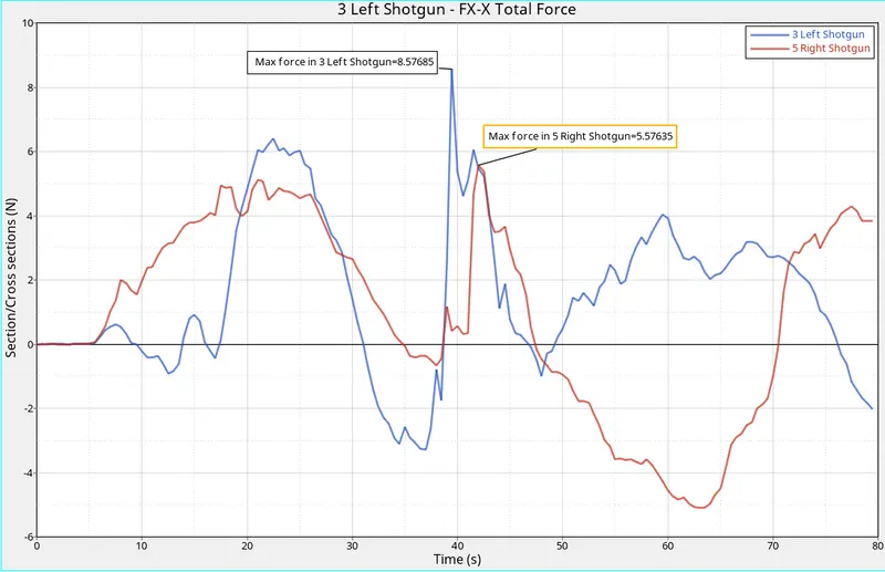
The maximum force travelled through the cross section in the left shotgun is 8.57KN. And through the right shotgun cross section is 5.57KN.
In both the sections the force is negative as well as positive. This negative force implies the reverse travel of the force towards the wall.
Cross sectional force in Left and Right Rails:
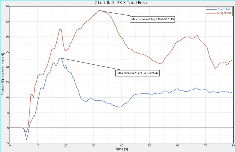
The rail forces in leaft and right side are seen in the plot above.
The maximum force through the cross section in the left rail is 22.99KN, and in right is 38.61KN.
A maximum amount of the force is passed through this component.
This was about the sectional forces through the A pillar, Shotgun and Rail.
Axial force recieved on rails from the bumper:
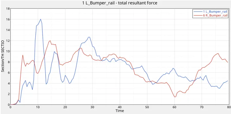
The force recieved from the bumper to the rails is plotted in the graph above. The maximum force recieved in the left rail is 16KN and in right rail is 12KN.
During the impact, force acts on the bumper and it deforms as much as it can and transfers the force when it can't deform. This force is transmitted to the rails.
The accelerometer readings:
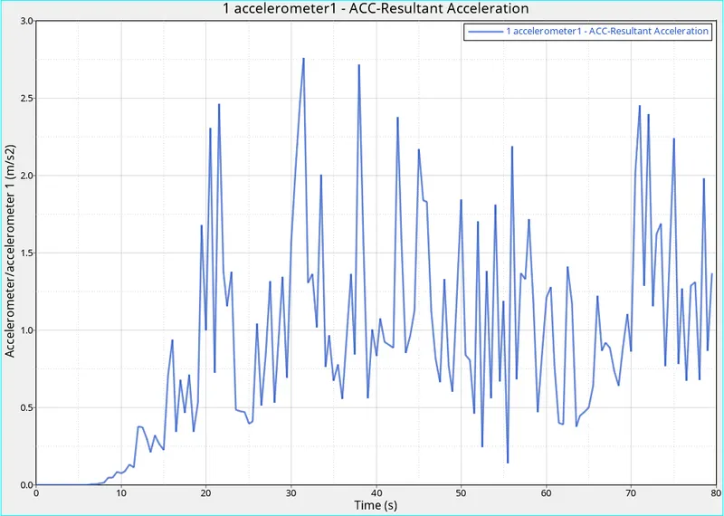
This is the accelerometer reading at the bottom of the B pillar.(on the rocker below the B pillar)
It is showing the resultant acceleration at the rocker. The acceleration is used to calculate the injuries. Since there are no dummies we are placing the accelerometer at the rocker.
Intrusion of the mentioned nodes.
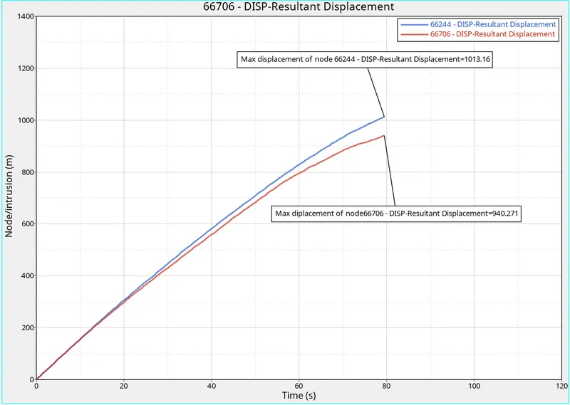
The nodal displacement of the mentioned nodes is 1 to 0.9m. The method used to determine this intrusion is by defining the output of the nodes in TH with repect to a fixed skew. The diplacement value in the graph is the distance between the node and the reference skew.
Energy plots:
Total energy, internal energy and kinetic energy of the model is ploteed in the graph below.
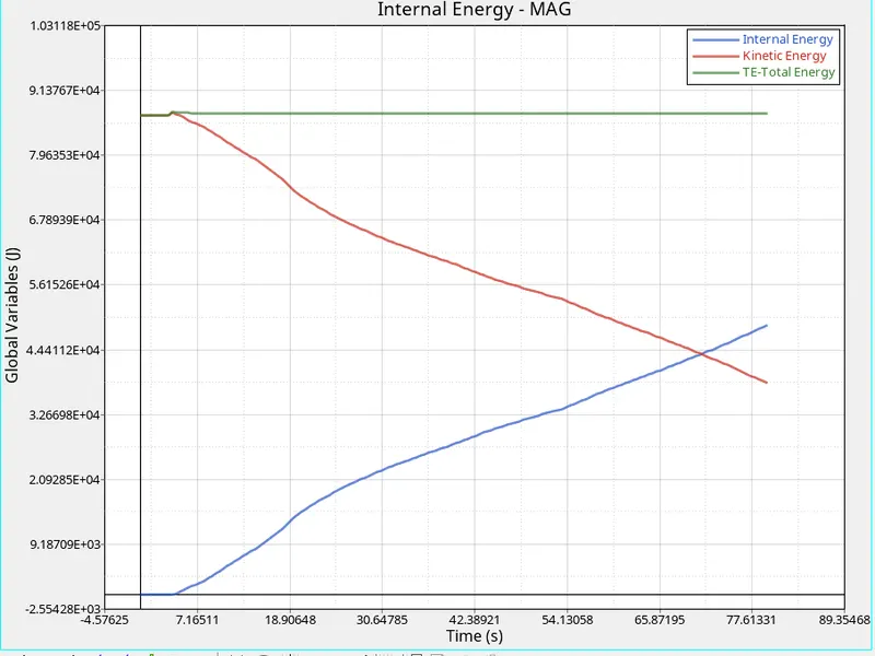
The Kinetic energy of the structure is 85176 J, since mass is 700kg and velocity is 15.6m/s. We get 1/2*m*v^2 as 85176 J.
The total energy is the sum of kinetic energy and internl energy.
As the structure impacts o n the wall, the kinetic energy starts to convert in internal energy of the structure as it is deforming and absorbing this energy. Hence the total of the two is same throughout.
The animation of the crash is attached below.
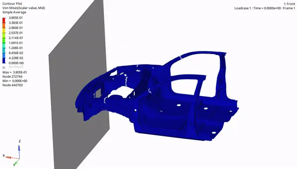
The maximum vonmises stress is 380MPa.
The front parts like the bumper, rail, shotgun and other parts which are before the A pillar are deformed very much. This ensures that maximum of the impact forces are damped here itself by absorbing the energy by deforming. The passenger compartment is not much deformed but tilted. Hence we can say that the structure is carshworthy.
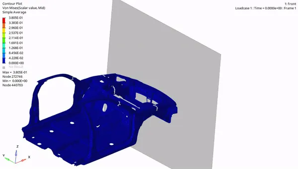
While deforming the body is tilted but the floor panel is horizontal till the end. This is because of the rigid section at the bottom of the floor panel.
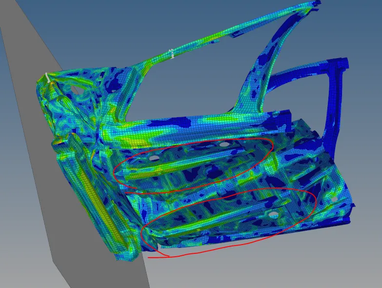
The rigid beams at the bottom ensures that the floor panel is not deformed and crushed. Otherwise the passengers in the car will meet heavy injuries.
Conclusion:
The frontal crash simulation of the given BIW structure is done using Hypermesh and Radioss. Use of Hypermesh tool is done in preprocessing of the model and setting up the solver. The Radioss solver is inbuilt in Hypermesh. Radioss is used to solve the case. After solving, the results were analysed with the help of Hyperview and Hypergraph. This is the post processing state where the results are understood with the aid of post processors which present the results in easy and readable way.
The link to download the simulation files is attached below.
https://drive.google.com/drive/folders/1r4inFszG3yr7DVxxEeBYkpLK8FEc1SnL?usp=sharing