Side Crash of a car's BIW structure using Hypermesh and Radioss
Aim: To perform side crash analysis of a car's BIW structure using Hypermesh and Radioss to determine its crashworthiness.
Objectives:
- Check unit system and either follow [Mg mm s] or [Kg mm ms].
- Create appropriate interface ,friction 0.2 and recommended parameters.
- Make sure of no penetration and intersections.
- Create rigid wall with friction 0.1 as per referance model.
- Compare the model weight with the referance model and use added masses to reach target weight 700kg while getting CG about the required range.
- Initial velocity as shown in picture.
- Use model checker to ensure good quality.
- Timestep :0.5 to 0.1 microseconds.
- Run 80ms.
Output requests:
- Sectional force in the cross member.
- Intrusion at B pillar,hinge pillar and fuel tank region.Provide recommendation on what can help to reduce Fuel tank intrusion.
- Peak velocity of inner node of the door.
Introduction:
This project aims at performing side crash analysis of a car's BIW structure using Hypermesh and Radioss. The simulation results will help determine the forces that travel through the different cross section in the vehicle body. The intrusions that can harm a passanger can be determined with the simulation results. The effect of creash on the fuel tank can also be guessed with proper analysis. Thus changes can be made in the model prior to the manufacturing, as required.
If it was not for these type of CAE tools, there would be a lot of capital investment and wastage of money. A prototype costs upto ten times more than the mass produced car. Also, there are number of prototypes for crash analysis. If the crash results are not acceptable, more crash tests are performed with improved prototype. CAE helps in reducing the physical prototype cost.
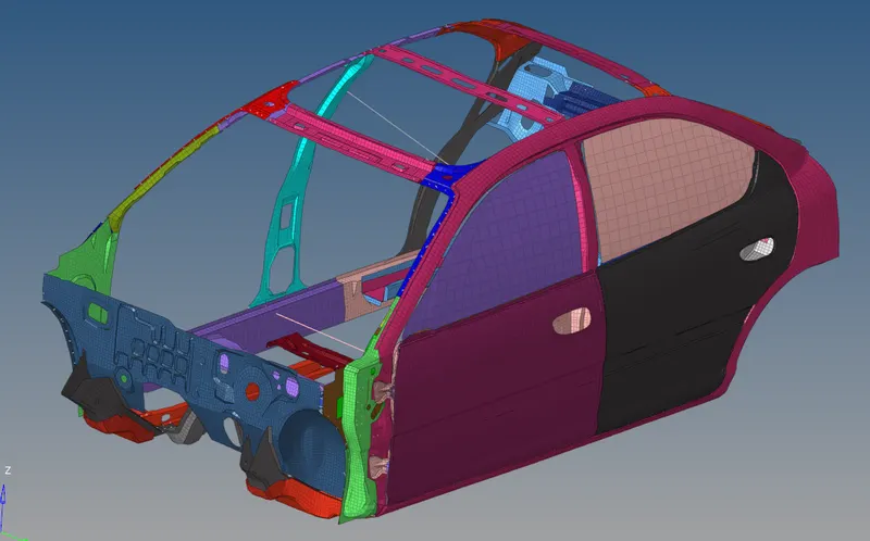
In this project, a Neon BIW is used for side crash.
Case Setup:
A crash analysis, or any type of FEA simulation requires three main tools. Preprocessor for mesh generation and setting the boundary conditions, a solver to simulte the case and solve it, and a post processor to analyze the results. These tools are Hypermesh as preprocesser, Radioss as solver and Hyperview and Hypergraph as post processors.
The starter file of the model is imported in hypermesh. It is checked for initial penetrations first. It causes contact error in the simulation and interface definition will be incorrect.
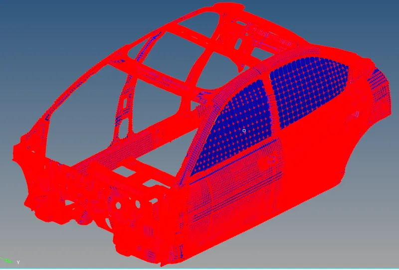
The model used is a reduced model due to the limitation of the student version. The number of nodes is limited to 100,000 in student version. Hence the model is a reduced one. The mass of the model for this crash should be minimum 700KG. Our model has a mass of 166kg. There is a need to add mass to the model. A total mass of 534KG is to be added to the model to get minimum 700KG. On selected cross sectional parts, this mass is added.
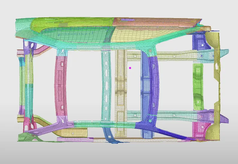
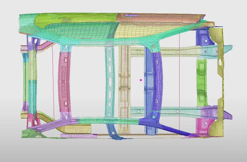
The position of CG is also of prime importance. As the model is reduced the position of CG is also disturbed. By comparing the CG of this model with the full model, we need to add mass in such a way that the CG is moved to its original position. The image below shows the old and new position of CG.
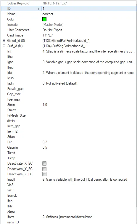
There is contact defination in the model. Type seven interface is defined in the model, which is self contact, nodes to surface contact. The coefficient of friction in the interface is 0.2.
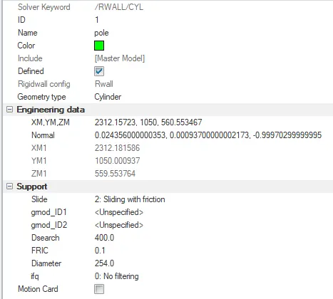
A rigid pole is defined using Rwall:cyl. The standard diameter of the pole is 254mm. The sliding flag is set to sliding and friction with 0.1 friction coefficient. The search diameter is 400mm to get the slave nodes position. The length of the pole is infinite.
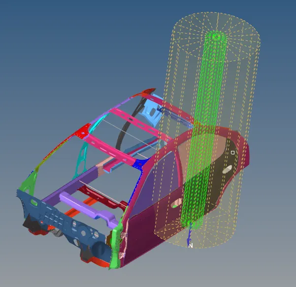
Now that the model setup like the Rigid wall definition, interface definition, mass balancing etc. is done, we will focus on the output requests from the model.
Sectional force in cross members:
A cross section is created on the member where sectional force is required. SECT option is used under solver deck to createthe cross section on the required part. For each section, a frame for reference is to be defined. This is how the section looks with reference frame.
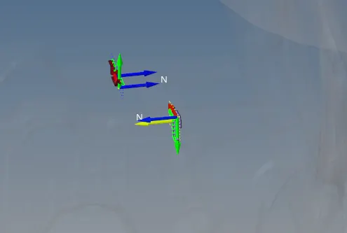
The maximum force in the normal direction is what we want in result.
Intrusion:
Intrusion in the defined areas can be calculated in two ways. Defining the node in TH with a reference skew, and defining a spring between the nodes where the elongation will tell the intrusion. Here, spring method is used. The parts where intrusions are to be measured are B pillar, hinge pillar and fuel tank region. These are the critical areas where the passengers will be at risk and the fuel leak can cause fire risks.
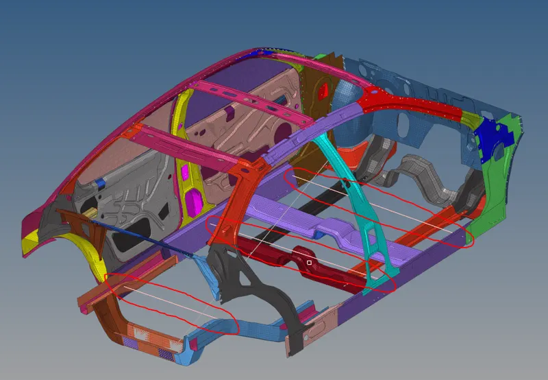
Spring are created in these parts and their elongation is measured in that direction to get the intrusions.
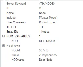
The peak velocity at the node mentioned on the door is to be measured. If the node is moving inside the car(toward the passenger), we can know the extension of the injuries it might cause.
To get the velocity at this node, in time history card this node is specified for default results which include the velocity, displacement, moment etc. for that point. This node is specified in the outputblock.
Run time and time step:
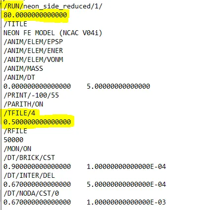
Run time is 80ms and time step is 0.5ms.
After all the setup of the model it is checked for errors using hypercrash application(Quality:Model checker:Run).
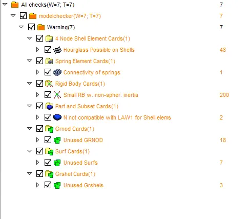
There is no error found and we are ready to run the simulation using Radioss solver.
In Hypermesh we have the Radioss solver under Analysis tab. We can use multiple threads for increasing the simulation speed. However, student version allows use of upto four threads.

By clicking Radioss simulation begins.
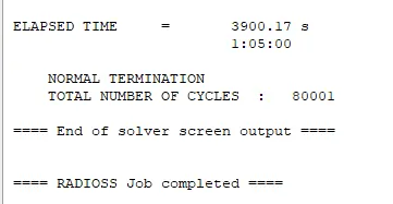
After complition of the simulation, this is the message displayed. It tells the time solver took to simulate the complete case and the total number of cycles. There were 80001 cycles and time required for simulation was 3900 seconds.
Results:
The animation of the crash is attached below. It is opened in Hyperview with .h3d file. It shows the actual visual representation of crash. The VonMises stress can be plotted in the model with maximum and minimum stress in the elements.
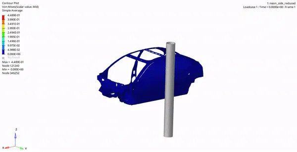
The maximum stress in the model is 448MPa. The vehicle actually bends from the pint of contact. It is deforming continuously from the front and rear side. Also the sections under the passengers is getting deformed and is bending in upward direction. If this was a electric vehicle the battery position would matter a lot, as it is in the bottom area mostly.
1.Sectional forces:
The sectional force is used to determine the amount of force passing through the cross section and how the force is distributed in the model. There are two sections along which the sectional force is to be determined. Both these sections are cross members of the chassis located in the centre of the vehicle at B pillar and below the front compartment.
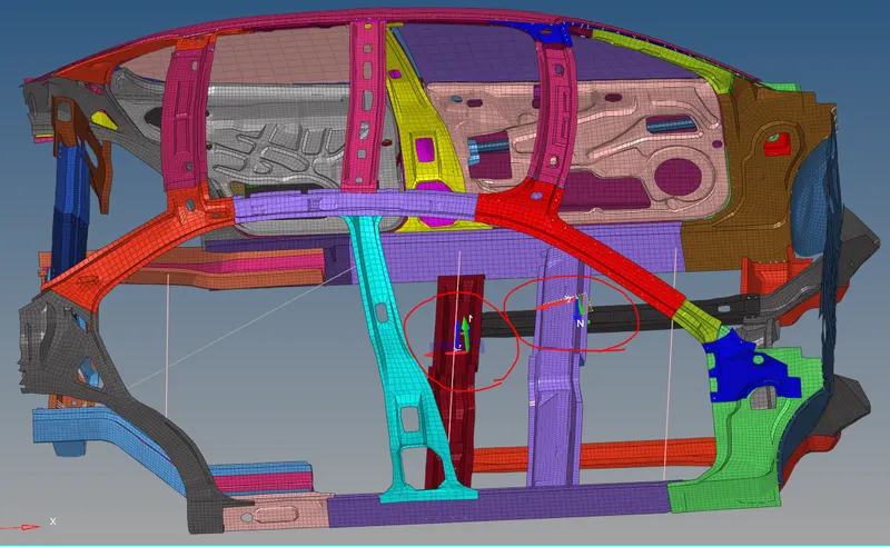
The results of this are viewed in the hypergraph window.
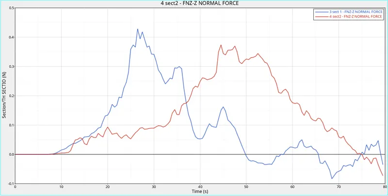
The blue colour line shows the graph of the 1st section(the one at B pillar). The peak force in this section is 420MPa. The other line shows the force in 2nd secton. It has peak force of 375Mpa.
There is also negative force seen. This conveys that the direction of force is towards the pole also.
2.Intrusions:
The intrusions are measured in three parts with the help of springs. The elongation in the springs is the intrusion of the nodes.
This determines the amount of ntrusion in that part at that node. The graph of this is attached below.
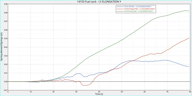
The intrusion for three nodes is plotted here. The highest intrusion of 82mm is seen in the tank region. Intrusion of 50mm at the hinge pillar is seen in the plot. The B pillar has intrusion of 24mm.
The tank intrusion is a vulnerable and needs to be taken care of. Hence the material used for tank should be impenetrable as much as possible. A fibre reinforced tank can be used. This type of tanks are highly resistive to penetrations.
3.Peak velocity of inner node of the door:
The velocity of that node throughout the simulation will tell its effect on the passanger sitting at that door.
The velocity graph is plotted below.
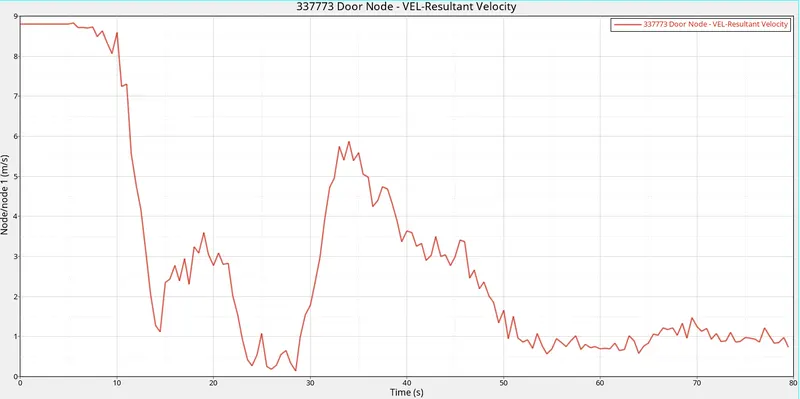
The velocity of the vehicle before impact was 8.8m/s. As it impacts, the velocity reduces. Similar behaviour is seen in the node. The velocity of the node again increases as the body collides into that portion.
4.Energy error and Mass error:
The energy error and mass error is seen in the 0000.out file. The energy error is -1.8% and mass error is 5.8gram.

5.Internal, Kinetic & Total enery:
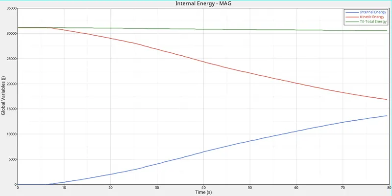
The Kinetic energy of the model is 30,976 J. K.E.=0.5*m*v^2.
where,
mass=750kg;
velocity=8.8m/s;
The Internal energy in the model is zero initially. As the impact happens, the kinetic energy is converted to internal energy of the model as it deforms and absorbs the energy. The total energy is the sum of the internal energy and kinetic energy. Hence it seen to be almost constant.
Conclusion:
The side crash test is carried out using Hypermesh and Radioss. The results are analysed using Hyperview and Hypergraph and explained. The output results like the Peak velocity of the inner node of door, sectional forces and the intrusions are viewed and plotted successfully.
Below is the drive link to download the simulation files.
https://drive.google.com/drive/folders/1YJa_HsEGZXrqEKzloAB8vZZQ9gvq5maA?usp=sharing