Meshing Front Suspension System and Providing Connections
Aim: For the given assembly, checking for the geometrical errors and meshing it with the given element Quality criteria. After meshing the component, thickness has to be assigned for mid surfaces. Tetra elements are to be used to model non-uniform thickness components. Also, connections are to be made to connect the components.
Introduction:
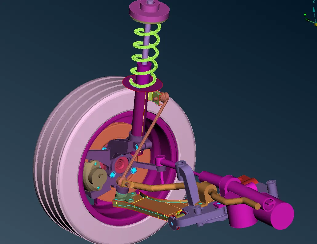
The assembly taken for this project is a suspension system of a front wheel. There are many types of the suspension system used today and the one in this project is the Macpherson strut. The MacPherson strut is a type of automotive suspension system that uses the top of a telescopic damper as the upper steering pivot. It is widely used in the front suspension of modern vehicles and is named for American automotive engineer Earle S. MacPherson, who invented and developed the design.
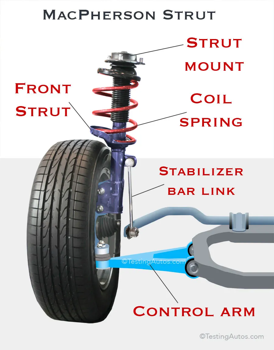
This suspension system has the following parts included.
1. Spring and damper
2. Steering knuckle
3. Tie rod.
4. strut, spring plate, strut bearing
5. wheel hub
6. Disk(brake), and Disk calliper
7. Tyre & Rim
8. Lower control arm
9. Subframe
10. Anti roll bar (sway bar)
To mesh all the parts mentioned above, considering the thickness and selecting the proper method for meshing is very important to ensures more efficiency and time saving. The parts having same thickness throughout cross sections can be meshed by tria and quad on the midsurface and those with different thickness values can be meshed by tria and ortho tria elements on the surface and then creating the volume and meshing it with Tetra Rapid or Tetra FEM algorithm to get volume mesh.
Procedure:
Let's discuss stepwise procedure to deploy mesh on the parts of our component.
1. Geometry cleanup.
Once the component is imported in ANSA, it is stitched together by performing topo on the geometry.
TOPO Deck : Faces : Topo
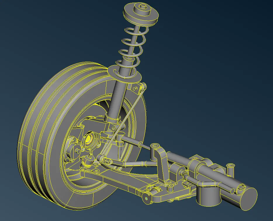
Check for the geometric errors.
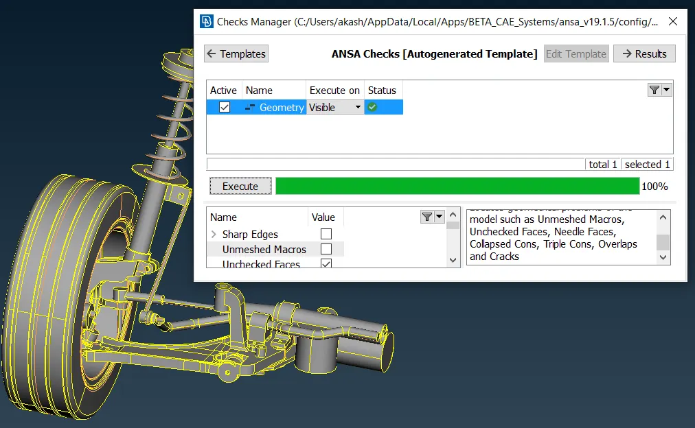
Checks : Geometry : Execute
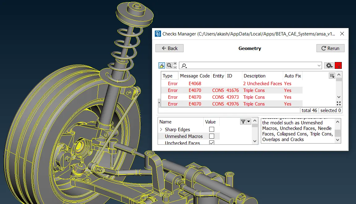
Majority of the errors are triple cons. They are formed as a result of three surfaces being attached together. One of which may be the unwanted duplicate face. Unchecked are the unneccesary extra faces that can be deleted. This way, all the errors can be eliminated from the geometry. The below image shows the result when all the errors are removed.
2. Providing parts with their identities.
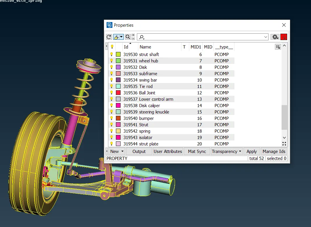
The given component itself is a system and contains many parts. It is suggested that different parts should be provided with their different identities for simplification.
Example: Spring is provided with different PID. Strut is provided with different PID. Tyre and rim both are provided with seperate PID. etc.
Every part has its own thickness and material, hence setting PID determines the simplicity of the work.
3. Meshing.
As mentioned earlier, solid and shell meshing both will be employed in this case. Parts with non uniform thickness by solid meshing, and parts with uniform thickness will be meshed by shell mesh method on its midsurface.
Shell Mesh:
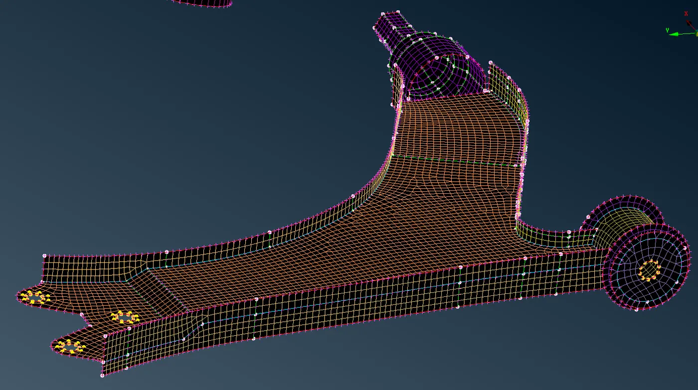
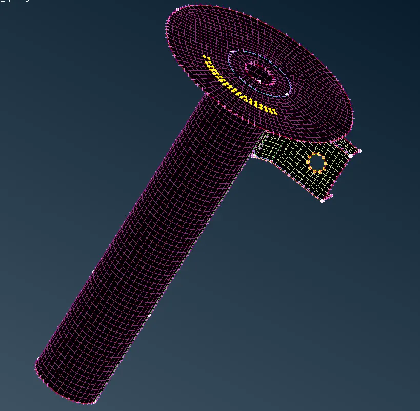
The lower control arm, strut, and the a plate used to connect strut with the swing bar are the only parts with uniform thickness. These parts are midsurfaced first and PID is assigned with proper thickness. These parts are then meshed according to the quality criteria provided.
Quality criteria for Mixed elements (For Midsurface only):
|
S.No |
Quality Criteria |
Value |
|
1 |
Target/Average length |
4 |
|
2 |
Minimum Length |
2 |
|
3 |
Maximum Length |
6 |
|
4 |
Aspect |
3 |
|
5 |
Warpage |
15 |
|
6 |
Skewness |
45 |
|
7 |
Jacobian |
0.7 |
|
8 |
Minimum Quad Angle |
45 |
|
9 |
Maximum Quad Angle |
135 |
|
10 |
Minimum Tria Angle |
30 |
|
11 |
Maximum Tria Angle |
120 |
All the above criteria are fulfilled in the elements of mesh. The image below shows the midsurfaced parts along with the mesh.
Solid Mesh:
All the part except those mentioned above will be solid meshed. The steps included are as follows.
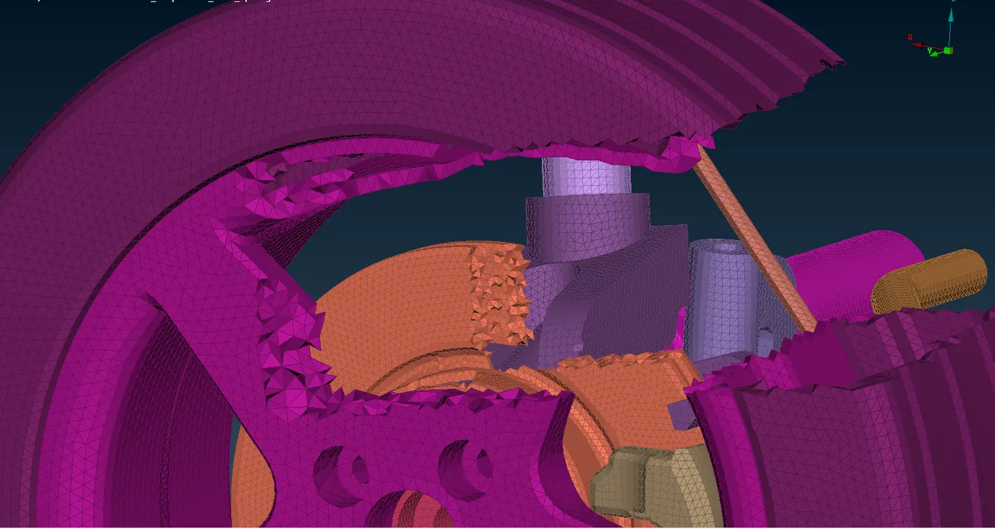
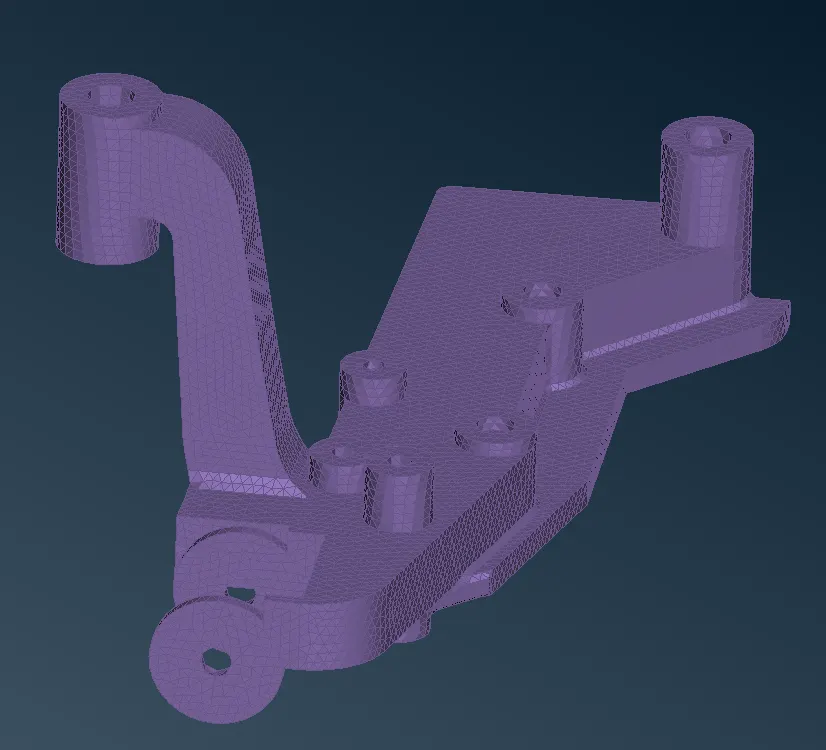
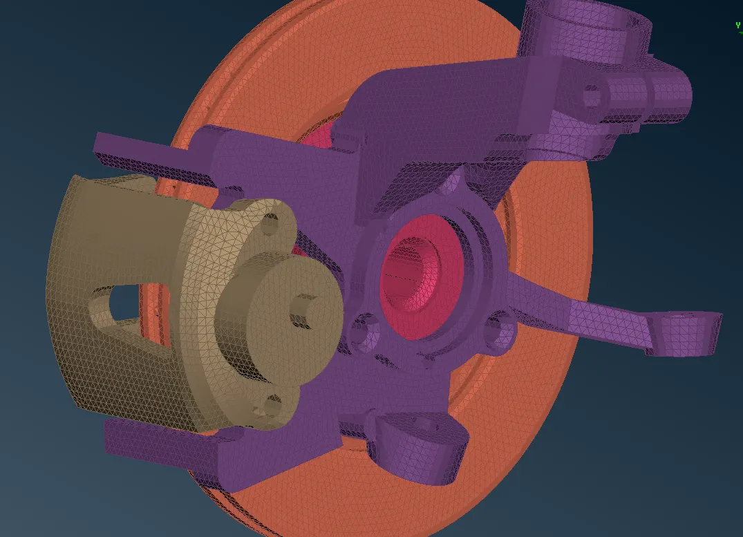
1. Meshing the outer surface of the volume with trias and ortho trias. Trias are used on flat surfaced and ortho trias on the curved surfaces to capture the features accurately. The mesh is also checked for the quality criteria given for trias in solid meshing.
2. After meshing the surfaces w.r.t. quality, the meshed part is listed in the volumes list by defining the volume in Volume Mesh Deck : Volumes : Define : Manual. New window appears for assigning PID to the volume. Assign the new volume PID.
3. In the list, the new solid will be seen unmeshed. Selecting the remesh option and then either of the meshing methods, the solid mesh is generated. The meshing methods for this type of mesh are Tetra FEM and Tetra Rapid. To choose either of them depends upon the user.
Following the above procedure the solid mesh is created.
For tyre and rim the quality criteria is different and for all the other solid parts it is different.
Quality Criteria for Tria Elements (Tyre and Rim):
|
S.No |
Quality Criteria |
Value |
|
1 |
Target/Average length |
6.5 |
|
2 |
Minimum Length |
5 |
|
3 |
Maximum Length |
10 |
|
4 |
Skewness |
45 |
Quality criteria for Tria (For other components):
|
S.No |
Quality Criteria |
Value |
|
1 |
Target/Average length |
4 |
|
2 |
Minimum Length |
2 |
|
3 |
Maximum Length |
6 |
|
4 |
Skewness |
45 |
Common Quality Criteria for Tetra elements are:
|
S.No |
Quality Criteria |
Value |
|
1 |
Tet-collapse |
0.2 |
All the tetra elements in all the solids are checked for the tet-collapse failure. This off elements are eliminated by the use of MV Free option in the Mesh module, by moving the nodes of the element in order to get the perfect shape of the elemet. Fix Quality option in the Volume Mesh module is also used for the same purpose. The kinks and raises are major issues to be monitered for solid meshing. They should be compulsorily removed from the surface.
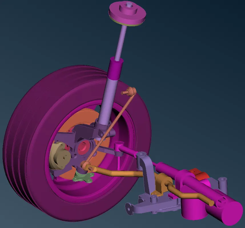
Below images show some of the solid meshed parts.
4. Connections:
Point, Curves and Faces are used to define Spotwelds, Rivets, Bolts, Seamwelds, Adhesives, Gumdrops, and many other types of fasteners inside ANSA. These are managed through the Connection Manager, which allows the analyst to define templates and use multiple built in definitions for the different FE representations.
The type of connection employed in this assembly are bolts mainly, and a weld to join a plate to the strut to connect the swing bar. The brake disc is connected to the wheel hub with bolts. The wheel hub and steering knucke are also connected with bolts. Anti roll bar(sway bar) and the steering mechanism supports are mounted on the subframe by bolt joints.
All the mentioned parts are using bolts, hence bolt joint is provided there with the help of 1D elements in the Nastran Deck : Elements : RBE2 : Many Nodes.
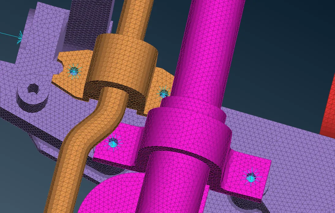
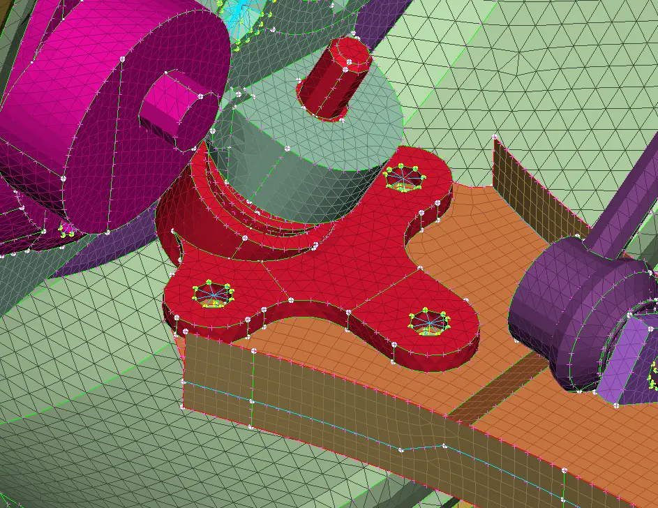
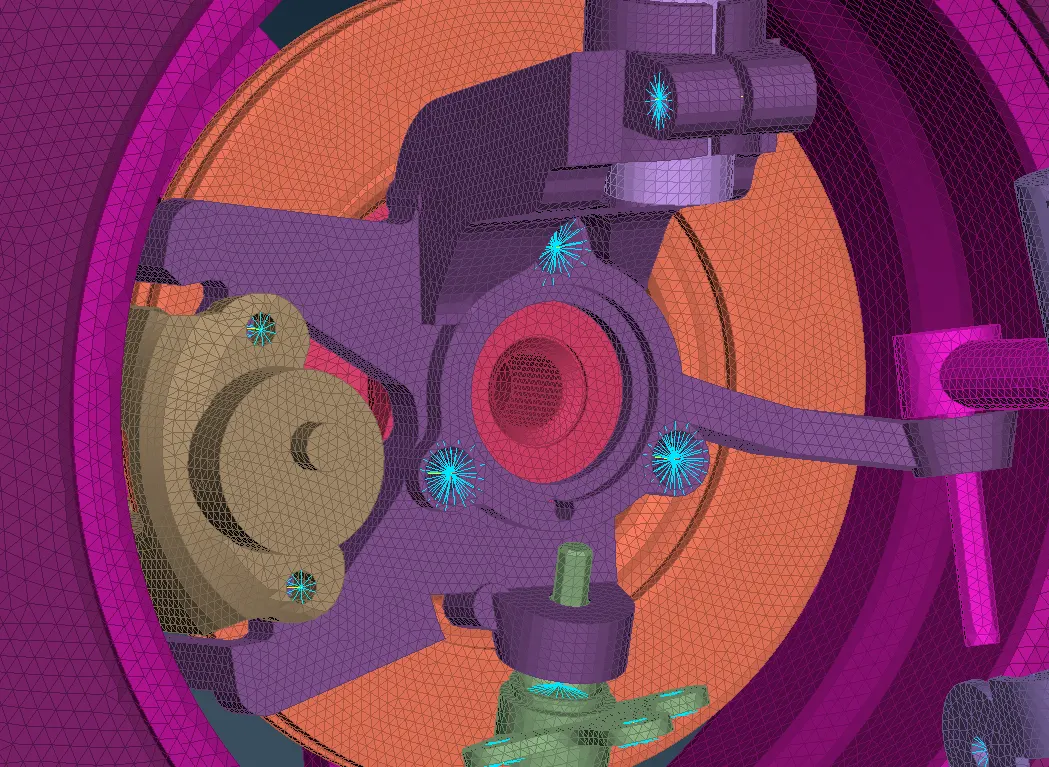
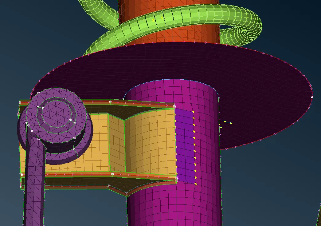
Bolt connection between Knuckle, Disk calliper, Disk, Wheel hub etc. Weld connection between the strut and plate.
The coil spring in the suspension is modeled with the help of 1d elements, to which the area on the coil is given and the 1D element acts as the axis of the coil.
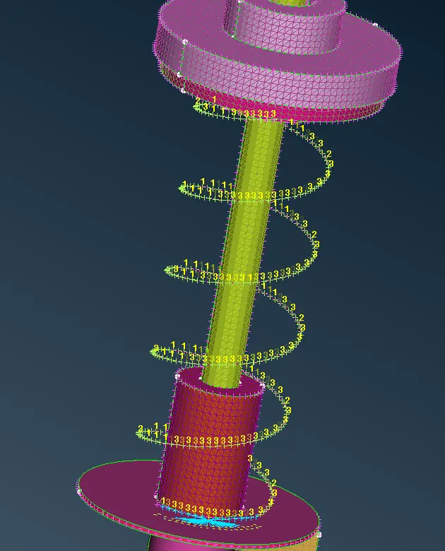
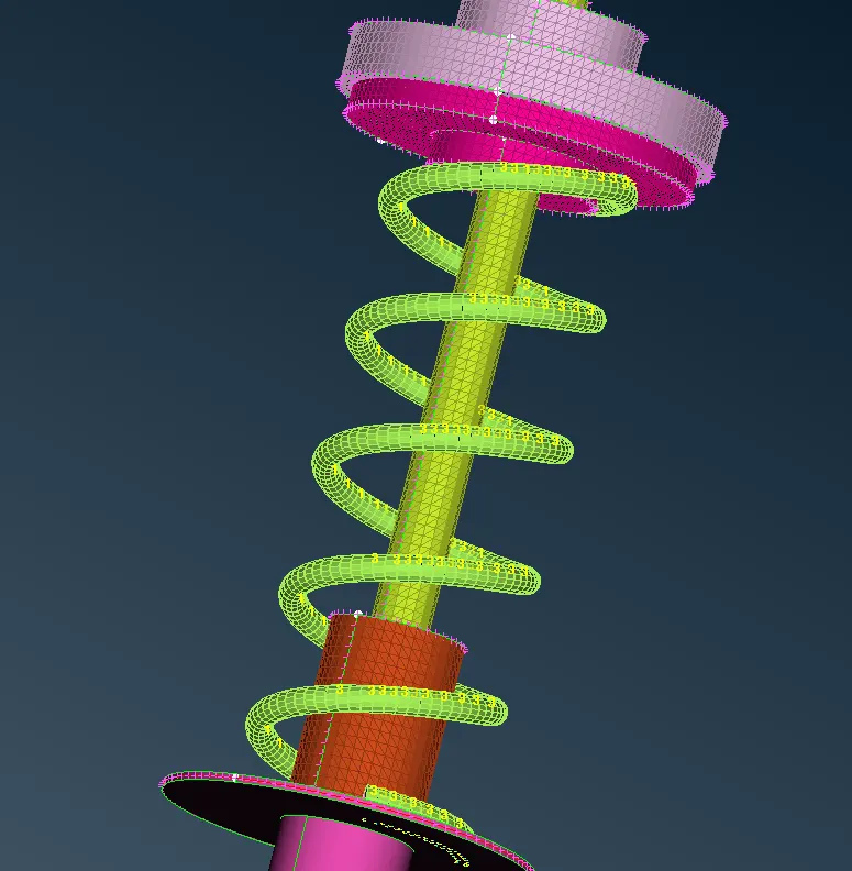
This is how the meshing and connection of the given component is done. The below image shows how the component looks like.
Learning Outcomes:
This project requires application of most of the tools and commands learned in the course. Cleaning gometry manually is learned. Setting PID for differenr parts is achieved. Midsurfacing practise is done in this project. Meshing on the parts is practised in order to minimize the tria percentage in the shell meshing and maintaining the quality criteria. Volume meshing is practised and well achieved. Connections with RBE2 Many nodes and Two nodes is well learned. Use of CBAR elements to model the spring is done.
Conclusion:
To conclude, the geometry clean up, meshing the parts of the system with shell mesh and solid mesh , providing connection on the required parts, all was achieved by keeping in the view the quality criteria for every scenario.
The suspension system is quite a challenging area to work on. After working on this project one can gain more confidence, and find it easy to work on other models.
Link to download the suspension model.
https://drive.google.com/file/d/1Vhg6jB-sENPq_1ME454Y5jLNozrV-LBk/view?usp=sharing