Midsurfacing | Meshing | IP substrate of car | ANSA Preprocessor | Structural Analysis
Aim: For the given Instrument Panel substrate, checking geometrical errors and meshing it with given quality criteria is the objective to accomplish.
Procedure: The Instrument Panel is a surface in front of a driver's seat, on which the vehicle's instruments are situated. These IP's are plastic components having very thin and complex designs that create housing for number of equipments including the Airbags and electronics. As this is a plastic component, it is maily checked for NVH failures.
As the IP is a thin plastic component, it can be midsurfaced and a 2D mesh can be performed on it. Every time the thickness changes, the new midsurfaced part is to be assigned a different Property ID and the respective thickness in the respective PID.
Step wise procedure for preprocessing the given component:
This is how the component is right after importing into ANSA.
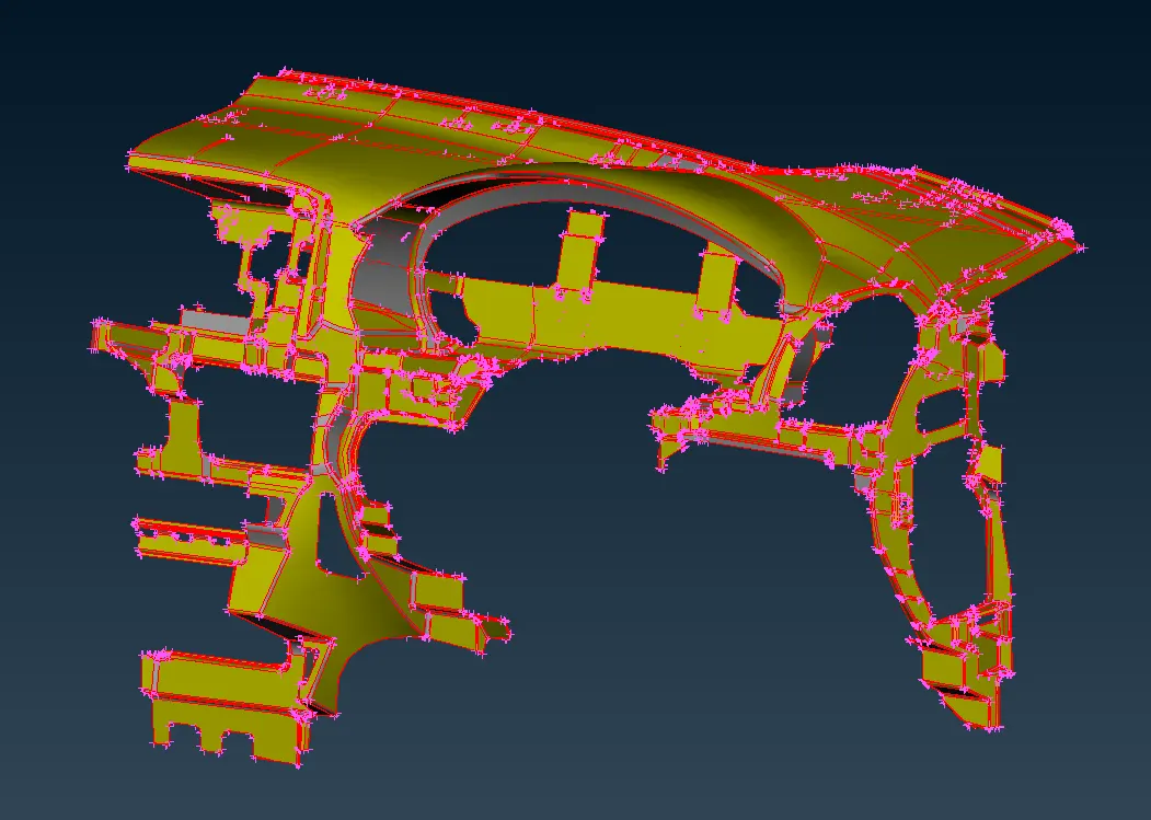
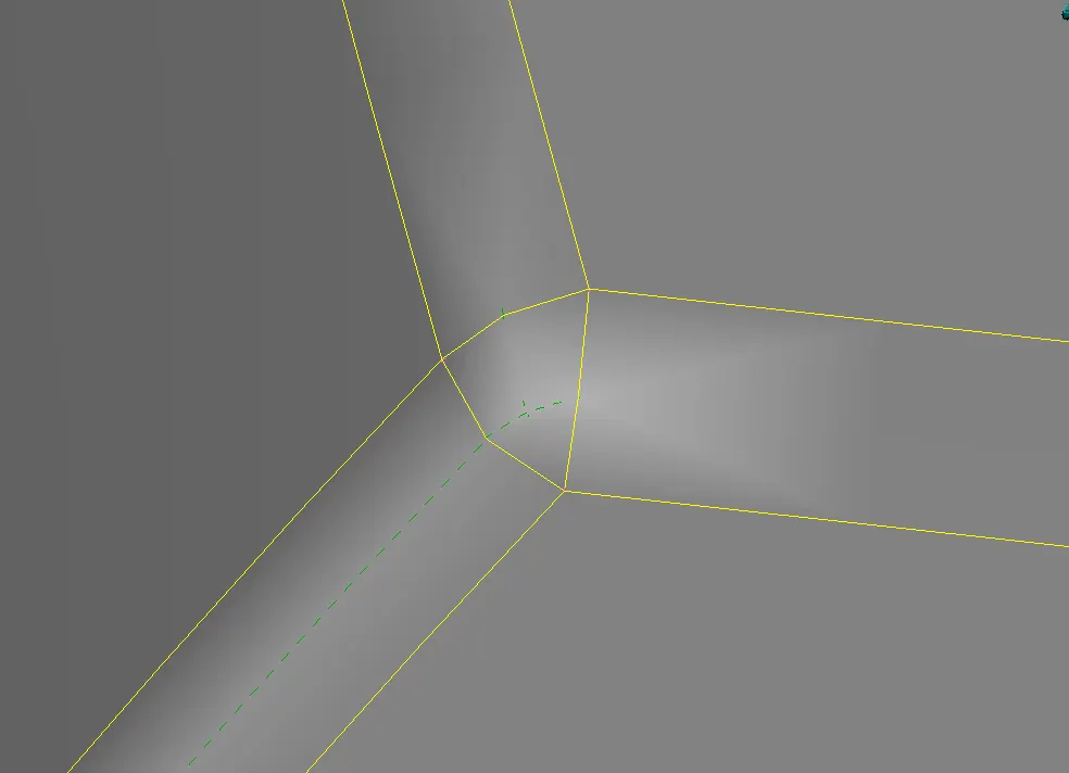
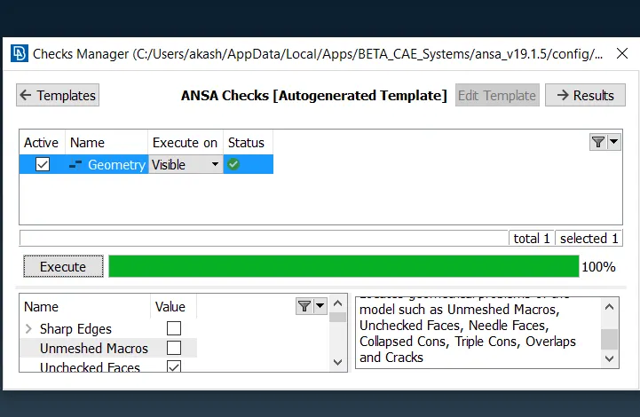
1. Geometry cleanup: The first and one of the most important steps in preprocesing is, understanding the geometry and its application. For taking a clear view of the geometry, the perimeter and macros length is set as low as 1-5. This makes the geometry look more clean and fine, showing all the features clearly. Then perform a topo in the geometry and check for geometric errors. In this component, distorted surfaces around the curved features was the main error found in large numbers. Following this, 210 unchecked faces, i.e. extra faces after performing topo, were a big problem.
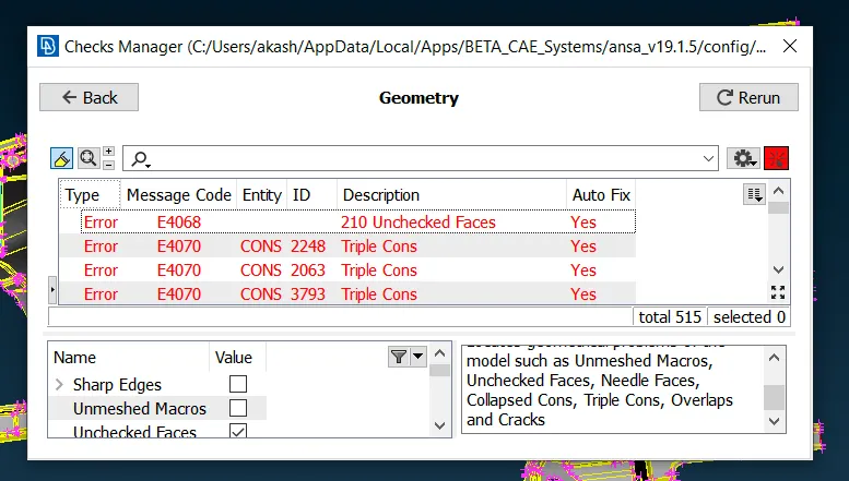
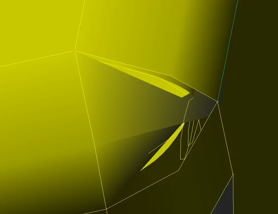
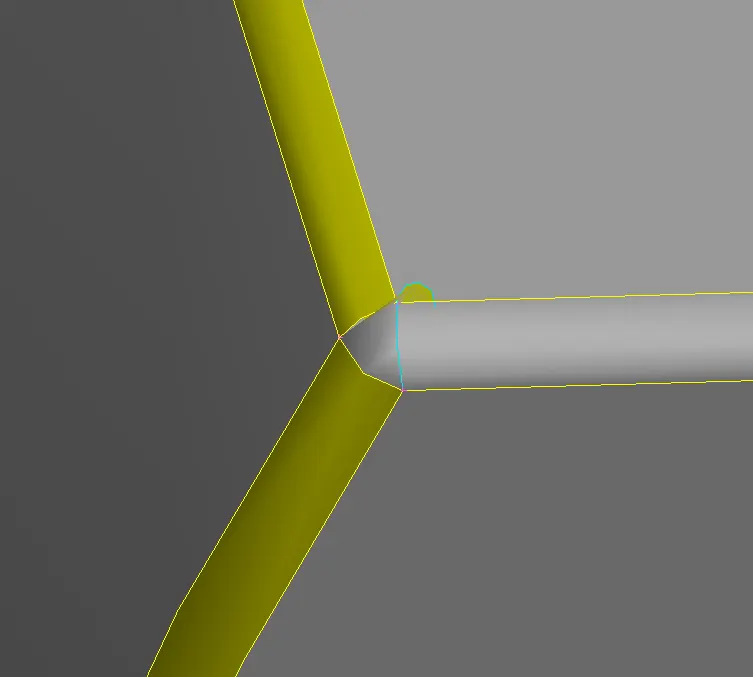
These are the errors found in the geometry. After cleaning the geometry, all the errors were eliminated and the below image shows the clean feature w.r.t. the above error.
2. Midsurfacing: Midsurfacing is a process of converting a 3D model to 2D in order to simplify meshing and reduce the time required for simulation. This does not mean thickness elimination, but it is assigned to the respected part in its PID.
The outermost sheet of plastic is of 0.6mm thickness, on which other parts of different thickness like ribs are present. This outer sheet can be first midsurfaced using manual offset option to 0.3mm. Other features like ribs are offseted after it. The images below shows the 3D part and its 2D representation as a midsurface.
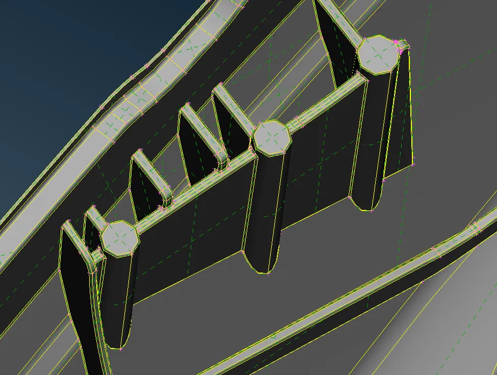
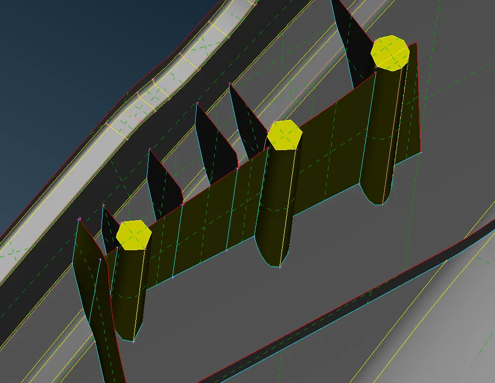
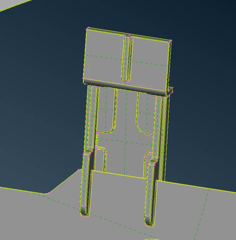
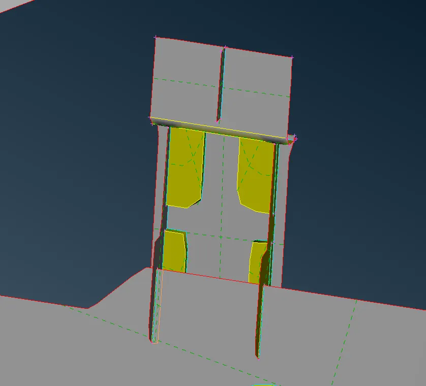
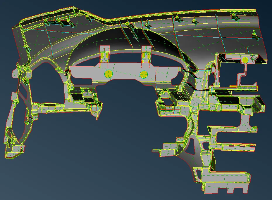
Similarly, overall midsurfaced component looks as shown in the image below.
3. Meshing: The midsurfaced part is ready to be meshed with respect to the given quality criteria.
|
S.No |
Quality Criteria |
Value |
|
1 |
Target/Average length |
4 |
|
2 |
Minimum Length |
2 |
|
3 |
Maximum Length |
6 |
|
4 |
Aspect |
3 |
|
5 |
Warpage |
15 |
|
6 |
Skewness |
45 |
|
7 |
Jacobian |
0.7 |
|
8 |
Minimum Quad Angle |
45 |
|
9 |
Maximum Quad Angle |
135 |
|
10 |
Minimum Tria Angle |
30 |
|
11 |
Maximum Tria Angle |
120 |
|
10 |
Tria Percentage |
15 |
For meshing, first the quality criteria and mesh parameters are entered. Then using the 'Best' or 'Spot Mesh' option under 'Mesh generation' in Mesh module, the component is meshed from area to area for maintaining the mesh flow. This generated mesh is checked for quality by enabling the hidden mode and quality criteria. Then 'Reconstruction' and 'Smooth' options under the 'Shell Mesh' are used to remove the quality errors.
Manual intervention is also necessary to remove errors like tria concentration, tria percentage, opposite trias and trias per node. There are a set of rules for handling the tria elements in a mesh. Those all should be perfectly employed in order to get the best mesh from simulation point of view.
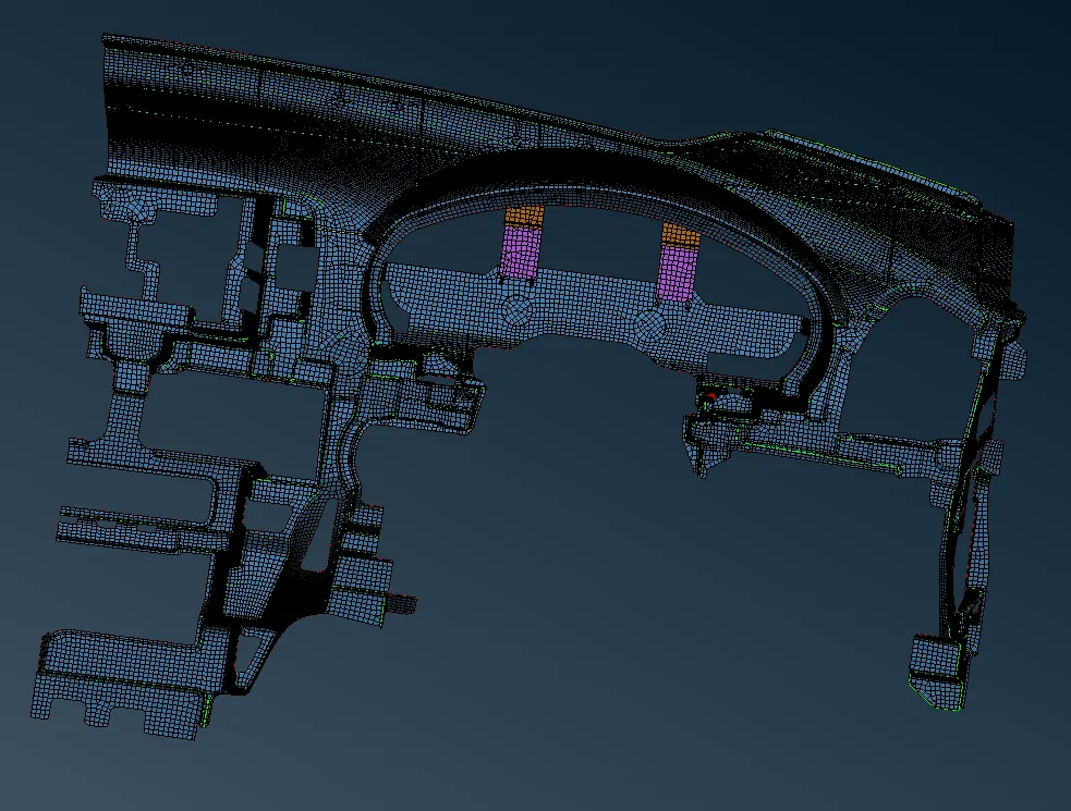
Below are some images to get the idea of the mesh employed in the model.
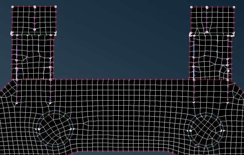
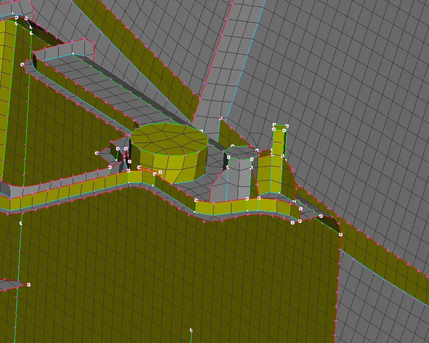
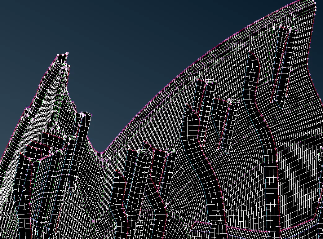
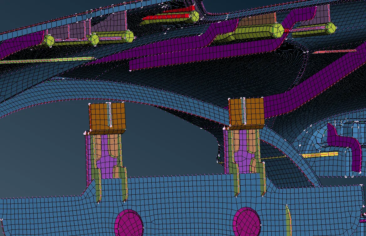
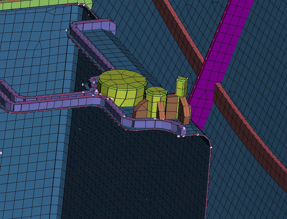
After completing meshing we can enable the Draw Shell as Solid option in the quality criteria presentation parameters. This is how the model looks then.
Learning Outcome: Practising this type of complex models is very interesting and midsurfacing can be achieved easily. Meshing and maintaining its flow on a large part like this is learned.
Conclusion: Carrying out midsurface for IP substrate is done accurately, though it was difficult as it has many intricate parts and features with different thickness. Meshing such part ensures good practice on ANSA midsurfacing tools and meshing tools.
Below is the link to download the meshed model of IP substrate.
https://drive.google.com/file/d/1kreDVmjqljihTbiO60hs7nUM3Y6OctgM/view?usp=sharing