Meshing of Rear Wheel Holder | Hypermesh | 2D meshing | Sheet metal
Objective: To mesh the given floor panel component with the given quality criteria.
Quality Criteria:
Target Element Length = 5mm
| S.N | Quality Criteria | Value |
| 1 | Aspect Ratio | 5 |
| 2 | Skewness | 45 |
| 3 | Warping | 15 |
| 4 | Taper | 0.5 |
| 5 | Min. Length | 2mm |
| 6 | Max. Length | 8mm |
| 7 | Min angle Quad | 45 |
| 8 | Max angle Quad | 135 |
| 9 | Min angle Tria | 20 |
| 10 | Max angle Tria | 120 |
| 10 | Tria % | 10 |
Procedure:
The given component is a floor panel which is used under the dickey of a car where a stepney fits in.
Below is the image of the model.
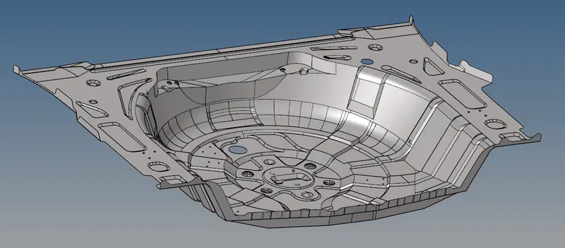
Thickness of the component is 0.75mm throughout, hence 2D meshing is preferred by taking midsurface.
For midsurfacing we can use manual method or auto method after cleaning the geometry.
On the midsurface, create mesh with the given quality criteria.
Assign thickness to the mesh.
1. Geometry cleanup:
The errors in the geomtery as shown in the images below are cleared by using tools in the Geometry deck.
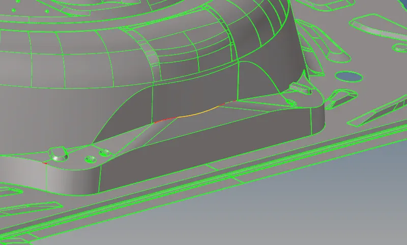
After getting clean geometry, we proceed for midsurface.
2. Midsurface extraction:
This is a simple geometry from thickness and features point of view. There no ribs or pads on the component and constant thickness over the entire component. Hence, automidsurface can be carried out easily on this component.
Under the Geometry deck, use midsurface>auto midsurface>offset option. This gives a proper midsurface.
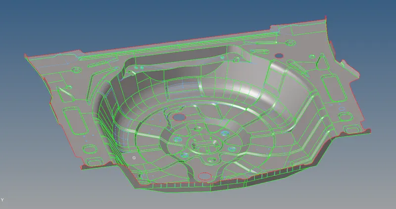
The obtained midsurface is also cleaned for obtaining proper mesh flow and no failure of elements.
Below image shows the midsurface of the component.
3. Meshing:
Once we are given the quality criteria, create a criteria file for ease of work.
Again, for meshing one can go manually by surface to surface or one shot mesh.
As this is not a complex component we can proceed with one shot mesh and remesh it for obtaining proper mesh flow and quality of the elements.
For the given quality this is the criteria specified.
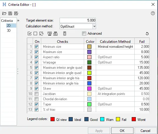
After obtaining one shot mesh there will be lot of tria elements which needs to be taken care of and eliminated as much as possible.
There should not be any trias on the curved surfaces and edges on the surface. This is mainly because the tria elements are stiffer than a quad element as it has only one plane and cant be bent. Hence, if trias are present on curves or any surface it gives less deformation than actual result.
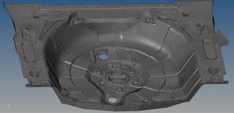
The final mesh looks as shown below image.
4. Thickness:
Assigning the thickness is one of the most important part for 2D meshing. A 2D mesh is created to reduce computaional cost and time and to simplify the solution. But there is need of defining the 3rd dimension to the software to carry out the calculations in that dimesnsion also.
We can assign the thickness by creating a property card for the component and assign a material and thickness to the card.
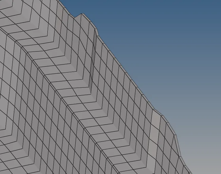
After assigning the thickness and visualizing it, this how the component looks.
Conclusion:
The given component, rear wheel holder(floor panel) is meshed with given quality criteria with zero failing elements.
The appropriate thickness of the component has been assigned to it.