Advanced Sheet Metal Design Using NX Cad Challenge_1_Casing Design
TITLE: Casing Design using NX Cad.
OBJECTIVE: Write a detailed report on Sheet Metal components with a good explanation of Sheet Metal modelling tools applied throughout the modelling. Also, attach the Final model Images (Min. 4 images) of the Sheet Metal Casing.
INTRODUCTION: Siemens NX Cad is designing software for advanced and complicated product design with ease. Straight and simple tools are available for drafting 2D and 3D models. Where different designing software needs different parameters and constraints to set up but here we are really free to design as a real-life product with advanced methodology.
Here we have to gain knowledge in Sheetmetal operation from basics to advance format. From designing a simple tab to contour flange, with various modelling features like three bend corner, dimple, flat pattern, etc.
DESIGN METHODOLOGY:
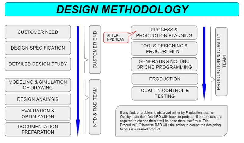
DESCRIPTION: To design a "Casing" we have used the 'Sheetmetal' operation. A brief designing description for a product is as follows:-
- First created a 'tab' on XY-Plane. And on the same plane, a new plane 'P' is created for further design.
- Then a 'Normal cutout' operation is performed with the required sketch profile.
- With the help of 'Bend,' a two side fold is done as a designed model.
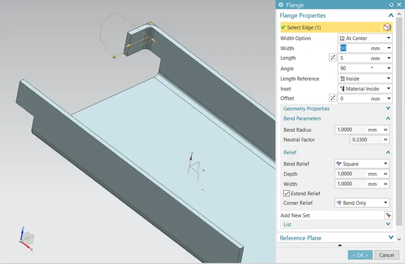
- After that 4 flat flanges are created on 4 bent corners of the model.
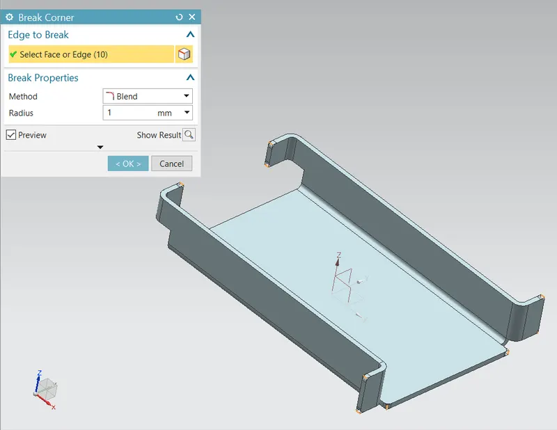
- All those corners generated on a model are curved-out as per parameters with help of the 'Break corner' operation.
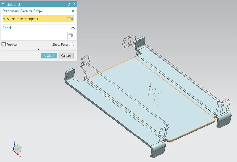
- Then proper 'unbend' is done to get a product for further modelling.
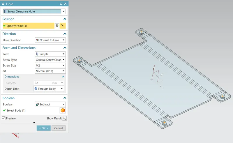
- Now on all 4 flat flanges 'Hole' is created on specified dimensions.
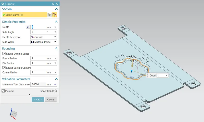
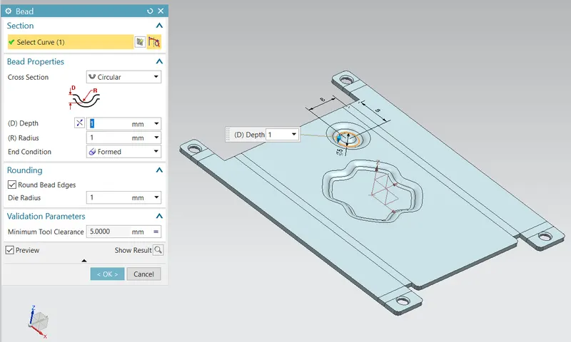
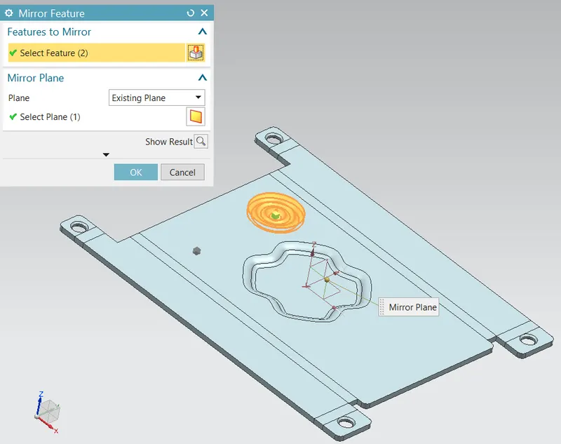
- A 'Dimple' is created on XY-Plane from orienting a sketched 'spline' by mirroring it as required for modelling. And along-side 'Bead' is also created in the same manner on the 4 corners of 'tab' by mirror operation.
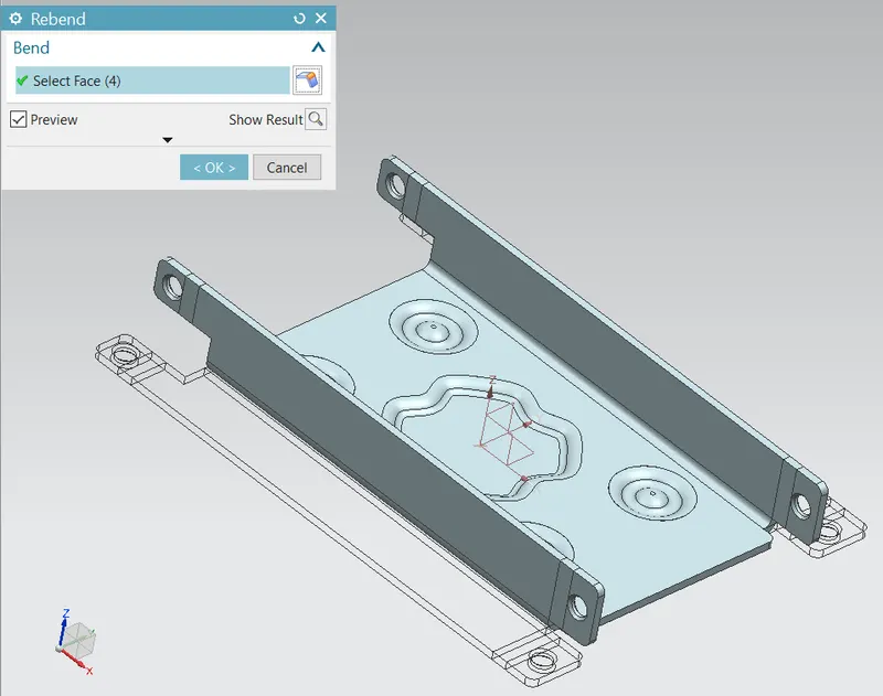
- Now 'Rebend' is done in a way exactly opposite to the way bending is performed to get the exact required shape of the product.
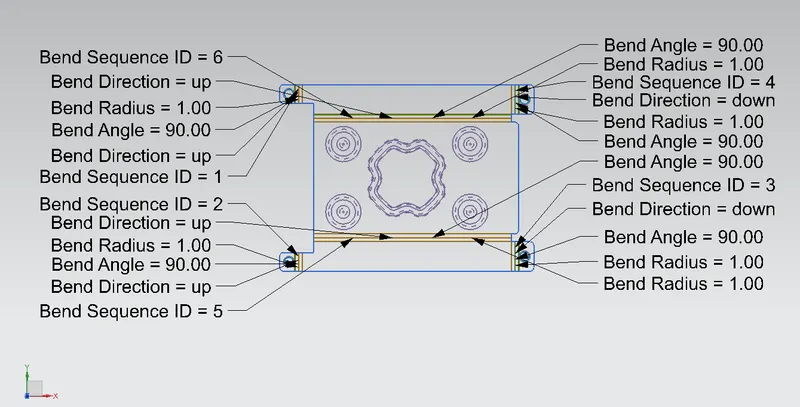
- At last in the same modelling part, 'Flat Pattern' is created. That 'flat pattern' can be viewed from 'Model view' located in the 'Part Navigator' folder. And that 'Flat pattern' contains a detailed specification for a drafted model.
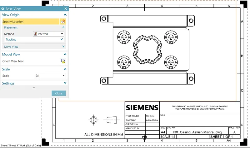
After all these modelling operations are over we creates an A4 drawing sheet of a 'Flat Pattern' in a "2:1" scale ratio with no text written over there.
Different tools used for creating 'Casing':
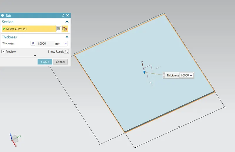
- TAB:- A flat sheet metal sheet is obtained here by default parameters(global parameters) and selection of sketch. A 'tab' is a cut-out from the raw material to further process as a final product with different operations on it.
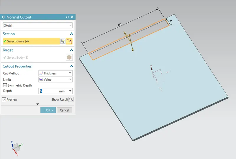
- NORMAL CUTOUT:- A sketch is drawn to be cut out from the sheet. In 'Normal cut-out' the cut is always perpendicular to the cutting surface or only tangent propagation cut occurs on the surface.
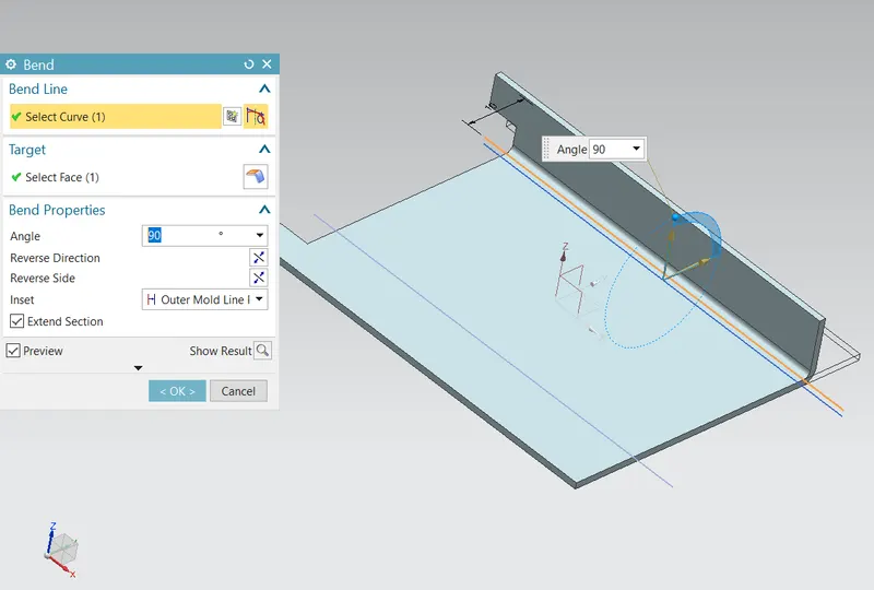
- BEND:- A bending line or profile is sketched and with the help of which bend is done in the required direction or axis.
- FLAT FLANGE:- An extended part of the existed component with various width options to be modified with the desired angle, bend radius, relief, length by selecting any edge of the component. 'Flanges' are the external or internal by-products that serve either to increase strength or for attachment with any other object.
- BREAK CORNER:- This operation is only used to create fillet or chamfer on the edges of the component.
- UNBEND:- Used to make straight or flat the sheet metal from a twisted or bent position to get it in a relaxed position for further modifications. Once the flat face is selected (to be fixed), then bent corners are selected to unbend.
- HOLE:- 'Hole' is the part of the component either to be removed or to be filled, it can be in any form (general form, drill size hole, screw clearance hole, etc). For creating a hole we just need to define a centre point. Rest features will be controlled by the working tab, hole type, dimension, fit type, depth limit, screw-type etc.
- DIMPLE:- 'Dimple' is a part of 'Sheetmetal forming operation' where it is done either to make the product look good or to increase its efficiency. A sketch is required for creating a dimple and then dimple properties & parameters are set.
- BEAD:- 'Bead'can be of different cross-sections like circular, v-shaped & u-shaped along with parameters like depth, radius, die radius, end condition and tool clearance.
- MIRROR FEATURE:- In 'Mirror' operation the feature, curve, plane, bodies, geometry can be copied along any symmetric axis, plane, reference plane or axis or geometry or bodies.
- REBEND:- This is a similar operation technique as of 'Unbend'. But here instead of creating a straight or flat product we change the flat product to the original shaped product but in reverse order, as done to 'unbend' the component.
- FLAT PATTERN:- 'Flat Pattern' operation is used to create a 2D pattern of the final component with all centrelines, bending curvature lines, flanges line, holes & their centres with detailed specifications.
- DRAFTING:- This is a general drawing sheet formation with a 2D drawing with proper representation as per scale.
DIFFERENT VIEWS OF MODEL:-
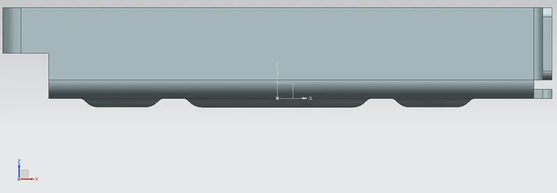
FRONT VIEW

TOP VIEW
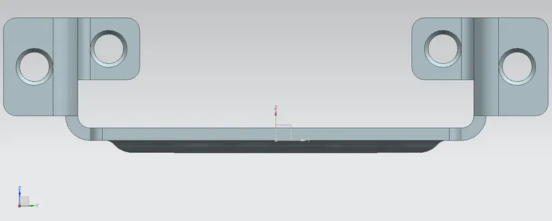
SIDE VIEW
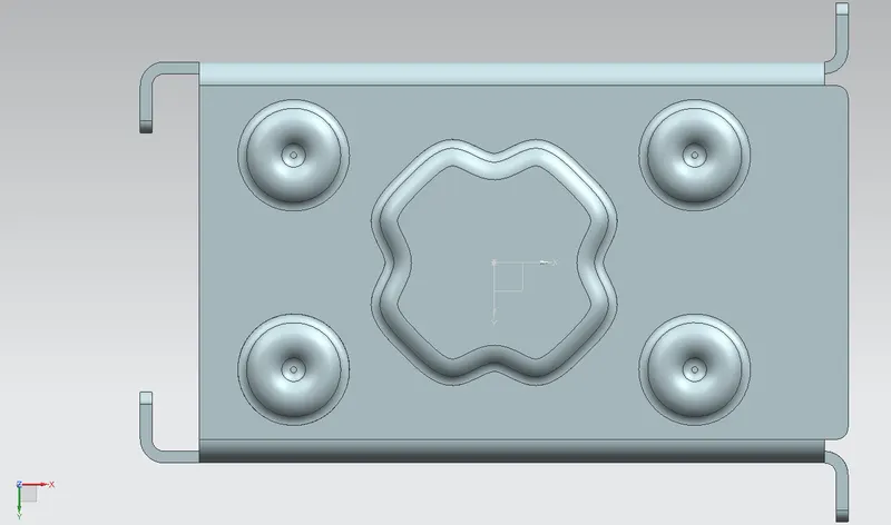
BOTTOM VIEW
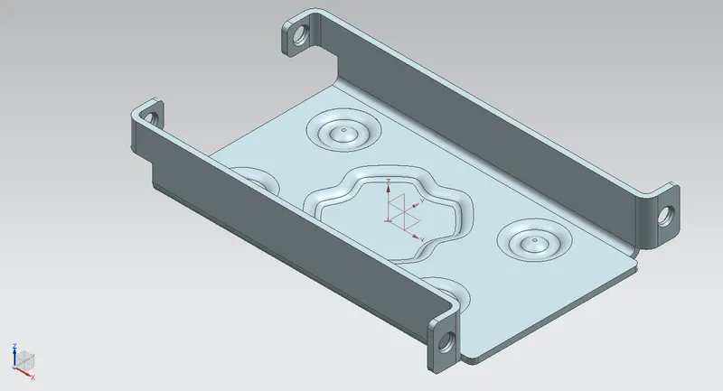
ISOMETRIC VIEW
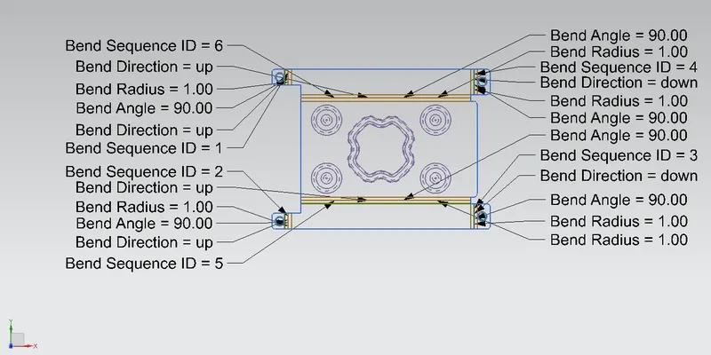
FLAT PATTERN VIEW
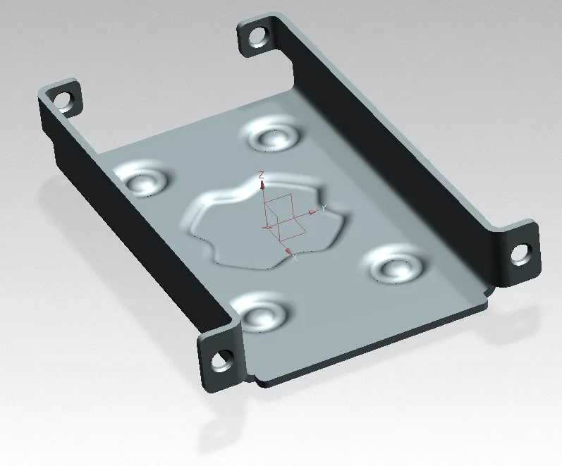
NORMAL RENDER LAYOUT
DRAWING SHEET:-
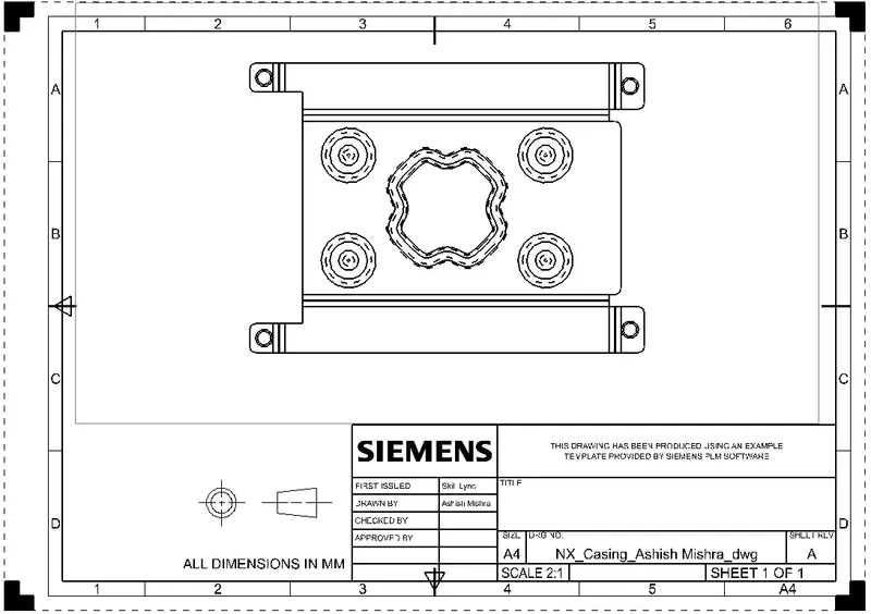
Drawing without any detailed parameters or specifications.
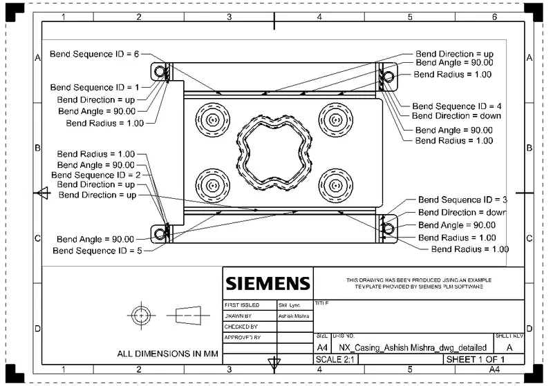
Drawing with all detailed parameters or specifications.
CONCLUSION:-
In this project, I have learnt some of the "Feature's" of 'Sheet Metal' to design 'Casing'. All these features include knowledge from Basic to Advanced level of drafting technique. All introductory 'Graphics User Interface' is learnt in this project work before starting any of the main designing parts. Different drafting tools are used here for drafting & modelling. The tools used in this project to create 'Casing' are tab, bend, normal cut-out, mirror, break-corner, bead, dimple, hole, unbend, rebend, flat pattern, drawing sheet. After this modelling & drafting of 'Casing' is completed, an A4 drawing sheet is created with as required parameters for designing.