Advanced Sheet Metal Design Using NX Cad Challenge_6_Bracket
TITLE: Creating Sheet Metal ("Bracket") using different techniques.
OBJECTIVE: Write a detailed report on Sheet Metal components with a good explanation of Sheet Metal modelling tools applied throughout the modelling. Also, attach the Final model Images (Min. 4 images) of the Sheet Metal Bracket.
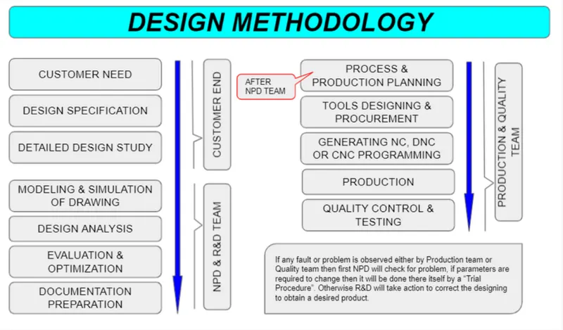
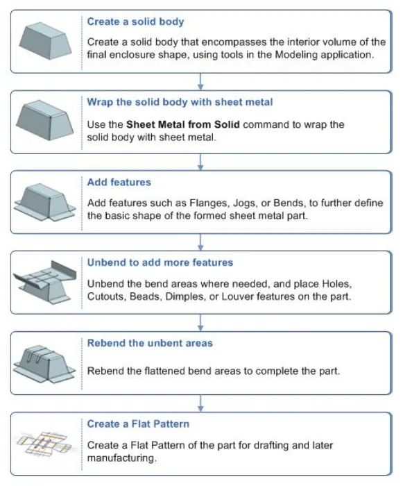
DESIGN METHODOLOGY :
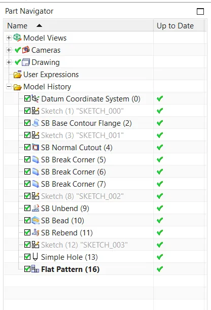
PART NAVIGATOR or FEATURE TREE:
DESCRIPTION :
Sketch:- This is a base step of every model but in some cases, a different approach will be required to create such drafts. One of the best examples is mentioned below, where the handy version of arc & lines are used. 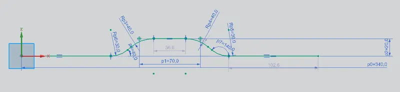
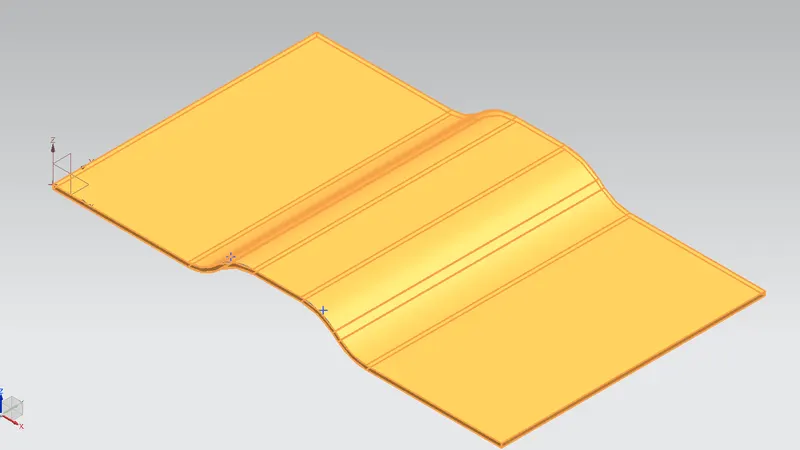
Contour Flange:- This type of flange are used where curves or splines are used to create a sketch on the base plane. Also while sweeping along the edge & vectors we do not face any error in this.
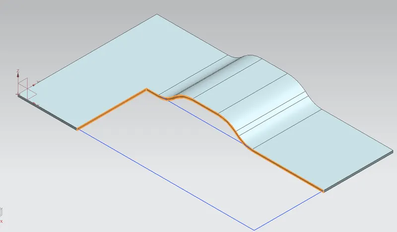
Normal Cut-out:- Use of this tool is very simple & easy. A sketch from the cutout is drawn and along the face or perpendicular to that, the features are used to trim the metal.
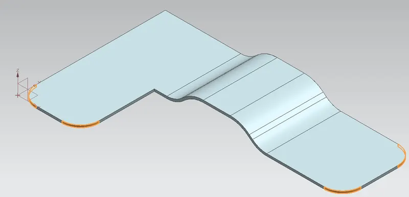
Break Corner:- Easy and handy tool to provide roundness or fillet to sheet-metal of any desired radius.
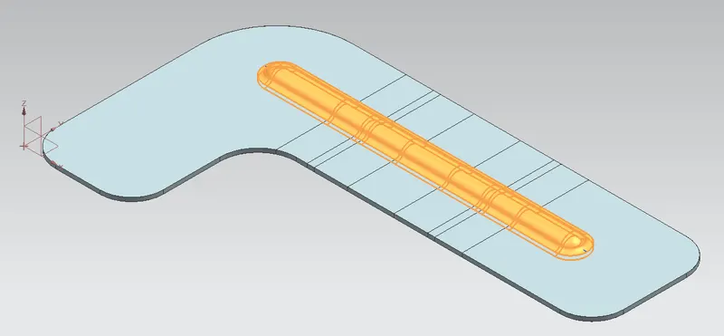
Bead:- 'Bead' can is of different cross-sections like circular, v-shaped & u-shaped along with parameters like depth, radius, die radius, end condition and tool clearance.
HOLE:- 'Hole' is the part of the component either to be removed or to be filled, it can be in any form (general form, drill size hole, screw clearance hole, etc). For creating a hole we just need to define a centre point. Rest features will be controlled by the working tab, hole type, dimension, fit type, depth limit, screw-type etc.
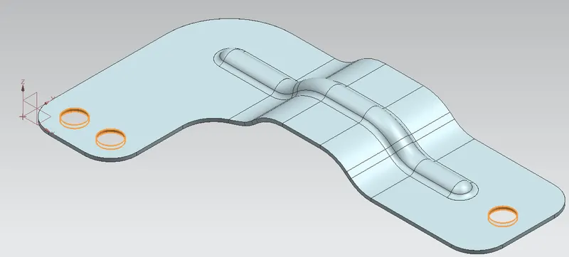
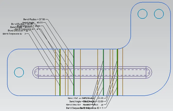
FLAT PATTERN:- 'Flat Pattern' operation is used to create a 2D pattern of the final component with all centrelines, bending curvature lines, flanges line, holes & their centres with detailed specifications.
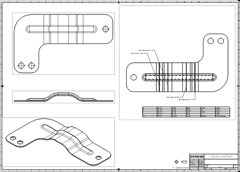
DRAFTING:- This is a general drawing sheet formation with a 2D drawing with proper representation as per scale.
DIFFERENT VIEWS:-
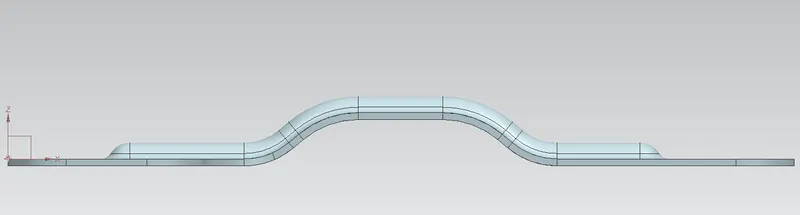
Front View
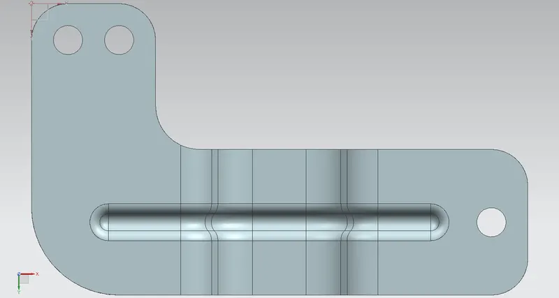
Bottom VIEW
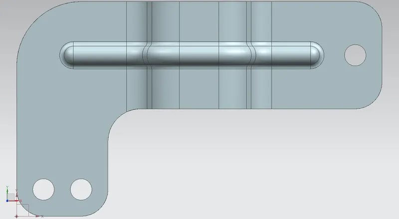
TOP VIEW'
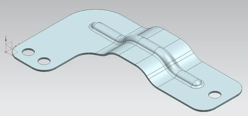
ISOMETRIC VIEW