Advanced Sheet Metal Design Using NX Cad Challenge_7_ Metal bracket-II
TITLE: Creating Sheet Metal ("Metal Bracket - II").
OBJECTIVE: Write a detailed report on Sheet Metal components with a good explanation of Sheet Metal modelling tools applied throughout the modelling. Also, attach the Final model Images (Min. 4 images) of the Sheet Metal Bracket.
INTRODUCTION: Here we will design 'Metal Bracket' using various tools and features from basic to advance manner.
Metal Bracket: Brackets are used either to hold or clamp two different parts at any specified angles (usually at 90° angle). Various cut-outs and other features will be created on it, not only to provide better grip between two surfaces but also to strengthen the bracket. The easy and best example is 'wall clamping of tv', 'L-angles to hold wooden plank'.
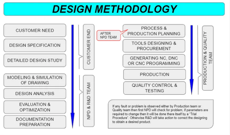
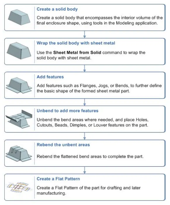
DESIGN METHODOLOGY :
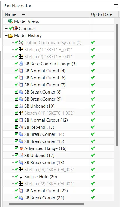
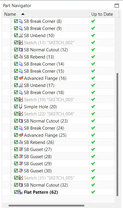
PART NAVIGATOR or FEATURE TREE:
DESCRIPTION :
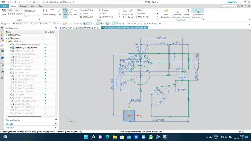
Sketch:- The sketch is the backbone of every designer. Varieties of tools are available to draft an item. According to the requirements lines, rectangles, spline, arc, circle, point, polygon, ellipse and other tools can be used to draft a product.
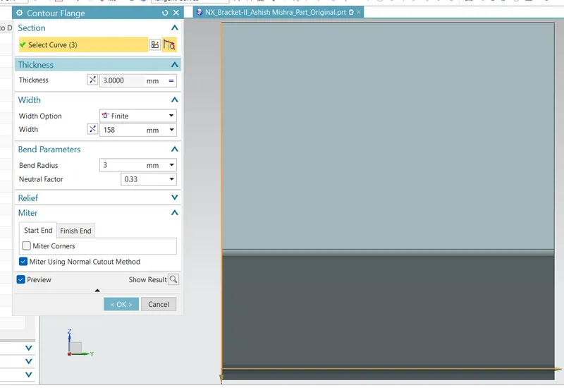
Contour Flange:- This tool is an extrude option in Sheetmetal, where using different curvatures in a chain develops a base to modify accordingly. Users can play here with thickness, width and bend radius wherever applicable.
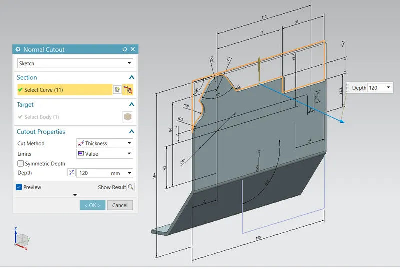
Normal Cutout:- Trim tool for featured items. Used to cut material along the defined sketch path with different cutout properties where we can modify method (define neutral axis), limit (define cutout section) & depth (depth of cut). The difficult task here is to define a trim sketch with no overlay.
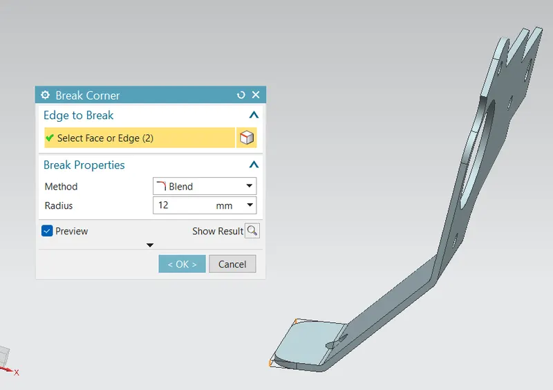
Break Corner:- Tool is used to provide fillet or chamfer to tab/flange/any other part of the material. Just have to define face or edge with break type and value of same.
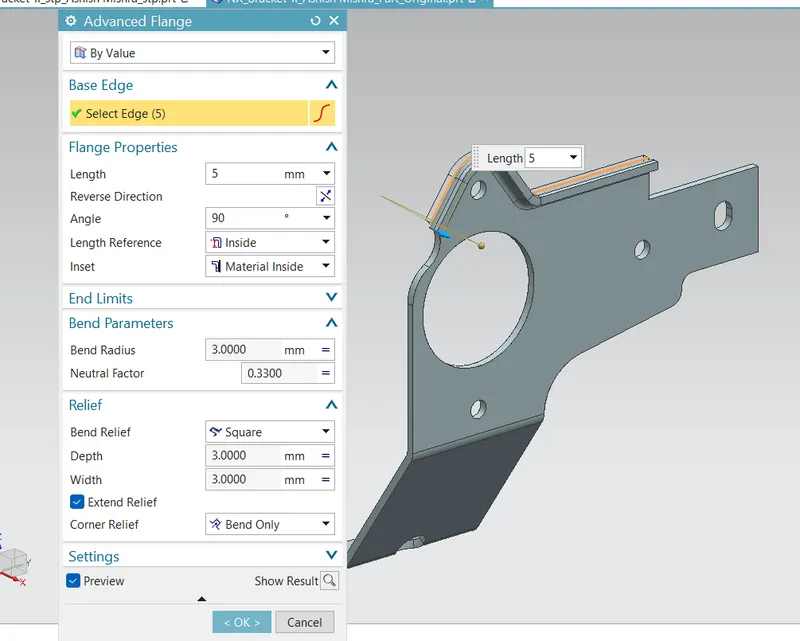
Advanced Flange:- A very helpful and extremely advanced tool to create smooth flange over the edge with a desired angle and length of the flange, also the flange material properties can also be modified with bend relief either as square or round or none along with depth & width.
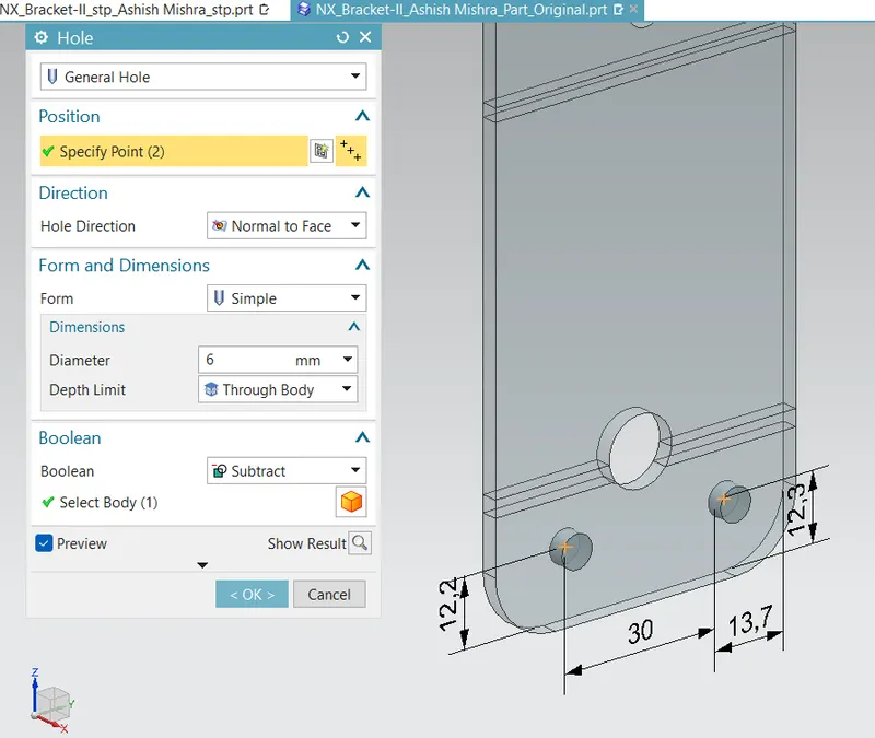
Simple Hole:- Point with specified dimensions is used to create a hole in the material. Hole type and directions can be specified with either to add material or subtract from the original one.
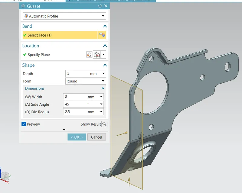
Gusset:- They are used to strengthen the bend are of any part. Gussets can be drawn either Automatically or can be defined by the user. Shape and dimensions for it can be altered according to design and strength to be given to part.
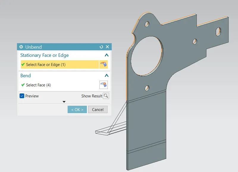
Unbend:- Used to temporary flat a material along the fixed or stationary face of the object and unbend along the curved face. This feature is basically used to modify the object without tempering predefined edits.
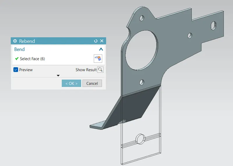
Rebend:- After editing is done on unbend area, the part needs to be in original shape, and that is done in exact reverse manner bend is done.
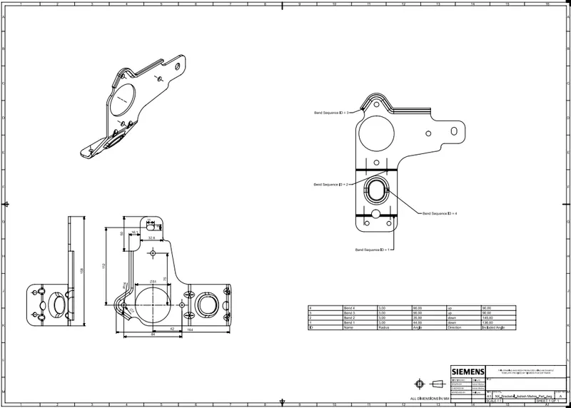
Drawing Sheet:- This is a general drawing sheet formation with a 2D drawing with proper representation as per scale.
DIFFERENT VIEWS:-
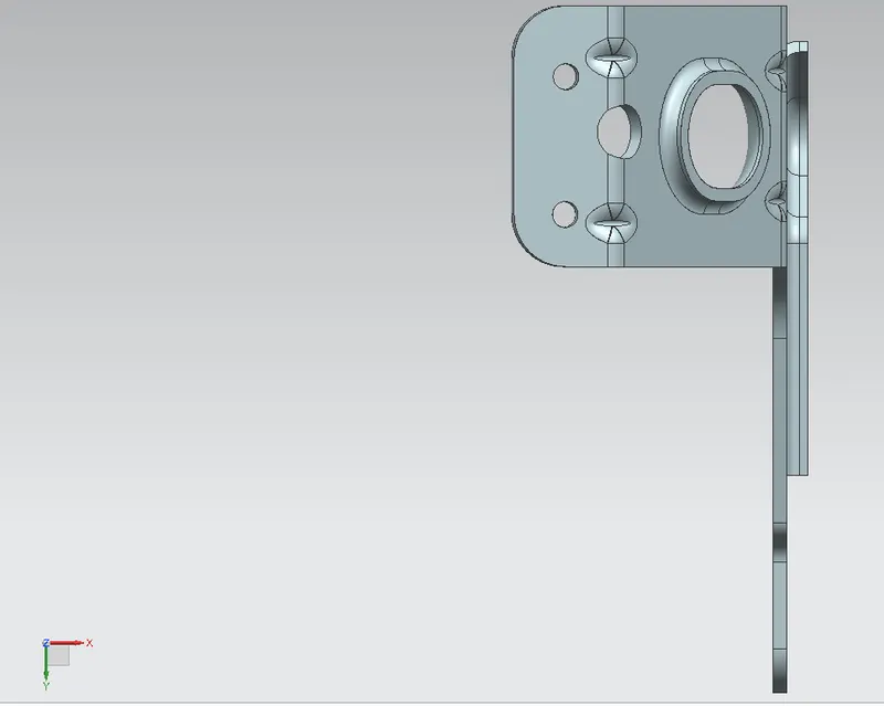
Bottom View
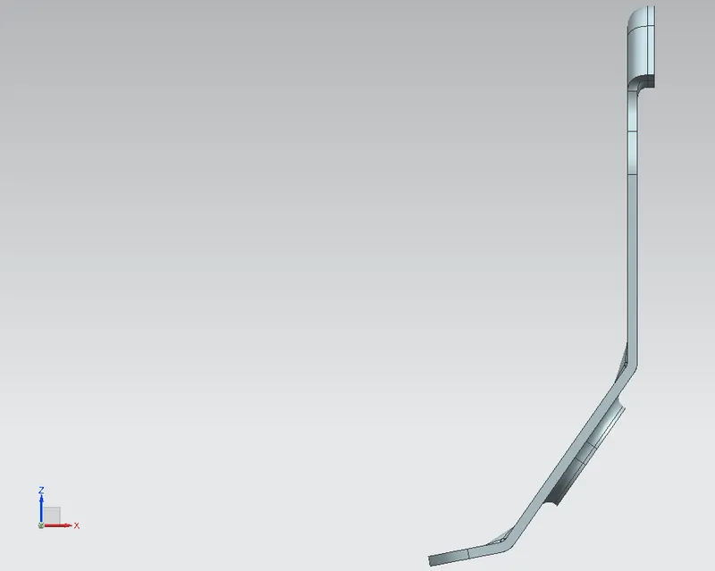
Side View
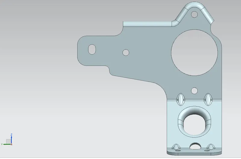
Front View
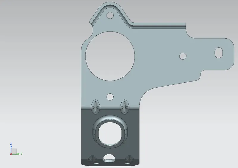
Back View
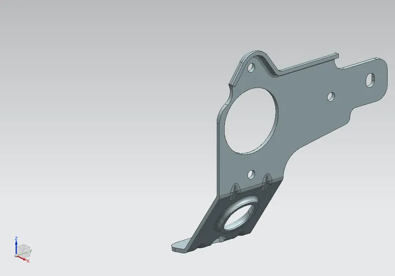
Isometric View
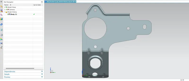
Bracket-II.stp file format view
Conclusion:-
The 'Metal Bracket - II' is a good part to learn different tools & features used to draft. The new feature 'Advanced Flange' practical application allowed me to learn more about it. Along with different new techniques used in various old features provides great knowledge.