Courses by Software
Courses by Semester
Courses by Domain
Tool-focused Courses
Machine learning
POPULAR COURSES
Success Stories
Barrel Cam & Follower Finite Element Analysis using ANSYS Workbench
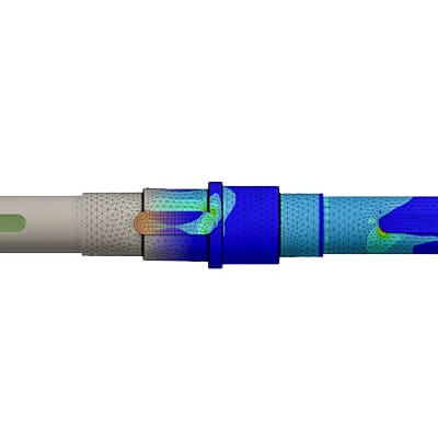
Objectives: To analyse barrel cam and follower for stress, strain analysis. Geometrical Design: For this analysis we have geometry which contains three major parts named as Barrel, Barrel Cam and Cam Follower. This is how geometry looks like; Material Properties: Structural Steel is used for whole assembly here,…
Vishal Joshi
updated on 26 Apr 2020
- Objectives: To analyse barrel cam and follower for stress, strain analysis.
- Geometrical Design:
For this analysis we have geometry which contains three major parts named as Barrel, Barrel Cam and Cam Follower.
This is how geometry looks like;

- Material Properties:
Structural Steel is used for whole assembly here, here its Mechanical Properties.

- Problem Statement:
Barrel Cam & Follower assembly will be applied with constraints and applied with rotational motion to capture various aspects such a Deformation, Strain & Stress.
- Mesh Criterion:
Type of Elements: Automatic Meshing (Tet & Hex Elements)
Size of Elements: 8.9806 mm (Default)
Mesh Refinement: 3 mm (Face Sizing)
Default Mesh:

Face Sizing:

- Boundary Condition:
We will look for only Cam and Follower Parts so other part’s stiffness behaviour switched from
Flexible to Rigid.
Stiffness Behaviour:

Contacts:
One Fixed Joint applied to Barrel, One Revolute Joint applied to Barrel Cam and One Translational Joint applied to Cam Follower.

- Loading and Analysis Setting:
Project carried out with 9 Steps, Large Deflection kept ON & all other parameters kept default. Time Steps are as follows;
Initial Time Step: 0.1 s
Minimum Time Step: 0.05 s
Maximum Time Step: 0.2 s
Maximum Time Step: 0.3 s (Step 2 to 9)
Analysis Settings 1:

Analysis Settings 2:

Loading:
For Loading Revolute Joint applied to Barrel Cam, in each step it is rotated by 30 Degrees.

- Post Processing:
Whole assembly is analysed for 3 cases, in 1st Case Contacts kept as frictionless, in 2nd case friction co-efficient set to 0.1 & for 3rd case co-efficient set 0.2.
Case 1 (Frictionless)
Total Deformation

Equivalent Elastic Strain

Equivalent Stress

Directional Acceleration

Directional Velocity

Case 2 (Friction Co-efficient = 0.1)

Total Deformation

Equivalent Elastic Strain

Equivalent Stress

Directional Acceleration

Directional Velocity

Case 3 (Friction Co-efficient = 0.2)

Total Deformation

Equivalent Elastic Strain

Equivalent Stress

Directional Acceleration

Directional Velocity

Post Process Results summary;

Click here to see Animation of this Project;
Barrel Cam & Follower FEA || ANSYS Workbench
- Results and Conclusion:
1) Total Deformation values are same in all three cases.
2) Equivalent Elastic Strain values are nearly similar in all cases except case 3, but difference is negligible.
3) There is drastic change in Equivalent Stress values in case 3 as the co efficient of friction set to 0.2
4) Due to C/F 0.2 there is change in Acceleration values in case 3 as well.
5) Similar to Acceleration, same kind of values achieved in Velocity parameters.
We can see that when there is no friction between the Barrel Cam & Follower, because of that the Stress & Strain values are low, when we increase the C/F to 0.1 there is sudden change in Stress due to presence of friction. When C/F set to 0.2 there is drastic change in values of each parameters. The Max. Stress values are clicking at 12406 Mpa. Due to presence of friction acceleration increases and velocity decreases (mainly Case 3) as the materials are taking more energy, due to that heat also gets generated in component. Various types of Contact and presence of Friction are crucial in this kind of FEA problems.
Leave a comment
Thanks for choosing to leave a comment. Please keep in mind that all the comments are moderated as per our comment policy, and your email will not be published for privacy reasons. Please leave a personal & meaningful conversation.
Other comments...
Be the first to add a comment
Read more Projects by Vishal Joshi (18)
Thermo Coupled Structural & Modal Analysis of a Horizontal Pressure Vessel with using ANSYS Workbench
Objectives: To Simulate Pressure Vessel for Thermo Coupled Structural & Modal Analysis Geometrical Design: We have an ASME Standard Dimensions of a Pressure Vessel so we made its 3D Model using Autodesk Inventor. Here are the Dimensions of the Pressure Vessel. This is the 3D Model of Pressure Vessel.…
28 Apr 2020 02:07 PM IST
Explicit Dynamic Analysis of Bullet Penetrating into Bucket using ANSYS Workbench
Objectives: To perform explicit analysis in bullet penetrating bucket challenge Geometrical Design: For this analysis we have a 3D Geometry of Bullet and Bucket, this is how model looks like. Material Properties: In this analysis 3 different materials will be used for bucket and for bullet only structural…
26 Apr 2020 11:04 AM IST
Barrel Cam & Follower Finite Element Analysis using ANSYS Workbench
Objectives: To analyse barrel cam and follower for stress, strain analysis. Geometrical Design: For this analysis we have geometry which contains three major parts named as Barrel, Barrel Cam and Cam Follower. This is how geometry looks like; Material Properties: Structural Steel is used for whole assembly here,…
26 Apr 2020 11:04 AM IST
Worm & Gear Finite Element Analysis (Transient Structural) using ANSYS Workbench
Objectives: To analyze Worm and Gear Assembly for Stress Analysis. Geometrical Design: For this project we have two parts in assembly named as Worm & Gear. This is how full geometry looks like, For the sake of FE Analysis we will look for stress only in half portion of gear, this will lead to less…
26 Apr 2020 11:04 AM IST
Related Courses


Skill-Lync offers industry relevant advanced engineering courses for engineering students by partnering with industry experts.
Our Company
4th Floor, BLOCK-B, Velachery - Tambaram Main Rd, Ram Nagar South, Madipakkam, Chennai, Tamil Nadu 600042.
Top Individual Courses
Top PG Programs
Skill-Lync Plus
Trending Blogs
© 2025 Skill-Lync Inc. All Rights Reserved.


