Wiring harness design in CATIA V5 - 3D modeling Week 4 Challenge
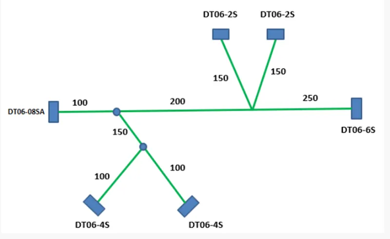
Route the following harness layout in Electrical workbench
OBJECTIVE:- Route the following harness layout in Electrical workbench. Make assumption for harness bundle diameters. Use Following connectors as shown in layout diagram.
Add protective covering on all branches connected to DT06-2S & DT06-4S connectors. Keep end extremity at 30mm (from connectors end)
Download connector 3D data from www.te.com
- DT06-4S
- DT06-6S
- DT06-2S
- DT06-08SA
DESIGN & ROUTING METHODOLOGY
- Download the Connectors 3D data from te.com
- Open the downloaded Connectors in Part Design workbench of Catia and Save as .CATPart
- Open each Connector and Create
- Connector Connection Point
- Bundle Entry Point
- Axis system on Connector Connection Point and Align the Y-Axis in Mating direction & X-Axis in the direction of Lock.
- Open each connector in Electrical Part Design workbench & Define Electrical properties.
- Click on Define Connector Symbol and then select the part.
- Click on Define Bundle Connection Point Symbol and fill the opened dialogue box.
- Click on Define Connector Connection Point Symbol and fill the opened dialogue box.
- Save the Part as Electrical Part.
- Create one Product file in Assembly design workbench as Wiring Harness Context Assembly
- Create another Product file in Assembly design workbench as Geometric Bundle under Wiring Harness Context Assembly
- Add all connectors under the Geometric Bundle in Assembly design workbench.
- Place all the connectors at desired locations as per given picture using Manipulation, Snap & Smart Move option.
- Now open the Geometric Bundle Assembly in Electrical Harness Assembly workbench.
- Click on Geometrical Bundle Symbol and select Geometric Bundle Assembly to defile Geometric Bundle Assembly as Electrical.
- Now Click on Multi-branchable Symbol and fill the opened dialogue box.
- Bundle Diameter
- Bundle Bend Radius ( Ratio must be > 1.4 )
- Build Mode As slack
- Now Click on Route definition
- Select DT06-08SA Connector and then DT06-6S connector and click Ok.
- Now click on Add branch Point Symbol and select the created bundle.
- Click on length and enter 100 and click ok.
- Now repeat last two steps to complete the given harness routing.
Harness Assembly Steps
Step-1 Download the Connectors 3D data from www.te.com
Step-2 Open the downloaded Connectors in Part Design workbench of Catia and Save as .CATPart
Step-3 Create one point on mating surface of Connector & rename it to Connector Connection Point.
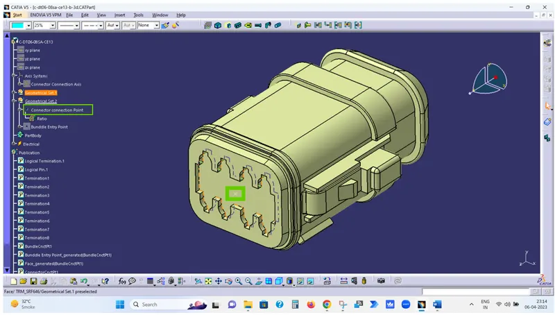
Step-4 Create one point on Bundle Entry surface of Connector & rename it to Bundle Entry Point.
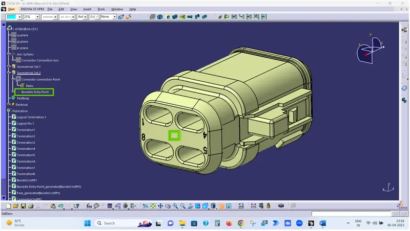
Step-5 Create Axis system on Connector Connection Point and Align the Y-Axis in Mating direction & X-Axis in the direction of Lock.
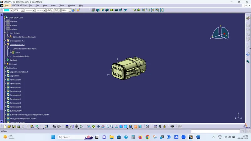
Step-6 Now open the Electrical Part Design workbench of Catia & Click on Define Connector Symbol and then select the part.
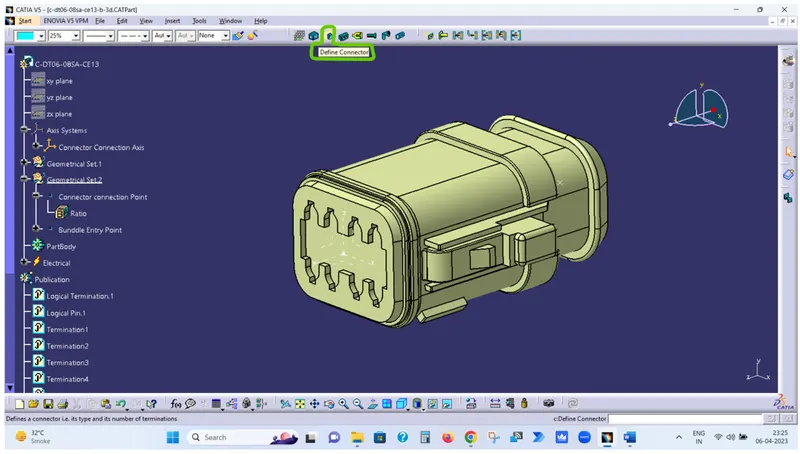
Step-7 Now click on Define Bundle Connection Point Symbol and fill the opened dialogue box.
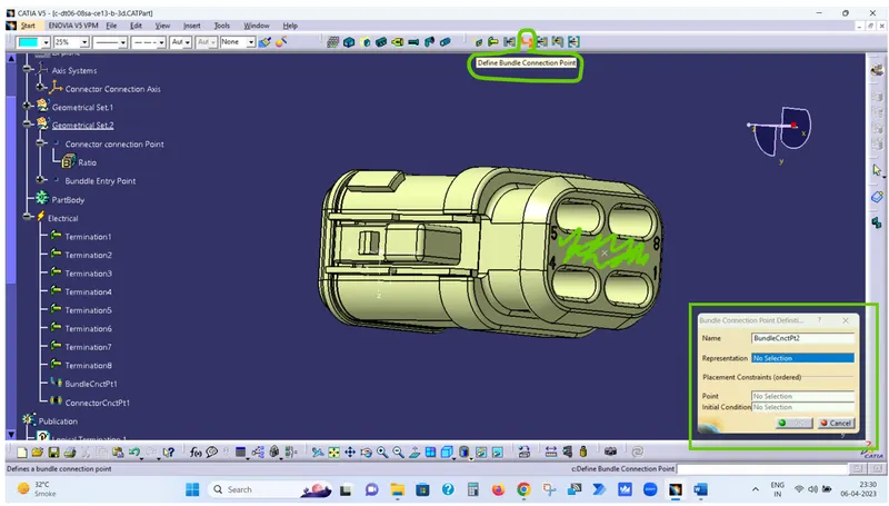
In Representation – Select the Green Highlighted Surface
In Point – Select the Bundle Entry Point
In Initial Conditions – Select the Green Highlighted Surface
Step-8 Now click on Define Connector Connection Point Symbol and fill the opened dialogue box
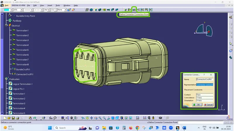
In Representation – Select the Connector Connection Point
In Contact – Select the Green Highlighted Surface
In Coincidence – Select the Y-Axis
In Orientation – Select the X-Axis
Step-8 Save the Part as Electrical Part.
Step-9 Repeat same Steps for all Connectors & save the as Electrical Part.
Step-10 Create one Product file in Assembly design workbench as Wiring Harness Context Assembly
Step-11 Create another Product file in Assembly design workbench as Geometric Bundle under Wiring Harness Context Assembly
Step-12 Add all connectors under the Geometric Bundle in Assembly design workbench.
Step-13 Place all the connectors at desired locations as per given picture using Manipulation, Snap & Smart Move option.
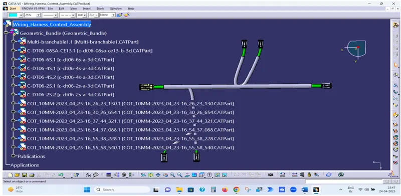
Step-14 Now open the Geometric Bundle Assembly in Electrical Harness Assembly workbench.
Step-15 Click on Geometrical Bundle Symbol and select Geometric Bundle Assembly to defile Geometric Bundle Assembly as Electrical.
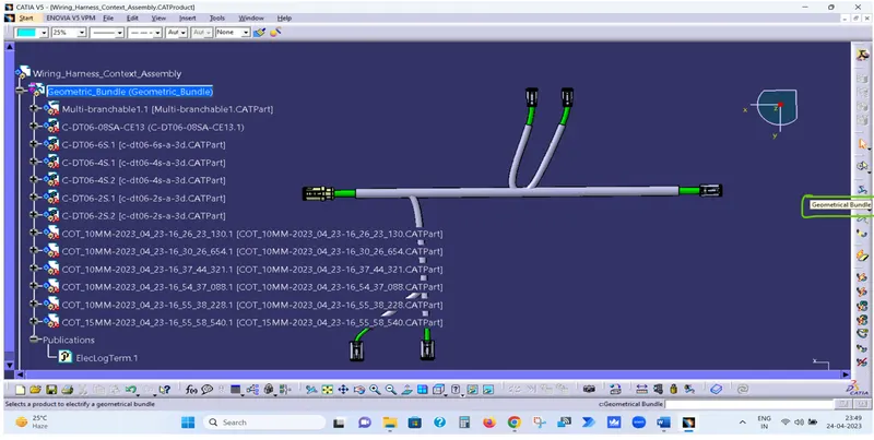
Step-16 Now Click on Multi-branchable Symbol and fill the opened dialogue box.
- Bundle Diameter
- Bundle Bend Radius ( Ratio must be > 1.4 )
- Build Mode As slack
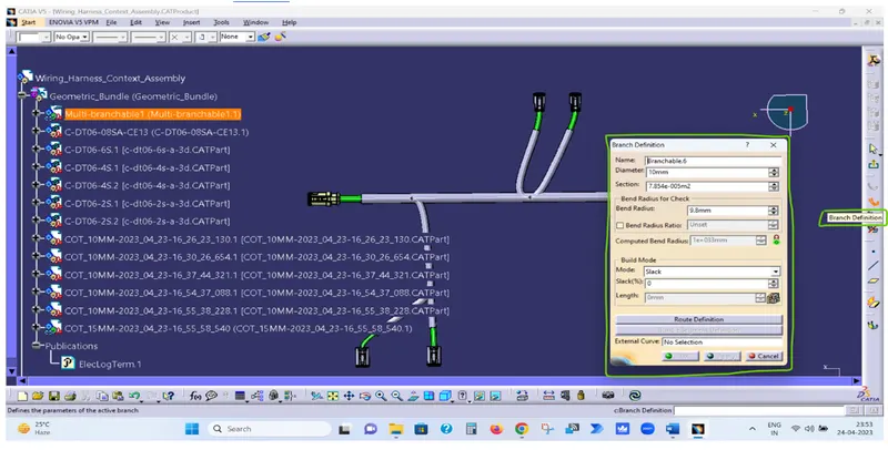
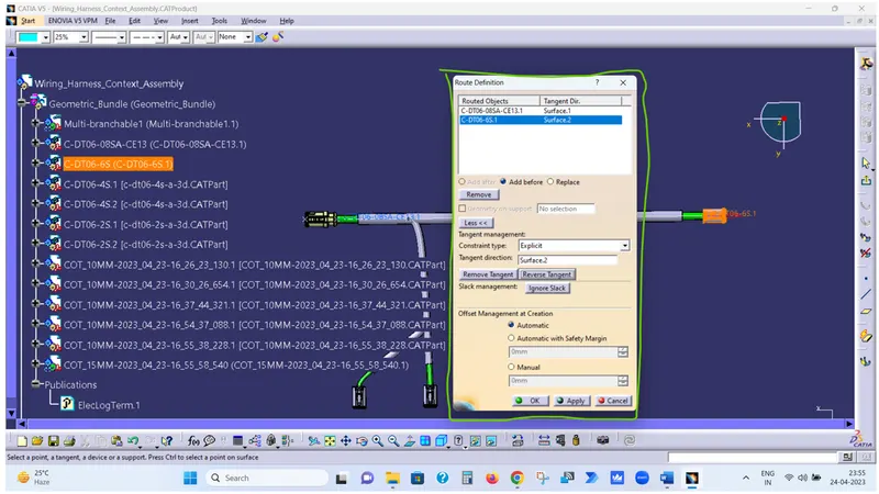
Step-17 Now Click on Route definition
- Select DT06-08SA Connector and then DT06-6S connector and click Ok.
- Now click on Add branch Point Symbol and select the created bundle.
- Click on length and enter 100 and click ok.
Step-18 Now repeat last two steps to complete the given harness routing.
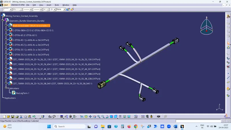
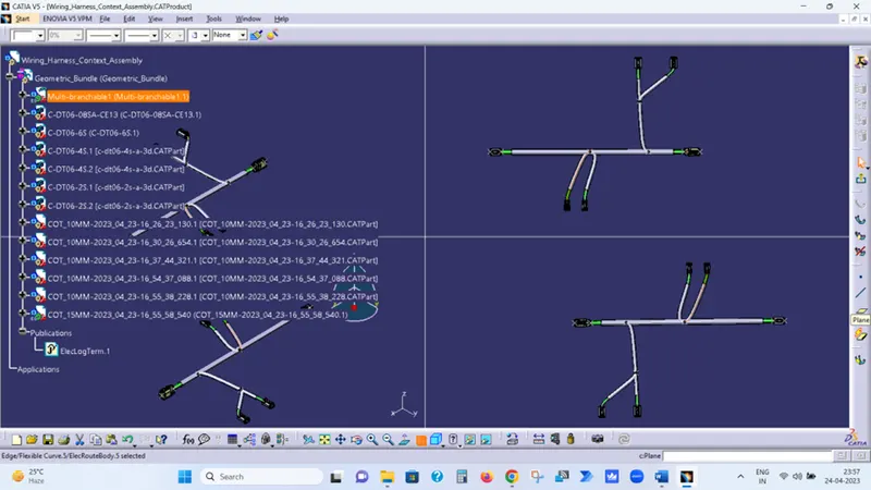
Wiring Harness Assembly is Completed as per Given Picture