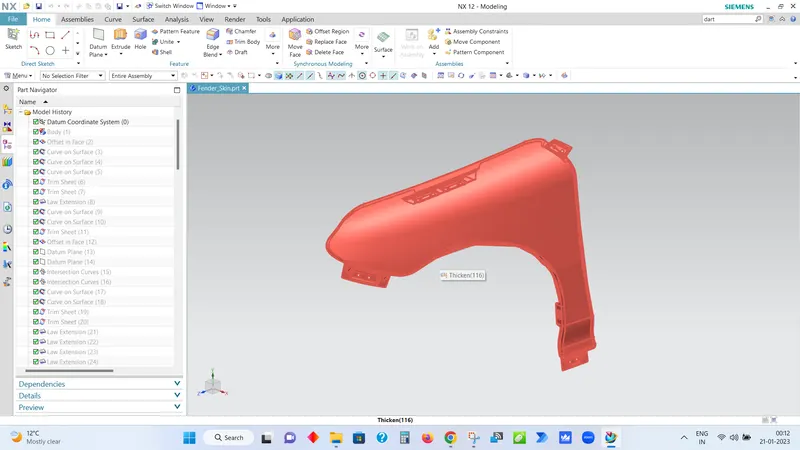
Fender Design
Fender
It is the American English term for the part of an automobile, motorcycle or other vehicle body that frames a wheel well (the fender underside). Its primary purpose is to prevent sand, mud, rocks, liquids, and other road spray from being thrown into the air by the rotating tire. Fenders are typically rigid and can be damaged by contact with the road surface.
Sticky materials, such as mud, may adhere to the smooth outer tire surface, while smooth loose objects, such as stones, can become temporarily embedded in the tread grooves as the tire rolls over the ground. These materials can be ejected from the surface of the tire at high velocity as the tire imparts kinetic energy to the attached objects. For a vehicle moving forward, the top of the tire is rotating upward and forward, and can throw objects into the air at other vehicles or pedestrians in front of the vehicle.
The fender's openings for the wheel wells tend to be much larger than the diameter of the tire, because they do not move with the tire suspension and consequently must be large enough to allow the full range of tire motion on the suspension without touching the interior of the wheel well. The streamlined 1949 Nash 600 and Ambassador design was first to feature fenders that enclosed the front wheels. More elaborate designs include fender skirts for enclosing the outside edge of the wheel well, and stylized pontoon fenders for exposed fenders.
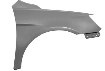
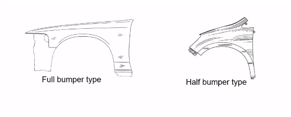
Type of Fender
- Full Bumper Type
- Half Bumper type
Fender Mountings
There are 5 mounting points in a fender
- Body
- A Piller
- Sill
- Cowl
- Drip
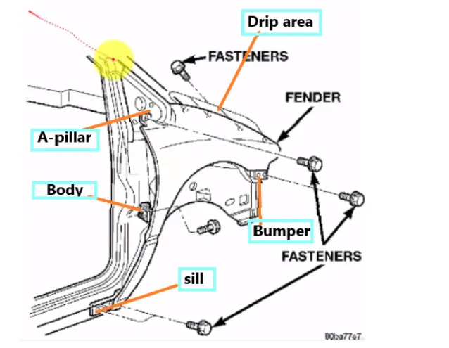
- For all 5 mounting points Festener holes must have atleast 5 mm of Flat area for proper fitment.
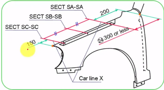
- Drip Area must be 150mm from head lamp & 200~300m from A Piller. as shown in Figure.
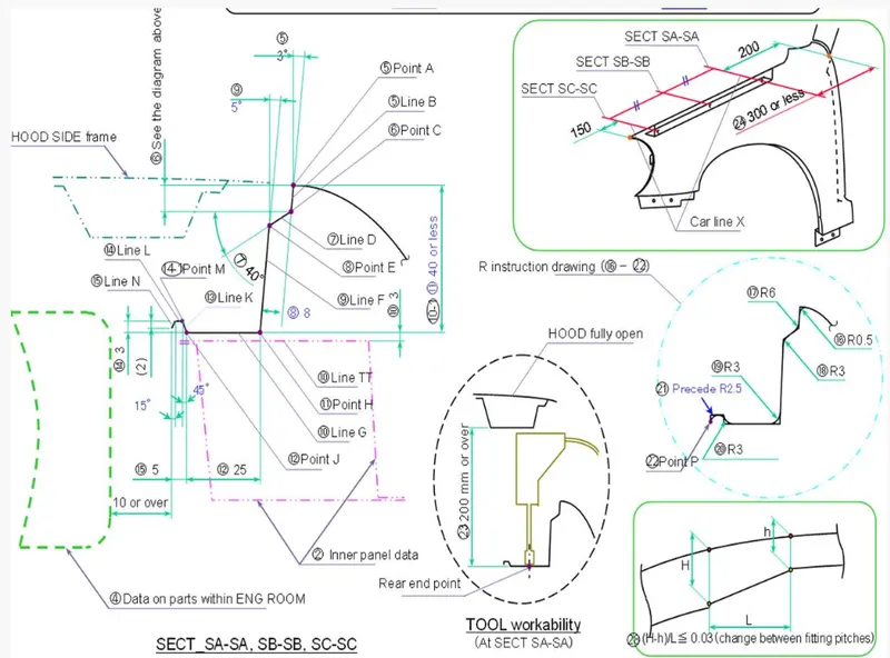
- Max depth of drip area should be <40mm to avoid spring back effect and for ease of manufacturing .
- For drip base flange , minimum draft of 3 degrees must be given to compensate for spring back and for modification if needed .
- An offset of 8mm should be given for vertical flange for hiding the visibility from outside .
- Clearance must be given to drip base area to ensure tool workability.
- Fillets should be made at all corners for ensuring manufacturability and safety.
- Embosses should be created at mounting points to improve strength .
Fender Wheel Arch Regulation
Wheel Arch is the semi-circular part of the fender positioned above the wheel of the vehicle. The design of Wheel arch of a fender should be such that it must shield wheels and protect both passengers' compartment and pedestrians from projection of water, mud and stones. The wheel Arch area of the fender is usually designed as a cover or sheild over the tyre along its perimeter to stop any debris or stones, dirt, sand, snow etc. from getting thrown into the vehicle/ BIW area as well as outside the vehicle and onto other vehicles or pedestrians on the road. For the vehicle to has its use permit in different countries, the wheel arch of fenders must be compliant with the standards and regulations set by the respective countries.
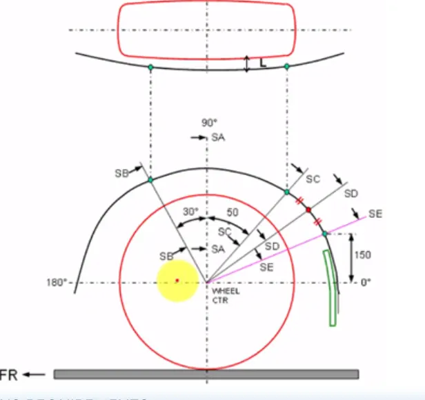
The European regulation requires a pre determined clearance or a minimum distance of 10mm. to be maintained between the Fender (Front Quarter Panel) and the respective tyre at particular points(5 points/Sections to be exact) along the tyre profile as shown below
By using the European regulation the wheel arc area for the given styling surface will be calculated as below
- A horizontal and vertical Axis is drawn from the centre of the wheel.
- The vertical axis intersection point is labelled as SA.
- Similar references are drawn at 30 degree forward and 50 degree rearward of the section SA and are named SB and SC respectively.
- A line of 150mm is drawn perpendicular to the horizontal axis and the normal from that point on the fender gives us SE.
- The midpoint of the arc cut by the sections SC and SE results in a new section SD.
- The value of 'L' at each section and the value of 'a' are found out to determine whether the fender satisfies the European standards as shown below.
Given master section for drip Area
Drip Mounting Point
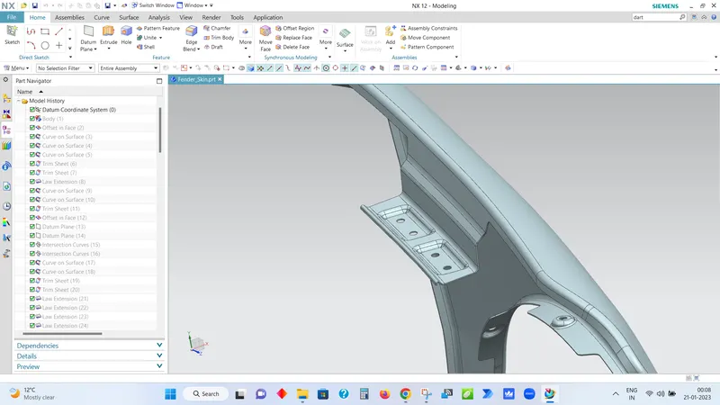
Sill Mounting Point
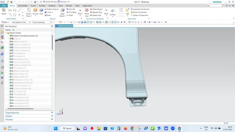
Bumper Mounting Point
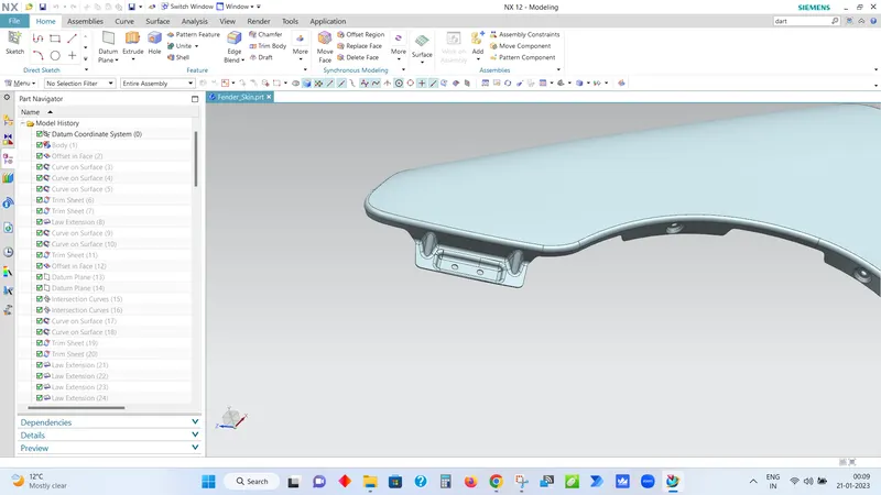
Baffle(Splash) Mounting Point
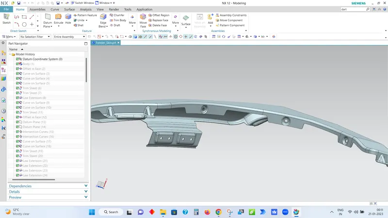
A-Pillar Mounting Point
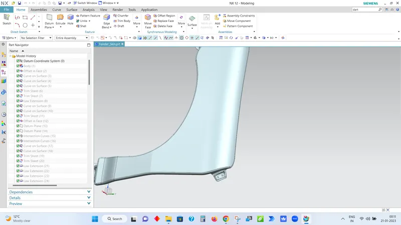
Fender