Week 8 - Challenge 2 - Switch Bezel Design
Switch Bezel Plastic component
Creating Switch Bezel Plastic Component from Given Class A Surface.
Tooling Axis
Tooling Axis is the direction in which mold opens.
if there is very big flat Surface or hole in the surface, Direction Normal to big flat surface or hole is generally tooling axis direction as holes must be clear in main tooling to avoid side core.
To get the proper tooling axis first create one Dummy tooling Axis & then analyse the part in all three directions.
then create intersection curve and create line on the surfaces which may causea trouble in that tooling axis direction then create Bisecting line, repeat the process in other directions also & create the second bisecting line with the bisecting line of three direction to get the main Tooling Asix.
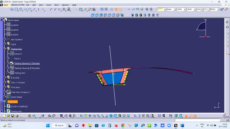
Screenshots of the Draft analysis report for both the given Class-A surface and the final plastic component
Draft Analysis Class-A surface
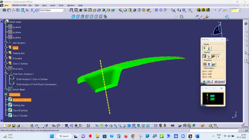
The above figure shows a draft of 2 degree is enough for easy ejection of part from the mould or tool.
- Green Colour represent Positive Draft.
- Blue Colour represent Negative Draft.
- Red Colour represent Zero Draft.
As we know 3 degree draft is most desirable, so after increasing the draft from 2 to 3 degree following result is obtained as shown in fig.
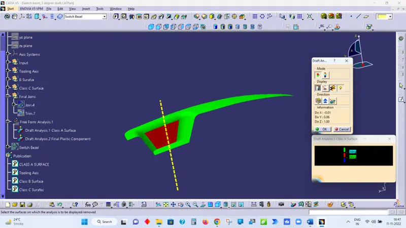
The green colour shows, the surface is having 3 or more than 3 degree draft. The red colour shows, the surface is having draft angle between 0 to 3 degree.
Draft Analysis final plastic component
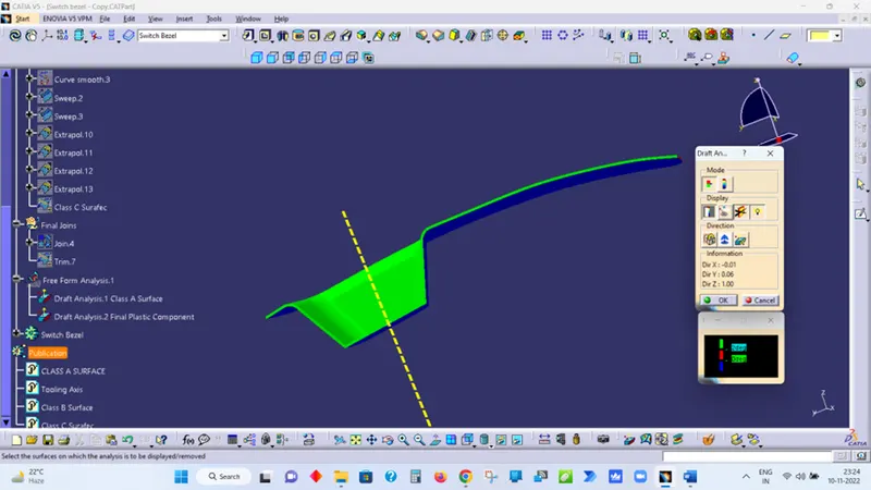
The above figure shows a draft of 2 degree is enough for easy ejection of part from the mould or tool.
- Green Colour represent Positive Draft.
- Blue Colour represent Negative Draft.
- Red Colour represent Zero Draft.
As we know 3 degree draft is most desirable, so after increasing the draft from 2 to 3 degree following result is obtained as shown in fig.
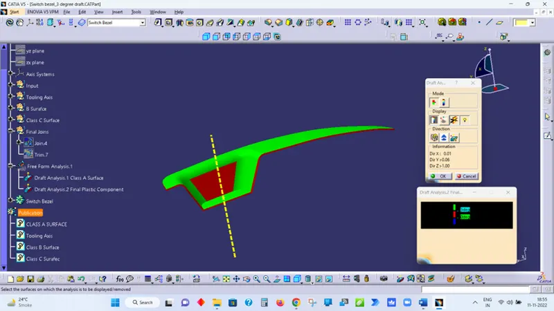
The green colour shows, the surface is having 3 or more than 3 degree draft. The red colour shows, the surface is having draft angle between 0 to 3 degree.
Screenshots of the solid model with the proper color code of the draft angle in various orientations (Isometric, Front, Side, and Top View)
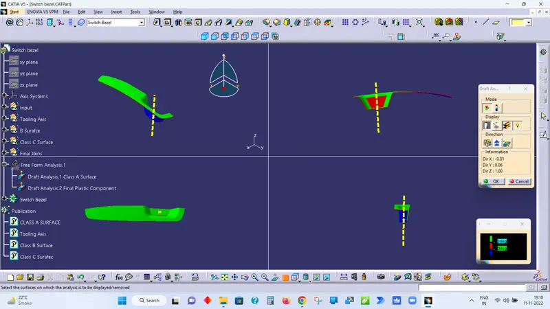
Draft Analysis Report Attached.