Wiring harness design in CATIA V5 - 3D modeling Week 5 & 6 Challenge
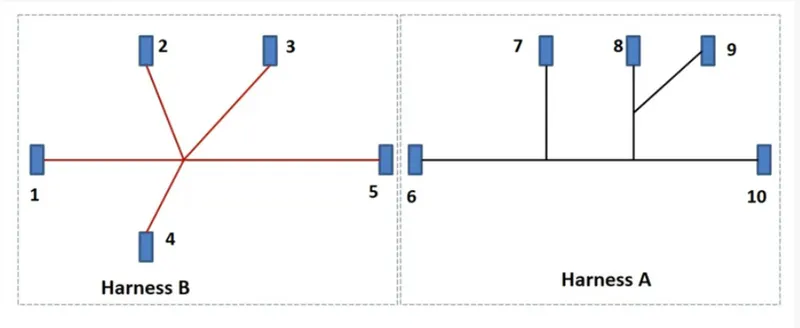
Route the following harness layout in Electrical workbench
OBJECTIVE:- Route the following harness layout in Electrical workbench. Make assumption for harness bundle diameters. Use the connectors provided. After completion of routing.
- Check the bundle Continuity. Add snap of result in submission
- Add annotation to all connectors. Make an assumptions for annotations like connect 1 , 2 etc
- Check for the bundle warning. Add snap.
- Generate CAT.part of harness assembly and convert is in. igs format.
DESIGN & ROUTING METHODOLOGY
- Download the Connectors 3D data from te.com or Given Link.
- Open the downloaded Connectors in Part Design workbench of Catia and Save as .CATPart
- Open each Connector and Create
- Connector Connection Point
- Bundle Entry Point
- Axis system on Connector Connection Point and Align the Y-Axis in Mating direction & X-Axis in the direction of Lock.
- Open each connector in Electrical Part Design workbench & Define Electrical properties.
- Click on Define Connector Symbol and then select the part.
- Click on Define Bundle Connection Point Symbol and fill the opened dialogue box.
- Click on Define Connector Connection Point Symbol and fill the opened dialogue box.
- Save the Part as Electrical Part.
- Create Product file in Assembly design workbench as Geometric_Bundle(Wiring_Harness_A)
- Add all connectors under the Geometric_Bundle(Wiring_Harness_A) in Assembly design workbench.
- Place all the connectors at desired locations as per given picture using Manipulation, Snap & Smart Move option.
- Now open the Geometric_Bundle(Wiring_Harness_A) in Electrical Harness Assembly workbench.
- Click on Geometrical Bundle Symbol and select Geometric_Bundle(Wiring_Harness_A) to defile Geometric_Bundle(Wiring_Harness_A) as Electrical.
- Now Click on Multi-branchable Symbol and fill the opened dialogue box.
- Bundle Diameter
- Bundle Bend Radius ( Ratio must be > 1.4 )
- Build Mode As slack
- Now Click on Route definition
- Select CT-DT04-08PA-C017 Connector and then C-YDTS26F15-35SNV001 connector and click Ok.
- Now click on Add branch Point Symbol and select the created bundle.
- Click on length and enter 100 and click ok.
- Now repeat last two steps to complete the given harness routing.
- Now repeat all Steps from the starting to create Harness B As per given fig. by name Geometric_Bundle(Wiring_Harness_B).
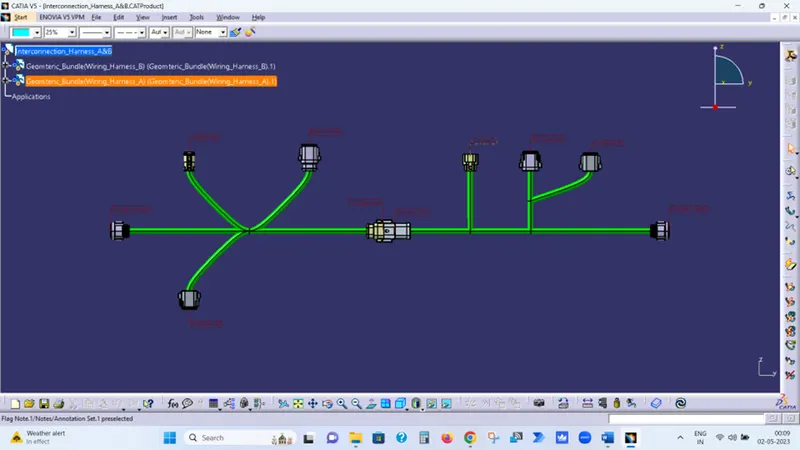
- Now Create one product file by name Interconnection_Harness_A&B and add Geometric_Bundle(Wiring_Harness_A) & Geometric_Bundle(Wiring_Harness_B) as Existing parts.
- Now adjust the position of Harness A & B to create interconnection between them.
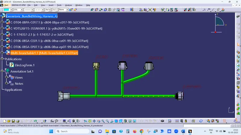
Harness A
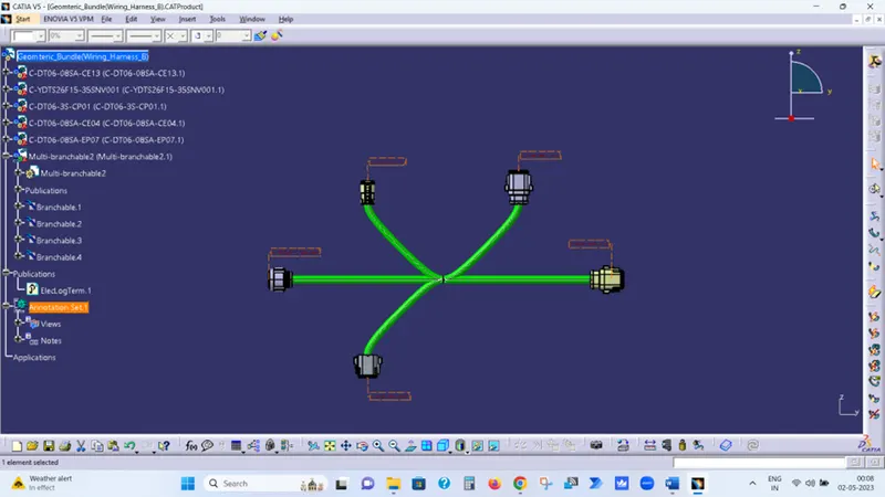
Harness B
Interconnection Harness A&B