Wiring harness design in CATIA V5 - 3D modeling Week 7 Challenge
Route the following harness layout in Electrical workbench
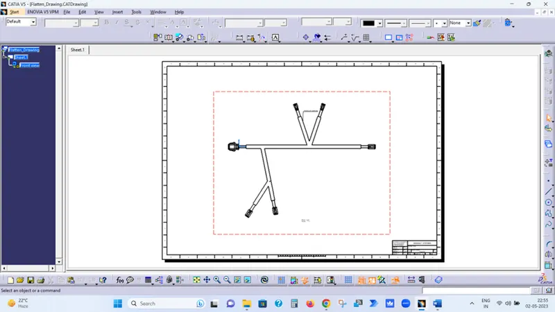
OBJECTIVE:- Flatten the harness assembly completed in “ week 4 challenge”. Place the flattened view on drawing sheet. Ensure bundles with protective coverings has different visuals on drawing view.
Download connector 3D data from www.te.com
- DT06-4S
- DT06-6S
- DT06-2S
- DT06-08SA
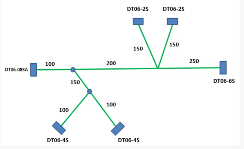
DESIGN & ROUTING METHODOLOGY
- Download the Connectors 3D data from te.com
- Open the downloaded Connectors in Part Design workbench of Catia and Save as .CATPart
- Open each Connector and Create
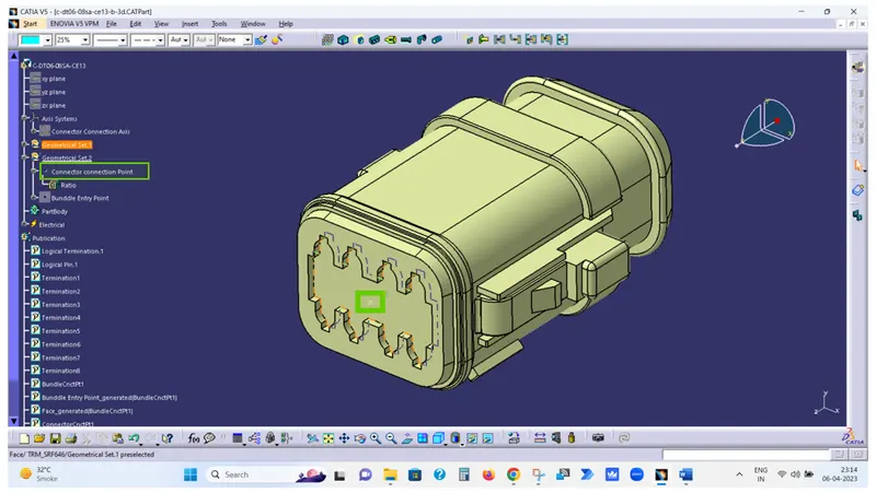
- Connector Connection Point
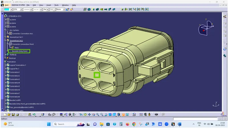
- Bundle Entry Point
- Axis system on Connector Connection Point and Align the Y-Axis in Mating direction & X-Axis in the direction of Lock.
- Open each connector in Electrical Part Design workbench & Define Electrical properties.
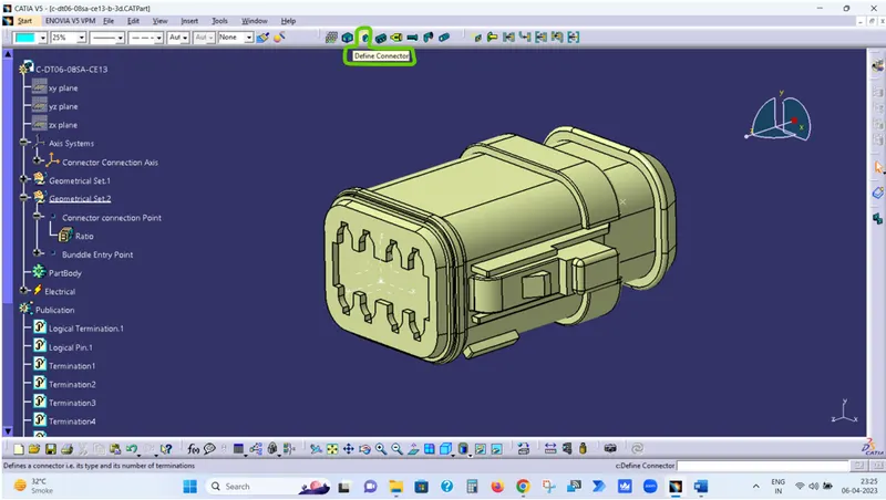
- Click on Define Connector Symbol and then select the part.
- Click on Define Bundle Connection Point Symbol and fill the opened dialogue box.
- Click on Define Connector Connection Point Symbol and fill the opened dialogue box.
- Save the Part as Electrical Part.
- Create one Product file in Assembly design workbench as Wiring Harness Context Assembly
- Create another Product file in Assembly design workbench as Geometric Bundle under Wiring Harness Context Assembly
- Add all connectors under the Geometric Bundle in Assembly design workbench.
- Place all the connectors at desired locations as per given picture using Manipulation, Snap & Smart Move option.
- Now open the Geometric Bundle Assembly in Electrical Harness Assembly workbench.
- Click on Geometrical Bundle Symbol and select Geometric Bundle Assembly to defile Geometric Bundle Assembly as Electrical.
- Now Click on Multi-branchable Symbol and fill the opened dialogue box.
- Bundle Diameter
- Bundle Bend Radius ( Ratio must be > 1.4 )
- Build Mode As slack
- Now Click on Route definition
- Select DT06-08SA Connector and then DT06-6S connector and click Ok.
- Now click on Add branch Point Symbol and select the created bundle.
- Click on length and enter 100 and click ok.
- Now repeat last two steps to complete the given harness routing.
- Now create Electrical harness Flattening file & define Harness Flattening Parameters
- Now click on Extract and select the File to be flatten i.e. Geometric Bundle
- Now click on Flatten to Flat the assembly.
- Now Create Drafting file to create the drawing of flatten Assembly.
- Select the Sheet Size As A0 & Place the view by clicking on Front View option.
- Now save the drawing file.
Harness Assembly Steps
Step-1 Download the Connectors 3D data from www.te.com
Step-2 Open the downloaded Connectors in Part Design workbench of Catia and Save as .CATPart
Step-3 Create one point on mating surface of Connector & rename it to Connector Connection Point.
Step-4 Create one point on Bundle Entry surface of Connector & rename it to Bundle Entry Point.
Step-5 Create Axis system on Connector Connection Point and Align the Y-Axis in Mating direction & X-Axis in the direction of Lock.
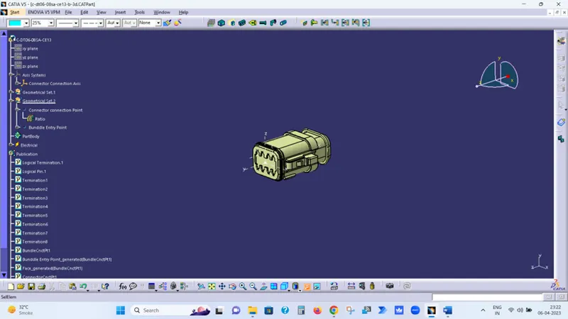
Step-6 Now open the Electrical Part Design workbench of Catia & Click on Define Connector Symbol and then select the part.
Step-7 Now click on Define Bundle Connection Point Symbol and fill the opened dialogue box.
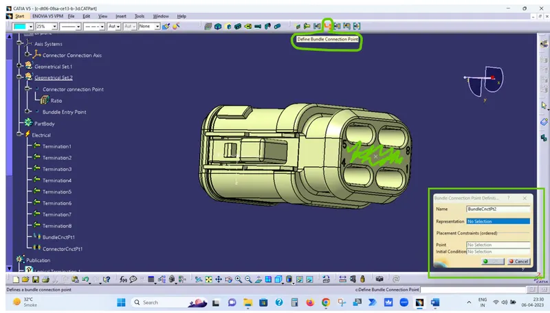
In Representation – Select the Green Highlighted Surface
In Point – Select the Bundle Entry Point
In Initial Conditions – Select the Green Highlighted Surface
Step-8 Now click on Define Connector Connection Point Symbol and fill the opened dialogue box.
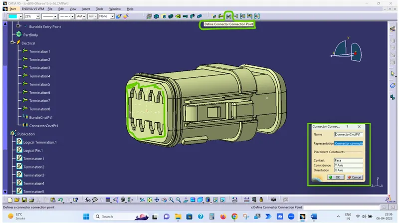
In Representation – Select the Connector Connection Point
In Contact – Select the Green Highlighted Surface
In Coincidence – Select the Y-Axis
In Orientation – Select the X-Axis
Step-8 Save the Part as Electrical Part.
Step-9 Repeat same Steps for all Connectors & save the as Electrical Part.
Step-10 Create one Product file in Assembly design workbench as Wiring Harness Context Assembly
Step-11 Create another Product file in Assembly design workbench as Geometric Bundle under Wiring Harness Context Assembly
Step-12 Add all connectors under the Geometric Bundle in Assembly design workbench.
Step-13 Place all the connectors at desired locations as per given picture using Manipulation, Snap & Smart Move option.
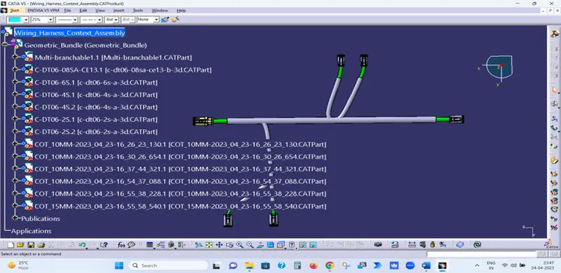
Step-14 Now open the Geometric Bundle Assembly in Electrical Harness Assembly workbench.
Step-15 Click on Geometrical Bundle Symbol and select Geometric Bundle Assembly to defile Geometric Bundle Assembly as Electrical.
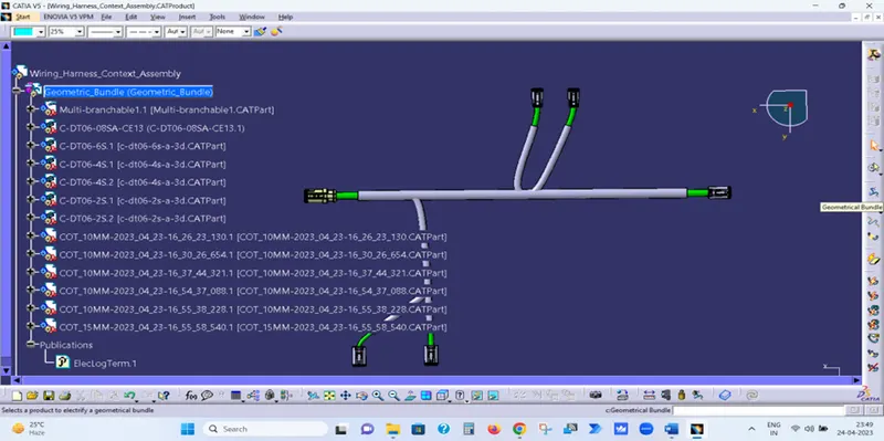
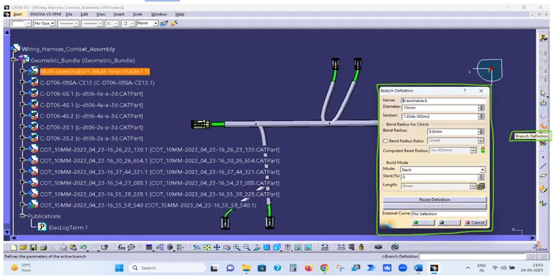
Step-16 Now Click on Multi-branchable Symbol and fill the opened dialogue box.
- Bundle Diameter
- Bundle Bend Radius ( Ratio must be > 1.4 )
- Build Mode As slack
Step-17 Now Click on Route definition
- Select DT06-08SA Connector and then DT06-6S connector and click Ok.
- Now click on Add branch Point Symbol and select the created bundle.
- Click on length and enter 100 and click ok.
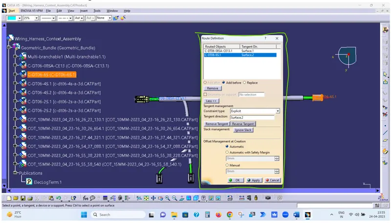
Step-18 Now repeat last two steps to complete the given harness routing.
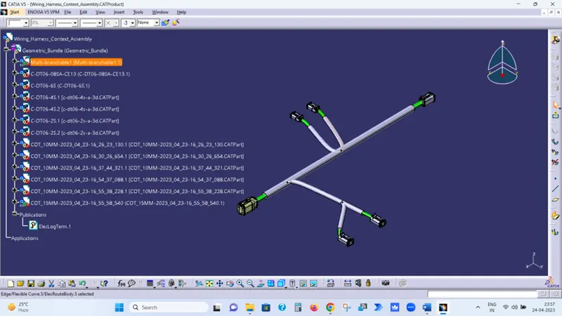
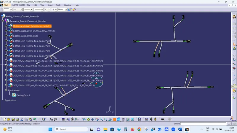
Step-19 Now create Electrical harness Flattening file & define Harness Flattening Parameters
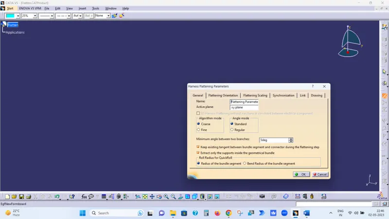
Step-20 Now click on Extract and select the File to be flatten i.e. Geometric Bundle
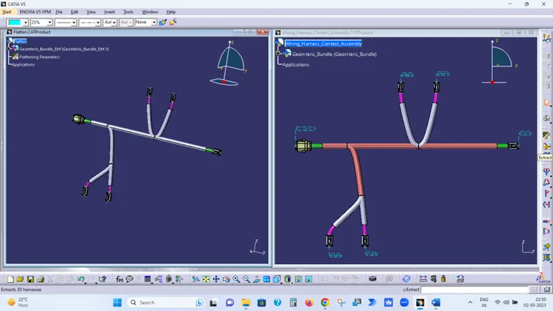
Step-21 Now click on Flatten to Flat the assembly.
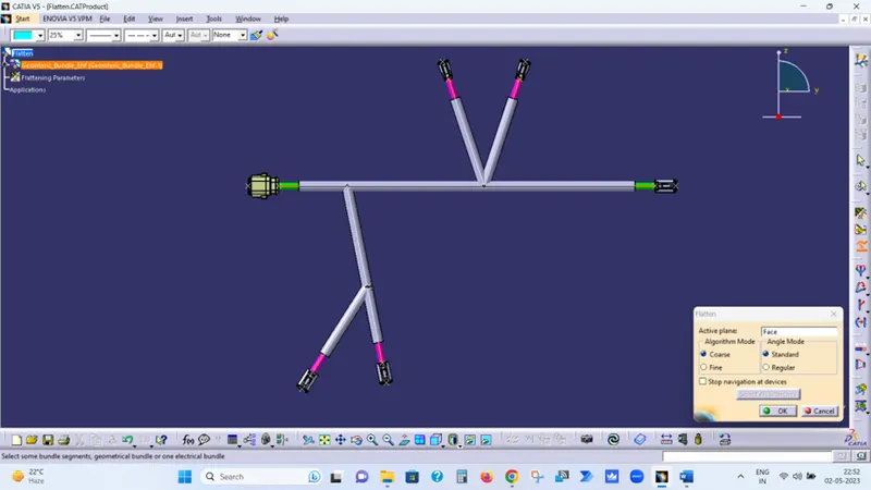
Select the desire plan i.e., Face of Connector
Then select the Geometric_Bundle_Ehf and click ok to flatten the assembly.
Step-22 Now Create Drafting file to create the drawing of flatten Assembly.
Step-23 Select the Sheet Size As A0 & Place the view by clicking on Front View option.
Step-24 Now save the drawing file.