Project 2
Route the following harness layout in Electrical workbench
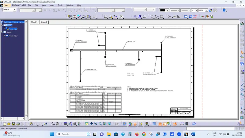
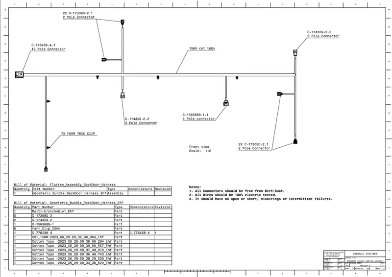
OBJECTIVE:- Route the Wiring harness on Given car body and Prepare flatten view drawing in CATIA V5.
Download connector 3D data from www.te.com
INTRODUCTION
A wire harness, also commonly referred to as a wiring harness, is an exterior sheath used to cover some types of electronic wires. Generally, wiring harnesses are made of thermoplastic or thermoset materials that can help protect the cables from the environment.
Automobiles today come with some great features. Their design, though, calls for deft wiring considerations. An automotive wiring harness is an assembly of wires, connectors, and other electrical parts. You use it in a vehicle for the transmission of signals.
Design of Wire Harness
The design of the harness comprising of the interconnected mesh of wires is crucial. Select the important components like connectors, fuses, and sensors. Ensure their reliability.
Study the schematic circuit diagram. Divide the entire vehicle into detachable parts like chassis, body, and engine. Then design the wiring harness that suits the requirements. Ensure that it fits the customer requirements, shape, and size of the vehicle. Chalk out electrical routing in a way that reduces complexity and uses minimal space.
There are three types of engine wire harnesses based on the vehicle part you are looking at. The engine wire harness is a set of wires, connectors, and terminals to relay the signal to and from the engine. It also communicates messages from all sensors within the engine.
The body wiring harness routes electrical and electronic bits of information. It’s what keeps the major components of the automobile working. The body wiring takes care of power windows, lighting, and other accessories. And then, you need a chassis wiring harness for connecting the components.
Door Wiring Harness
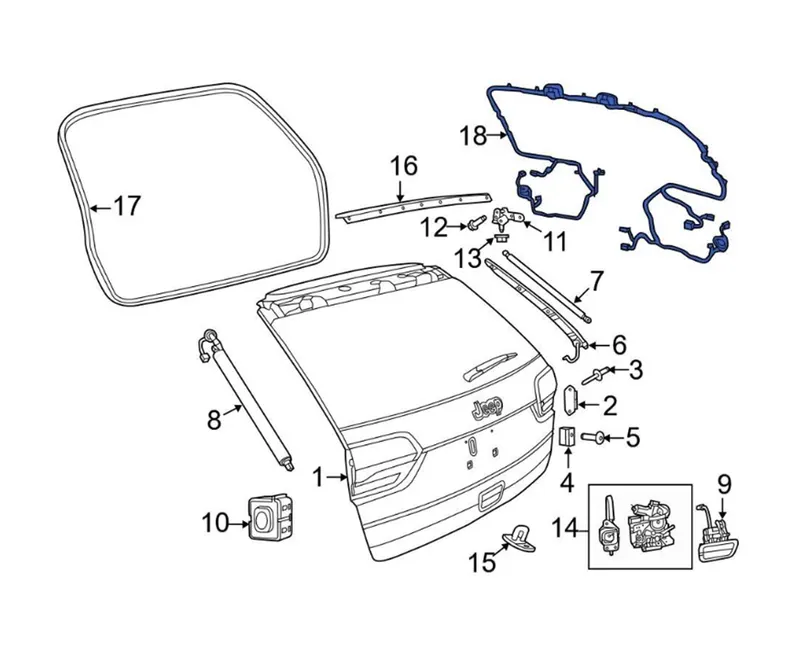
In the case of car doors, as the door of the automobiles opens and closes, the wires bend. If you use the car every day, the door will open and close many times. In case of Back door, the trunk could be open and close many times in daily life. Backdoor wiring harness mainly introduced to connect the brake lights, number plate lights, rear wiper motor, defogger connections. The harness routing should be maintained properly with all the supporting components like clips, clamps with proper protective covers, rubber grommets.
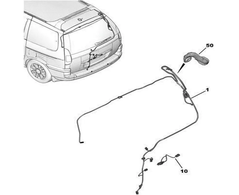
DESIGN & ROUTING METHODOLOGY
- Download the Connectors 3D data from te.com
- Open the downloaded Connectors in Part Design workbench of Catia and Save as .CATPart
- Open each Connector and Create
- Connector Connection Point
- Bundle Entry Point
- Axis system on Connector Connection Point and Align the Y-Axis in Mating direction & X-Axis in the direction of Lock.
- Open each connector in Electrical Part Design workbench & Define Electrical properties.
- Click on Define Connector Symbol and then select the part.
- Click on Define Bundle Connection Point Symbol and fill the opened dialogue box.
- Click on Define Connector Connection Point Symbol and fill the opened dialogue box.
- Save the Part as Electrical Part.
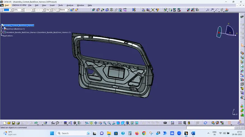
- Create one Product file in Assembly design workbench as
- Create another Product file in Assembly design workbench as Geomteric_Bundle_BackDoor_Harness under Assembly_Context_BackDoor_Harness
- Add all connectors under the Geomteric_Bundle_BackDoor_Harness in Assembly design workbench.
- Place all the connectors at desired locations as per given picture using Manipulation, Snap & Smart Move option.
- Now open the Geomteric_Bundle_BackDoor_Harness in Electrical Harness Assembly workbench.
- Click on Geometrical Bundle Symbol and select Geomteric_Bundle_BackDoor_Harness to defile Geomteric_Bundle_BackDoor_Harness as Electrical.
- Now Click on Multi-branch able Symbol and fill the opened dialogue box.
- Bundle Diameter
- Bundle Bend Radius ( Ratio must be > 1.4 )
- Build Mode As slack
- Now Click on Route definition
- Select C-776438-4.1 Connector & Furr Tree Clip.
- Now repeat last steps to complete the given harness routing.
- Now create Electrical harness Flattening file & define Harness Flattening Parameters
- Now click on Extract and select the File to be flatten i.e. Geomteric_Bundle_BackDoor_Harness
- Now click on Flatten to Flat the assembly.
- Now Create Drafting file to create the drawing of flatten Assembly.
- Select the Sheet Size As A0 & Place the view by clicking on Front View option.
- Now save the drawing file.
Harness Assembly Steps
Step-1 Download the Connectors 3D data from www.te.com
Step-2 Open the downloaded Connectors in Part Design workbench of Catia and Save as .CATPart
Step-3 Create one point on mating surface of Connector & rename it to Connector Connection Point.
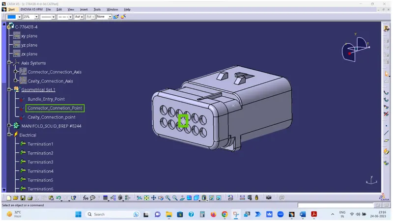
Step-4 Create one point on Bundle Entry surface of Connector & rename it to Bundle Entry Point.
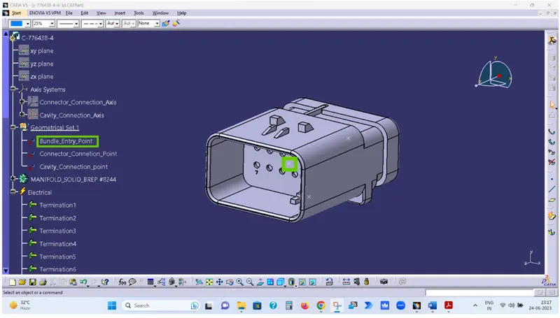
Step-5 Create Axis system on Connector Connection Point and Align the Y-Axis in Mating direction & X-Axis in the direction of Lock.
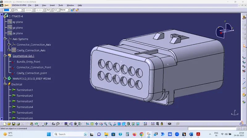
Step-6 Now open the Electrical Part Design workbench of Catia & Click on Define Connector Symbol and then select the part.
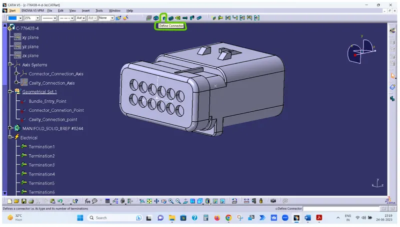
Step-7 Now click on Define Bundle Connection Point Symbol and fill the opened dialogue box.
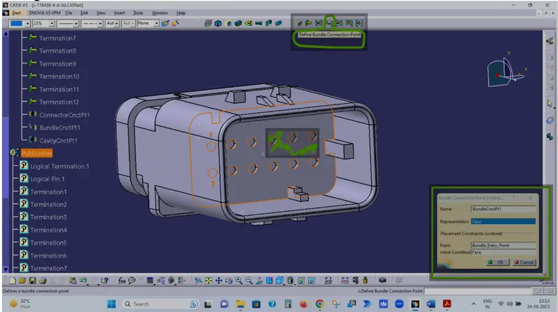
In Representation – Select the Green Highlighted Surface
In Point – Select the Bundle Entry Point
In Initial Conditions – Select the Green Highlighted Surface
Step-8 Now click on Define Connector Connection Point Symbol and fill the opened dialogue box.
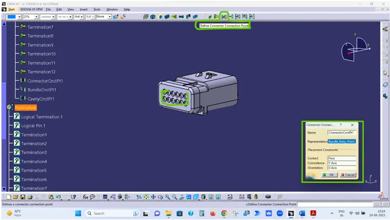
In Representation – Select the Connector Connection Point
In Contact – Select the Green Highlighted Surface
In Coincidence – Select the Y-Axis
In Orientation – Select the X-Axis
Step-9 Save the Part as Electrical Part.
Step-10 Repeat same Steps for all Connectors & save the as Electrical Part.
Step-11 Create one Product file in Assembly design workbench as Assembly_Context_BackDoor_Harness
Step-12 Create another Product file in Assembly design workbench as Geomteric_Bundle_BackDoor_Harness under Assembly_Context_BackDoor_Harness
Step-13 Add all connectors under the Geomteric_Bundle_BackDoor_Harness in Assembly design workbench.
Step-14 Place all the connectors at desired locations as per given picture using Manipulation, Snap & Smart Move option.
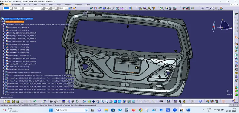
Step-15 Now open the Geomteric_Bundle_BackDoor_Harness in Electrical Harness Assembly workbench.
Step-16 Click on Geometrical Bundle Symbol and select Geomteric_Bundle_BackDoor_Harness to defile Geomteric_Bundle_BackDoor_Harness as Electrical.
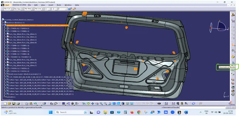
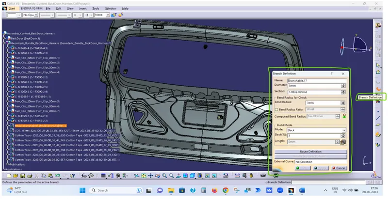
Step-17 Now Click on Multi-branch able Symbol and fill the opened dialogue box.
- Bundle Diameter
- Bundle Bend Radius ( Ratio must be > 1.4 )
- Build Mode As slack
Step-18 Now Click on Route definition
- Select C-776438-4.1 Connector & Furr Tree Clip.
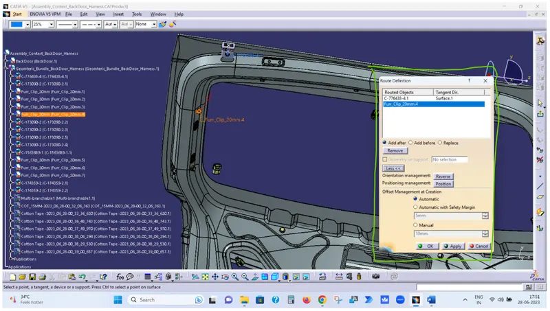
Step-19 Now repeat last two steps to complete the given harness routing.
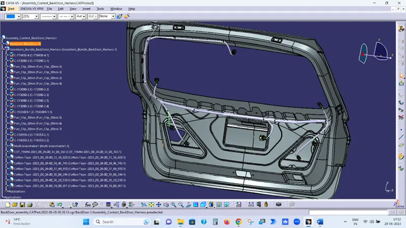
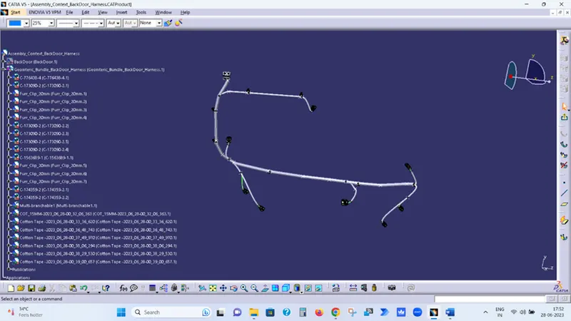
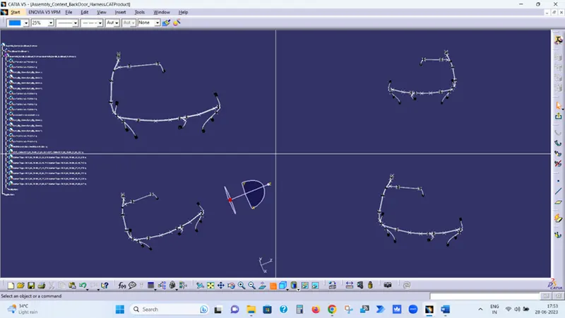
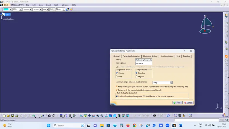
Step-20 Now create Electrical harness Flattening file & define Harness Flattening Parameters
Step-21 Now click on Extract and select the File to be flatten i.e. Geometric Bundle
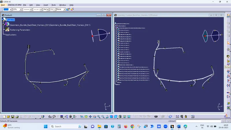
Step-22 Now click on Flatten to Flat the assembly.
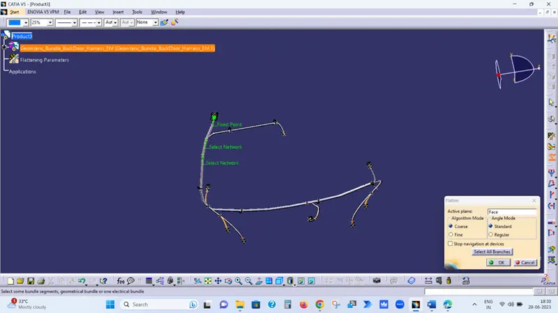
Select the desire plan i.e., Face of Connector
Then select the Geometric_Bundle_Ehf and click ok to flatten the assembly
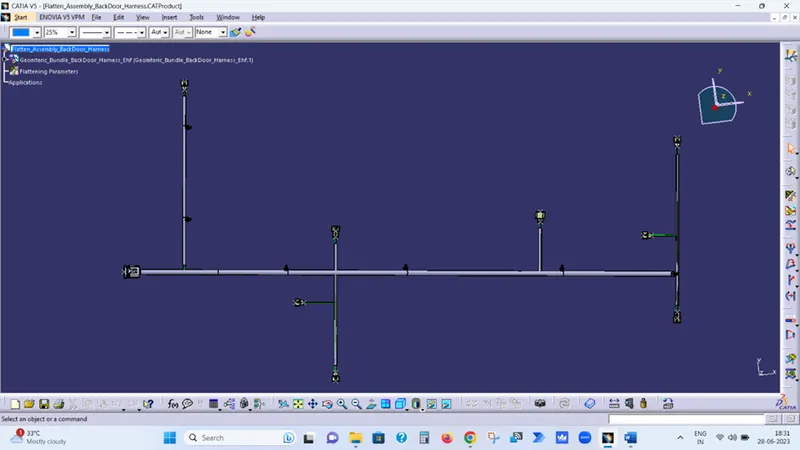
Step-23 Now Create Drafting file to create the drawing of flatten Assembly.
Step-24 Select the Sheet Size As A0 & Place the view by clicking on Front View option.
Step-25 Now save the drawing file.