Roof Design
HOOD DESIGN
OBJECTIVE:- For the Given Roof styling, create an ASSEMBLY by developing the essential flanges for the outer roof and creating the reinforcements.
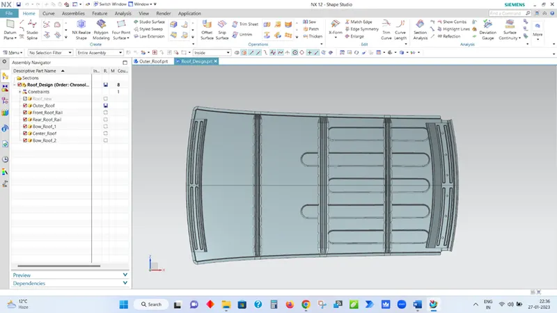
Complete Roof Assembly
INPUTS
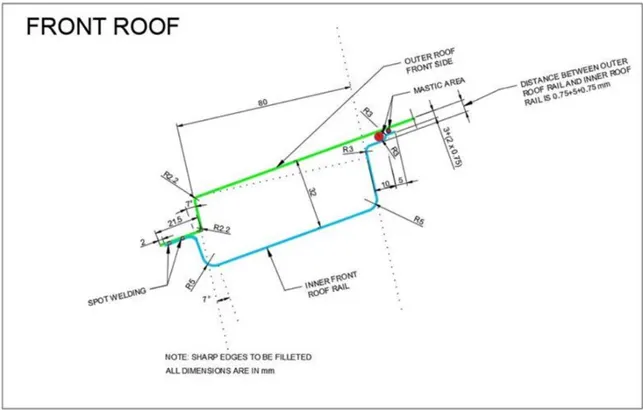
- Outer Panel Thickness = 0.75mm
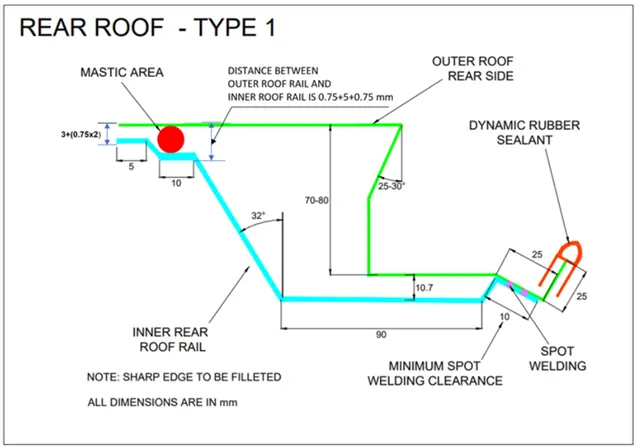
Rear Roof Rail Master Section
Rear Roof Rail Master Section
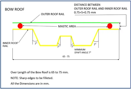
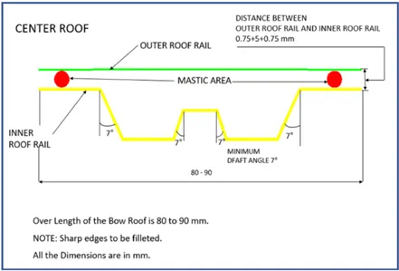
Bow Roof & Center Roof Master Section
Design Consideration Of Roof:
- Visibility criteria
- Head Room Clearance
- Reinforcement Of Roof ( Bow Roof & Centre Roof )
- Manufacturing Feasibility
Design Procedure
- Design of Front Roof Rail as per Master Section & Providing Emboss and Slots for Improving strength to facilitate for cabin lamp mounting.
- Design of Bow Roof following master section & providing mastic points for proper joining of Outer roof & Bow roof.
- Design of Centre Roof following master Section.
- Draft Analysis of All Designed Parts.
- Assembly of Outer Roof, Bow roof 1 & 2, Front Roof Rail, Rear Roof Rail.
- Calculating Heat Distortion & Snow Load Condition to Justify Bow Roof & Centre Roof Position.
Roof Design
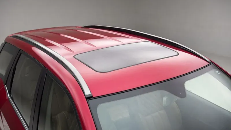
An automobile roof or car top is the portion of an automobile that sits above the passenger compartment, protecting the vehicle occupants from sun, wind, rain, and other external elements.
Visibility criteria
While designing roof and its components one major factor is Visibility Criterial, every Vehicle have predefine visibility Criteria.
Front Roof Rail & Rear Roof Rail should be Designed keeping in mind that visibility of occupant should not hinder or reduced due to design of roof rails.
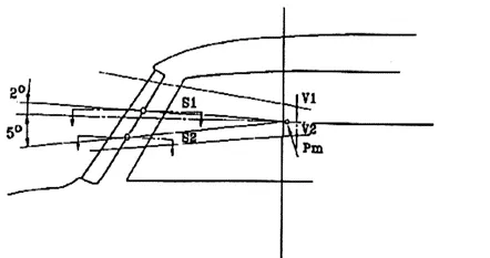
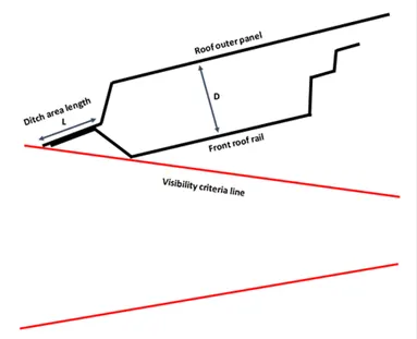
As shown in the above picture as length L ‘which is the length of the front ditch area ‘ increases , its going to reduce the visibility. Also as the depth of the Front roof rail D increases after a certain value it will start hindering the visibility of occupant.
Head Room Clearance
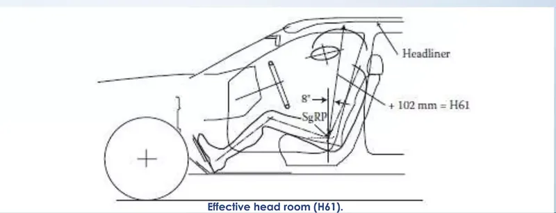
Head Room Clearance is space between the occupants head and Roof liner, As the width of the Front Roof rail increases ,the Head room clearance is getting reduced.so its necessary to maintain the width of the Front Roof Rail according to the Head room clearance data.
Reinforcement Of Roof ( Bow Roof & Centre Roof )
- Reinforcements such as Bow Roof & Centre roof is provided to improve the strength of roof.
- The longer the roof the more reinforcement it needed.
- Vehicles having small roof can have only one Reinforcement roof or no reinforement roof.
- Vehicle with longer and Flat roof require reinforcement.
- Reinforcement roofs are positioned at most flat area to increase the strength of roof.
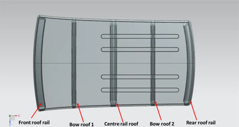
For Positioning of Reinforcement roof Curvature Study should be done.
Heat distortion study:
This study is done to check how the sheet metal components perform in the extreme heat conditions. Sheet metals have tendency to change its shape in high temperatures. To avoid any failure of sheet metal components this study is done to determine its capacity.
Bow – roof prediction Formula
W = [1.73 x 10^ (-3) x L] + [1.85 x 10^(-8) x (R^2)/t] + [ 1.10x10^(-3) x l] - 2.68
Judgement Condition: OK< 2.7
Where,
L = Roof Length in X-Direction[mm](Roof dimension in 0-Y)
R = Roof curvature
R = 2(Rx*Ry)/(Rx+Ry)
Rx = X curvature
Ry = Y curvature
t = Roof plate thickness [mm]
l = Bow Roof Span [mm]
Snow Load Prediction Formula
Qr = [Iy x t2] / [α x s x [(Rx + Ry)/2]2 x 10-8]
Where,
α = My x Lx^2 x 10^-12, My = Y(Ly-Y)
Judgement condition = Qr ≥ 3.1
250 ≤ s ≤ 380
t = Roof plate thickness [mm]
Ly = Distance between the front and rear roof Rails on the Vehicle along with 0Y[mm] Length of Roof panel with the center point between Roof rail Front /Rear as the reference point of the front and the rear.
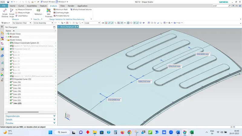
Lx = Distance between the Left and Right end of the roof on the Roof BOW [mm] Width of the roof panel exposed on the surface.
Y = Distance front Front Roof Rail to Roof BOW[mm]
s = Distance for which Roof BOW bears divided load [mm]
s = L1/2 + L2/2
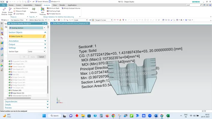
Iy = Geometrical moment of inertia of Roof BOW (Y cross-section) [mm4]
Rx = Lateral direction curvature radius of roof panel Y cross-section on Roof BOW [mm]Roof panel curvature Radius of the Length Lx in Front view
Ry = Longitudinal Direction curvature radius of the Roof panel X cross-section on Roof BOW [mm] Roof panel X curvature radius of length s in Side view
Manufacturing Feasibility /Drawability (Draft Analysis)
Deep drawing
Deep drawing is a sheet metal forming process in which a sheet metal blank is radially drawn into a forming die by the mechanical action of a punch. It is thus a shape transformation process with material retention. The process is considered "deep" drawing when the depth of the drawn part exceeds its diameter. This is achieved by redrawing the part through a series of dies. The flange region (sheet metal in the die shoulder area) experiences a radial drawing stress and a tangential compressive stress due to the material retention property. These compressive stresses (hoop stresses) result in flange wrinkles (wrinkles of the first order). Wrinkles can be prevented by using a blank holder, the function of which is to facilitate controlled material flow into the die radius. The feasibility of this deep drawing is called Drawability.
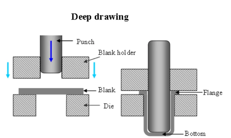
Every part must have a draft of atleast 7 degree for Easy ejection from tool & Die and Better life of Tool.
Designing Roof Assembly From Given Data
Front Roof Rail Design
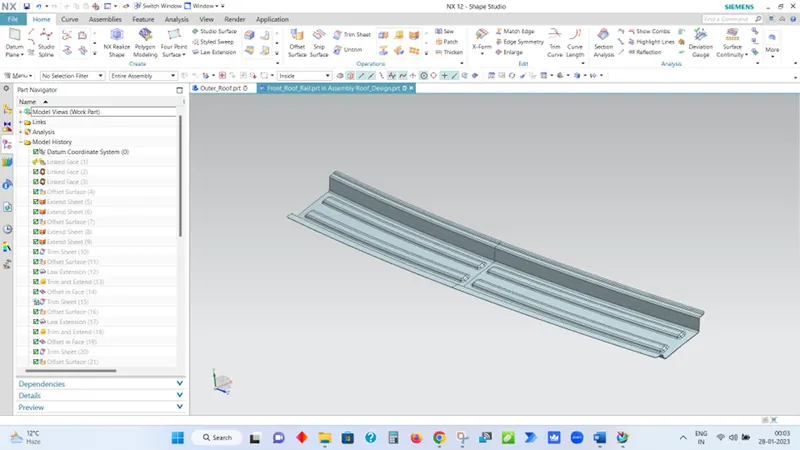
Front Roof Rail is designed Considering the Master Section and Emboss is provided to Improve the strength.
Draft Analysis Of Front Roof Rail
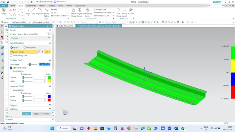
As Shown in fig. Front roof rail is having 7 degree draft. For easy manufacturing of part.
Bow Roof 1,2 & Centre Roof Design
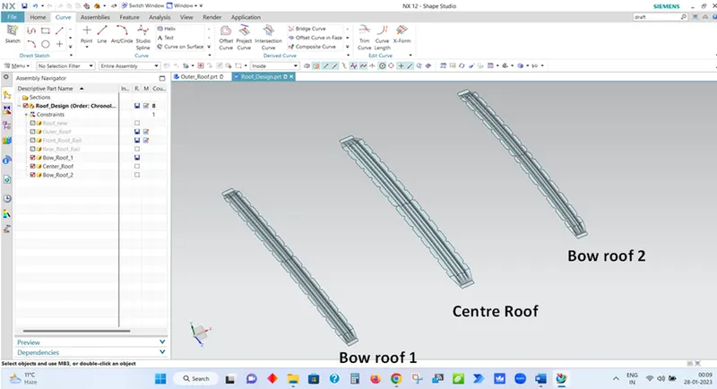
Reinforcement roofs are designed Considering the Master Section and Mastic Points are provided for Joining Reinforcement Roof with Outer Roof.
Draft Analysis Of Bow Roof 1,2 & Centre Roof
Bow Roof 1
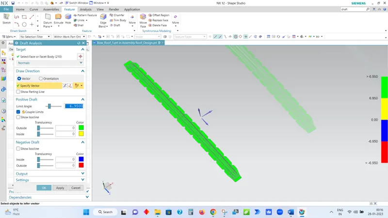
As Shown in fig. Bow roof 1 is having 7 degree draft. For easy manufacturing of part.
Bow Roof 2
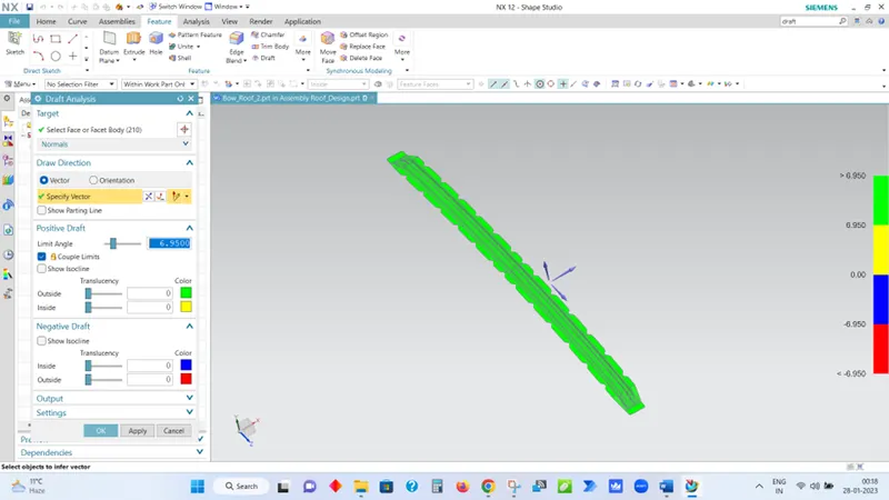
As Shown in fig. Bow roof 2 is having 7 degree draft. For easy manufacturing of part.
Centre Roof
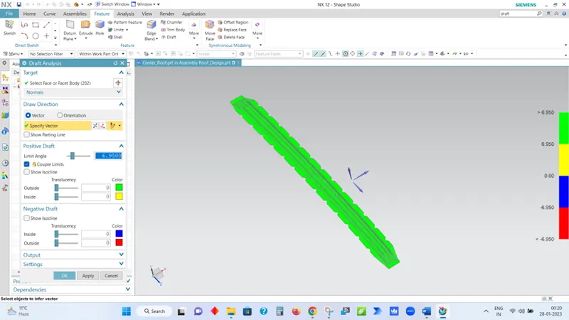
As Shown in fig. Centre roof is having 7 degree draft. For easy manufacturing of part.
Rear Roof Rail Design
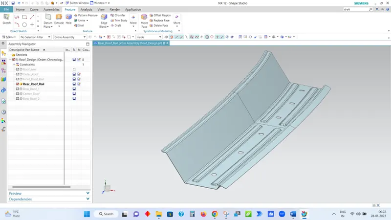
Rear Roof Rail is designed Considering the Master Section and Emboss is provided to Improve the strength.
Draft Analysis Of Rear Roof Rail
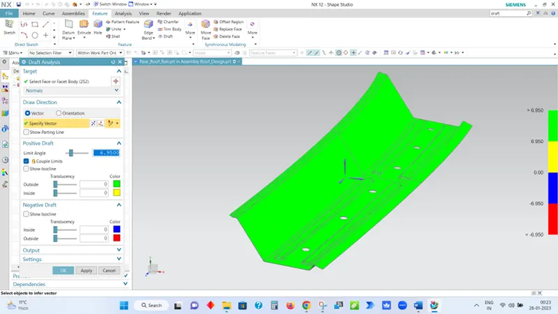
As Shown in fig. rear roof rail is having 7 degree draft. For easy manufacturing of part.
Heat Distortion & Snow Load Calculation To Justify the Position Of Reinforcement Roofs i.e Bow Roof 1, Centre Roof & Bow Roof 2
Heat distortion study:
This study is done to check how the sheet metal components perform in the extreme heat conditions. Sheet metals have tendency to change its shape in high temperatures. To avoid any failure of sheet metal components this study is done to determine its capacity.
Bow – roof prediction Formula
W = [1.73 x 10^ (-3) x L] + [1.85 x 10^(-8) x (R^2)/t] + [ 1.10x10^(-3) x l] - 2.68
Judgement Condition: OK< 2.7
Where,
L = Roof Length in X-Direction[mm](Roof dimension in 0-Y) = 2028.7
R = Roof curvature
R = 2(Rx*Ry)/(Rx+Ry)
Rx = X curvature
Ry = Y curvature
t = Roof plate thickness [mm] = 0.75
l = Bow Roof Span [mm]
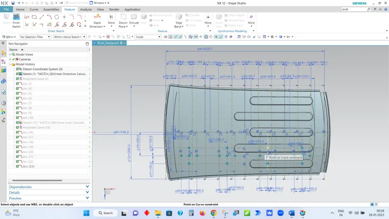
RX & RY (X & Y Curvature):
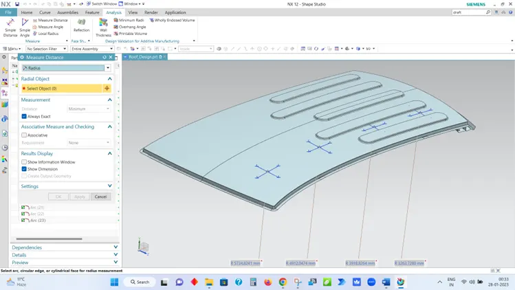
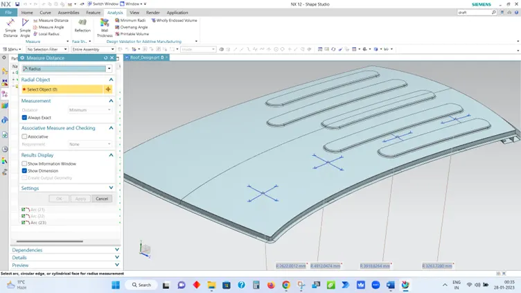
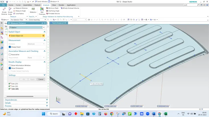
From 0-Y axis, at -3Y about distance 300mm is drawn parallel on the perpendicular plane. After that 100mm lines are offset to either side of -3Y line. Now center lines are drawn between each adjacent roof rail edges respectively. Intersection points are marked on the sketch. Make all geometry lines are construction lines except points.
Project the intersection points on sketch to the Roof surface.
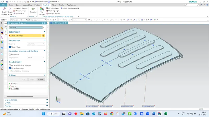
Join the intersection points in roof surface using the arc curve an measure the radius using the minimum radius comment.
Rx Value
Ry Value
FINAL RESULTS OF HEAT DISTORTION:
We have the necessary values for finding the heat distortion value(W):
W = [1.73 x 10^(-3) x L] + [1.85 x 10^(-8) x (R^2)/2] + [1.10 x 10^(-3) x I]-2.68
Apply the all the values,
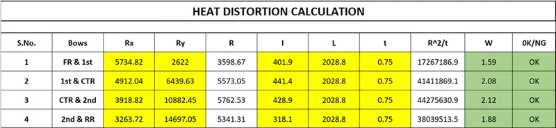
From above result we can conclude that all the values are of W< 2.7 which means that all bow roofs are placed at the right place.
SNOW LOAD:
Snow load criteria study is used to check the durability of the roof to withstand the snow fall on the roof and reflex it is original shape without any permanent deformation after load being removed.
SNOW LOAD CRITERIA:
Qr = [IY x t2] / [α x s x [(RX + RY)/2]2 x 10-8]
Where,
α = My x LX2 x10-12, My = Y(Ly–Y)
Judgement condition = Qr > 3.1
250 < s < 380
t = Roof plate thickness[mm] = 0.75 mm
LY = Distance between the front and rear roof rails on the vehicle along with 0Y[MM],Length of roof panel with the center point between roof rails front/ rear as the front and rear reference point.
LX= Distance between the left and right end of the roof on the roof bow[mm],With of the roof panel exposed on the surface.
Y = Distance between Front roof rails to roof bow [mm],
s = Distance for which roof bow bears divided load [mm],
s = L1/2 + L2/2
Iy = Geometrical moment of inertia of roof bow (Y cross – section) [mm4],
RX = Lateral direction curvature radius of roof panel Y cross section on roof bow [mm4], Roof panel curvature radius of the length LX in front view.
RY = Longitudinal direction curvature radius of the roof panel X cross section on roof bow[mm4], Roof panel X curvature radius of length s in side view.
RX & RY (X & Y Curvature):
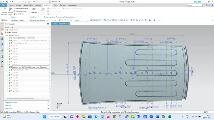
At 0-Y axis on perpendicular plane to roof. Draw 100mm lines offset to either side of the of 0Y axis line. Now center lines are drawn between each adjacent roof rail respective. Intersection points are marked on the sketch. Make all the geometry in construction lines except points.
Project the intersection points in the sketch are projected to roof surface.
Join the project points using arc curve and measure the radius value using minimum radius comment.
Rx Value
Ry Value
Lx value
MOI Of Bow Roof 1
MOI Of Centre Roof
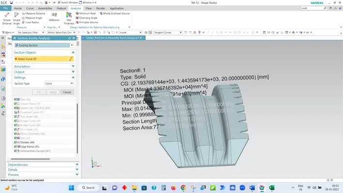
MOI Of Bow Roof 2
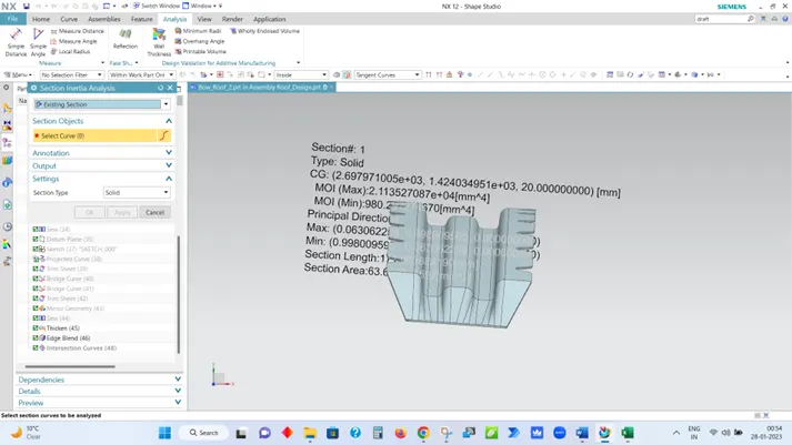
FINAL RESULTS OF SNOW LOAD CRITERIA:
We have the necessary values for finding the Snow load value(Qr):

As the above table shows all values are above 3.1 that means snow load condition is satisfied I.e Qr > 3.1
After above Calculation Heat distortion & snow load condition we can conclude that the position of Reinforcement is Ok.
Even though Both condition are satisfied I have created Emboss on Outer roof For asthetical purpose and providing additional strength in back Flat area of outer roof.