Week 9 - Project - Master Section Development
B PILLAR DESIGN THROUGH MASTER SECTION DEVELOPMENT
AIM:
The objective of this project to develop Closed Surface Model using Master Sections and to develop attachment features for Fixation of Parts by following OEM Design standards and procedures in CATIA SURFACE WORKBENCH and PART DESIGN.
ABSTRACT:
Pillars are the vertical or near-vertical supports of a car's window area or greenhouse, designated respectively as the A, B, C, or (in larger cars) D-pillar, moving from front to rear B Pillar is the central pillar of the car. It is the most complex component or structure of the vehicle body. This is because the front door attaches to the B pillar and the rear door hinges to the B pillar. The B Pillar is welded to the top panel of the car and the floor panel of the car. Hence B-Pillar provides structural support to the roof.
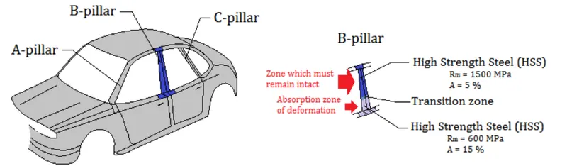
Fig :-Pillars In a Car
A surface:
A surface is the styling surface that is visible to the consumer and gives an aesthetic look for the model designed. Surfaces which is having curvature continuity is also called Class A Surface. Engineering features are not added to this surface.
B Surface:
Class B surfaces are the secondary surfaces that you can see sometimes includes all the engineering features such as dog house, locators, ribs, flanges, etc. This surface is the direct offset of the Class A surface which gives thickness to the component.
C Surface:
This surface is the combination of the Class A and Class B surfaces also they are the backside surfaces that can have tool marks, flash, and other imperfections without hurting appearance, function, etc...
Tooling Axis:
It is the direction in which the component is removed from the mold cavity.
Dog House:
Dog house is an engineering feature used in plastic trim design. Dog houses are used as supporting feature. Sometimes other engineering features like snaps; locators etc. are mounded on them to increase their strength. Dog houses are subjected to draft analysis to prevent breakage of the component during ejection from mould cavity. Dog house and other engineering components are built on B-surface.
Ribs:
Ribs are a feature in plastic injection moulded parts. They are thin extensions that run perpendicular from a wall or plane. They are commonly used to provide additional support and strength to a part.
Thickness and location are essential to rib design. Here are some helpful design guidelines:
- They should be designed with a thickness that is ½ the wall thickness to avoid a thick section at the wall base.
- To minimize sink marks, design ribs that are approximately 60% of the joining wall thickness for minimum risk.
- Best practices include spacing at a distance of at least twice the wall thickness.
- Glossy materials require a thinner rib (40% of wall thickness).
1. Creating a Class B surface from a given Class A :
- To create a Class B surface from Class A,
- First, we offset Class A for 2mm given the thickness value.
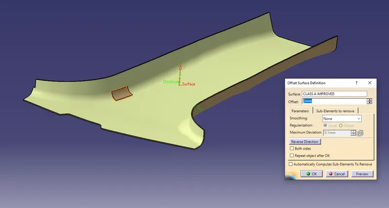
- After offsetting the surface we get patches and the surface is missing on the offset so we need to fix it first.
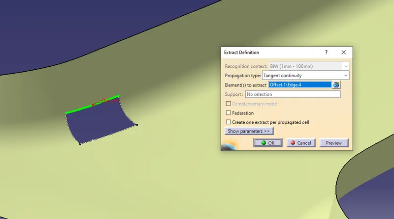
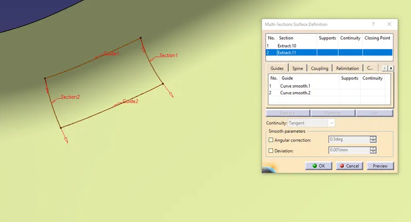
- For that, we are using the Multi-sections surface command by extracting the edges of the patches separately and smoothen the guide curves.
Use the Multi-sections surface to avoid any gap.
3. Creating the Flanges on the Class B surface :
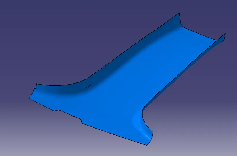
- In the given Class A input, we do not get any Flanges but when we look at the Master section, there are flanges present in the intersection.
- Master sections are the guides for design requirements that decide the component packaging after technical (Styling, Concept, or Class-A) surfaces.
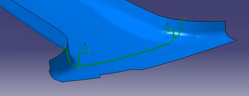
So, we make flanges on both sides so that we extract the boundaries of the B surface by tangent continuity and make it smooth by curve smooth command to curvature continuity to avoid issues while sweeping.
- Then, the plane is created along the master section and the B surface intersected with these planes.
- The purpose of intersecting the surface is to have the reference of the sweep surface match with the master section lines.
- Now, the boundary is swept with a reference surface until it is parallel or aligned with the B side of the master section. Later, this flange is trimmed to join with the B surface and the same can be done for the other side and the A surface also. In the end, edge fillets are provided by measuring from the master section.
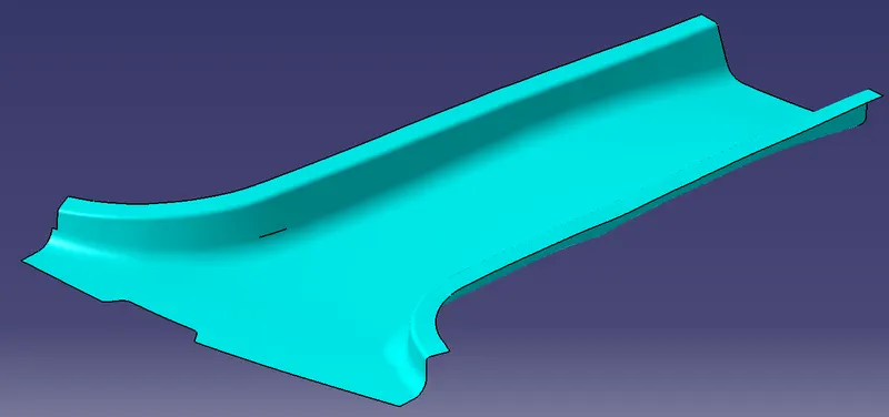
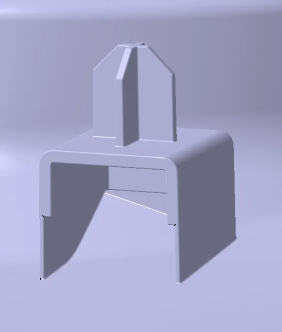
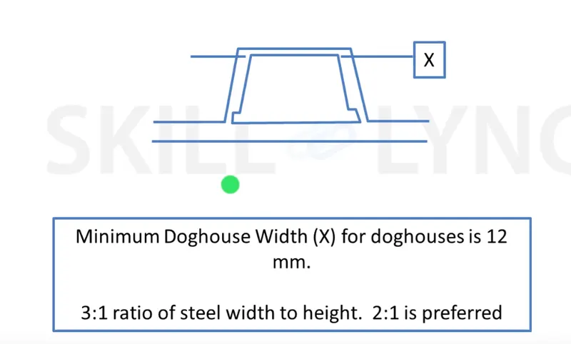
Doghouse
Using The Master Section The Doghouse Is Created And Then Part Modelled Using Thickness Option
.The 4 Way Locator Is Formed Above The Dog House Which Locates The B Pillar Towards The Mating Surfaces
.The Dog House Design Rules Are
.The Thickness Of The Connecting Surface Towards B Side Should Be 40% Off The Main Thickness
.The Walls Are Drafted With Min 0.5 Degrees Along The Main Tooling Direction
.The Attachement Feature Created Needs a Seperate Tooling Axis To Clear The Part Hence a Lifter Axis Is Used
.The Surfaces That Are Cleared Along The Lifter Axis Are Also Given a Minumal Draft
.The Height Of The Attahcment Walls Should Be a Minimum Of 3 Mm
.This Avoids The Plastic Defects On The B Side And Maintains The Texture Of A Side
.Four Way Locators Are Tapered Along The Edges To Create An Entry Point For Locators And The Locator Walls Are Drafted Along The Main Tooling Direction.
The Walls Are Minimum Of Above 0.4 Times Of The Total Thickness To Avoid Shot Incapacity During Plastic Product Creations And The Apex Walls Are Ensured To Enough For Creation Of Parts.
Ribs
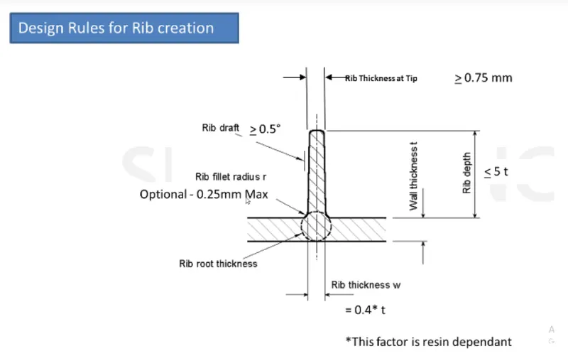
Ribs Provide Stifness To The Parts And Can Be To Impart Thougness Whthout Increasing The Part Thickenss And Are Locators And Provide Allignment To The Mating Parts
The Design Rules For Two Way And Four Way Fixtures Are
.Rib Wall Thickness Should Be 0.4 Times Of Thickness Of The Part
.The Drafted Walls Of Rib Should Be Within 0.5 Degrees
.The Top Height Of Rib Should Be At Least 0.70 Mm Thick To Allow The Molten Plastic To Reach The Top To Avoid Short Shot
.The Thickness Of The Rib, Fillet Radius, Draft And Rib Root Thickness Are Measured And Are Withing The Design Specifications
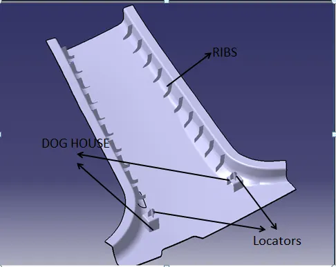
.In B Pillar The Ribs Are 50mm Apart On Both Sides
.Thus B Pillar Cover Is Surface Development Is Completed And Attachment Features Are Added.
.It Should Be Noted That The Fixation Of Bolt Locators Always Follow 3-2-1 Taylor Principle.
.Translational Movements Along X,Y,Z Axis ( Positive And Negative)
.Rotational Movement Along X,Y,Z Axis ( Clockwise And Anticlockwise)
.The Improvement In Given B Pillar Could Be An Addition Of Another Dog House At An Extreme End To Satisy The Taylor's Principle And Thermal Stakes Are Provide That Arrests All Degrees Of Freedom And Completly Fits The B Pillar Part.
Draft Analysis Procedure
.The Part Created Has To Be Changed To Material Mode In Display Frame
.Then By Enabling Compass Definition The Axis System Is Pan Along The Direction Of The Part And Aligned In Line With The Tooling Direction
.Lock Direction Is Applied That Fixes The Compass And Then The Mode Dialog Box Is Formed By Snapping At Any Point On The Part
.The Color Codes Are Classified And Draft Angle Are Applied
.Then The Running Point Analysis Is Used To Hover Around The Part To Analyze The Permissible Draft Angles And The Analysis Is Saved.
Result
-The Green Color Is Drafted Walls Above 3 Degree
-The Blue Color Is Drafted Walls From 0-3 Degree
-The Red Surfaces Are Negative Degree
-The Analysis Shows The Drafted Walls Are Above The Par Of 3 Degree Which Is Permissible To Manufacture In The Injection Modeling
-The Running Point Analysis Hovered Along The Drafted Walls Show Parts Are Above 3 And Will Be Easily Cleared From Ejection.
-The Areas In Negative Tooling That Falls Short To The Permisble Design Rules Are Shown
-These Surface Are Corrected Using Surface Operations And Generaly In Oem Class A Improvement Requires Prior Approval From Styling Team And The Draft Report And Analysis Is Used To Get Approval
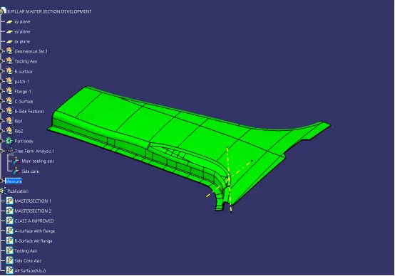
-The Tree Structure Are Classified And The Important Features Are Published And The Operations Are Renamed And Classified Into Geometric Subset Shown Below.
Conclusion
Thus a Tooling Axis Is Created And a Open Aesthetic Class A Surface Is Developed Into a Closed Surface With All Plastic Design Rules And a Final Part Body Is Created Out Of It In Catia Surface Work Bench. The Design Is Then Validated With Master Section And Understood The Use Of Master Section Development In Product Design Through Development Of B Pillar Cover Used In The Car Interiors.