Week-7 Challenge: DC Motor Control
1. Run MATLAB demo ‘Speed control of a DC motor using BJT H-bridge’. Modify the model such that armature current doesn’t shoot up when motor changes direction from forward to reverse.
one can change the direction and speed of mini DC motor using very simple circuit built using readily and easily available handy components. First we will see how we can change the direction of motor and then we will see how we can vary the speed of DC motor. Then I will explain very simple DC motor controller circuit that changes direction as well as varies the speed of DC motor. So let us start.
Tell me how to change direction of rotation of DC motor?
It is very simple. Most of mini DC motors have two terminals because they are series type (armature and field windings are connected in series) DC motors.
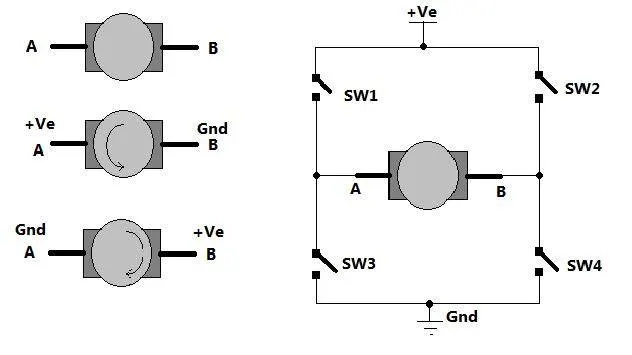
two terminals ‘A’ and ‘B’ of DC motor. Now if we connect terminal A with +Ve supply and terminal B with –Ve supply or ground the current will flow from motor from A to B and motor will rotate in one direction – say clockwise (CW) or forward direction. Now as shown in second figure we change the supply terminals. Now B is connected with +Ve and A is connected to ground. The current will flow from motor from B to A and motor will rotate in other direction (counter clockwise – CCW or reverse).
So next question is how to give reversible supply to motor?
The arrangement is shown in right side of figure. Four switches are connected in between +Ve supply and ground and DC motor is connected in between two switches as shown. Such circuit arrangement is known as H-bridge because it looks like letter ‘H’ (H-bridge circuits are most widely used in DC motor drivers). Let us see how it gives reverse supply to motor.
If SW1 and SW4 are pressed simultaneously then current will flow from +Ve – SW1 – A – B – SW4 – Gnd. So motor will rotate in one direction. Open (release) SW1 and SW4 to stop motor. Now if SW2 and SW3 are pressed current will flow from +Ve – SW2 – B – A – SW3 – Gnd. So motor gets reverse supply and it will rotate in another direction.
care has to be taken that SW1 and SW3 or SW2 and SW4 must not be pressed simultaneously otherwise it will short circuit the supply.
Circuit Diagram of H-Bridge built by transistor for controlling DC motor speed and rotation
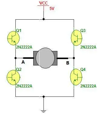
Motor can be rotated forward and reverse using 4 transistors only.
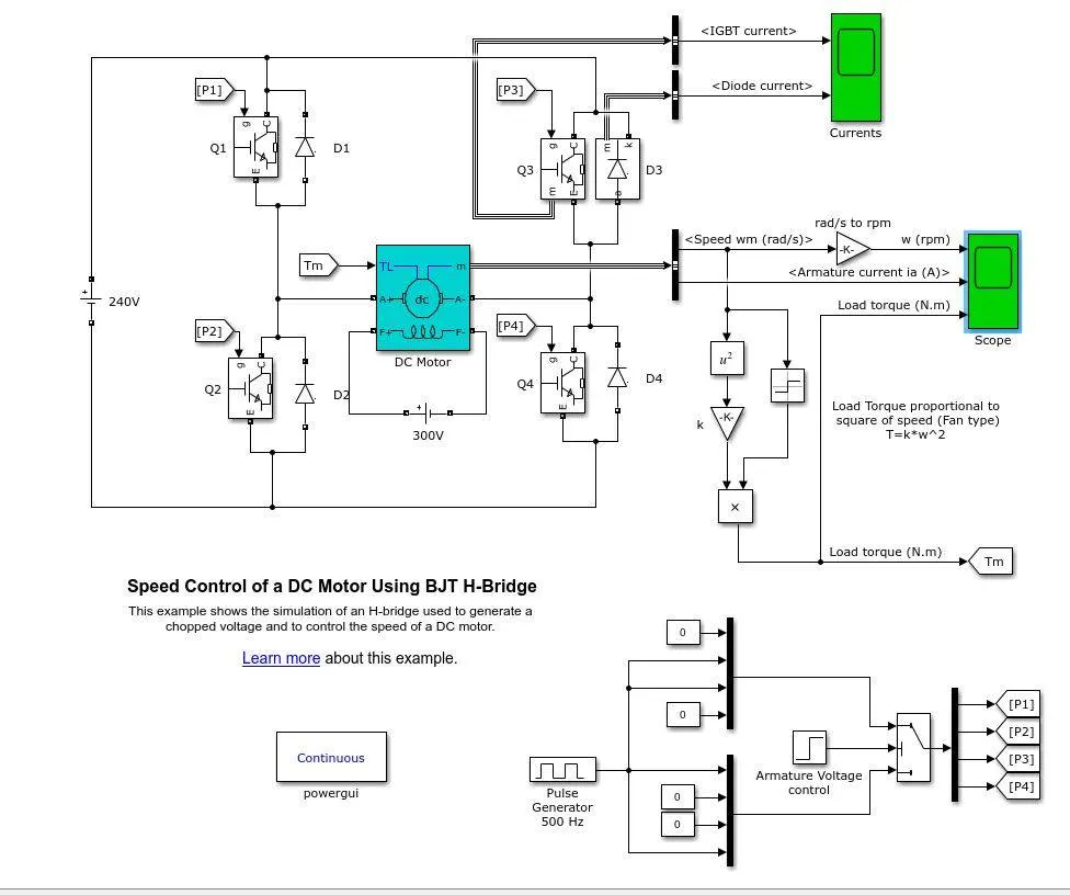
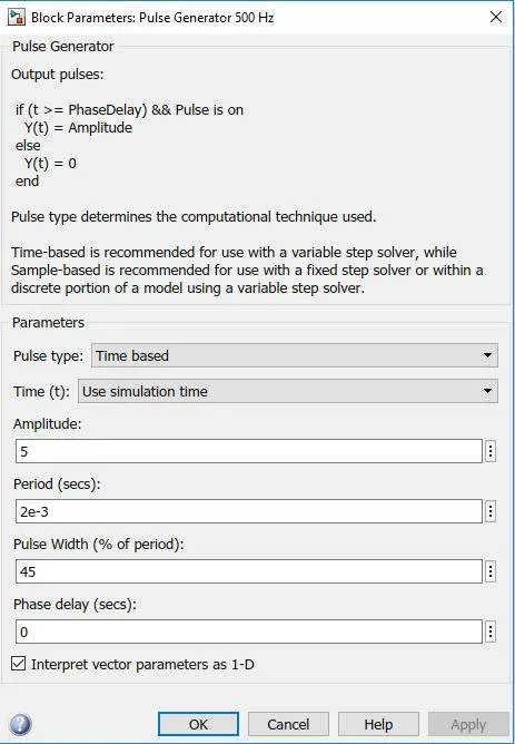
Now let us move to vary the speed of DC motor. The DC motor speed varies as applied input voltage varies. As you increase applied input voltage the speed will increase and vice versa. Applying max rated voltage will rotate motor at full speed, do not apply more than max rated voltage to motor otherwise motor windings may get burnt.
One of the very popular methods for generating variable DC voltage is pulse width modulation (PWM).
Pulse width modulation means varying the width (duty) of pulse. Width means ON time Ton of pulse. The average output voltage (Vdc or Vavg) is given by equation
Vdc = [Ton / (Ton+Toff)] × Vs
It directly depends upon Ton. As shown in above figure if duty is 50% the average output voltage Vdc is exactly the half of Vs. If duty is increased to 75%, Vdc also increases to 3/4th of Vs and if duty is decreased to 25%, Vdc reduces to 1/4th of Vs. Thus as pulse width varies the average output voltage varies. So we have to apply PWM to DC motor to vary its speed
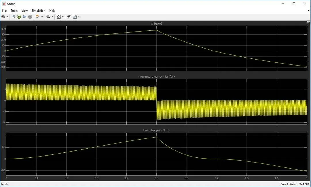
the graph shows the scope of the model.
2.Refer to help section of ‘The Four-Quadrant Chopper DC Drive (DC7) block’. Compare it with H-bridge model.
Description
The armature voltage is provided by an IGBT converter controlled by two PI regulators. The converter is fed by a 515 V DC bus obtained by rectification of a 380 V AC 50 Hz voltage source. In order to limit the DC bus voltage during dynamic braking mode, a braking chopper has been added between the diode rectifier and the DC7 block.
The first regulator is a speed regulator, followed by a current regulator. The speed regulator outputs the armature current reference (in p.u.) used by the current controller in order to obtain the electromagnetic torque needed to reach the desired speed. The speed reference change rate follows acceleration and deceleration ramps in order to avoid sudden reference changes that could cause armature over-current and destabilize the system. The current regulator controls the armature current by computing the appropriate duty ratios of the 5 kHz pulses of the four IGBT devices (Pulse Width Modulation). For proper system behavior, the instantaneous pulse values of IGBT devices 1 and 4 are opposite to those of IGBT devices 2 and 3. This generates the average armature voltage needed to obtain the desired armature current. In order to limit the amplitude of the current oscillations, a smoothing inductance is placed in series with the armature circuit.
How to model it for an Electric vehicle
The energy source of an EV is a battery or fuel cell. Let’s take the case of a battery.
So the model can be modified with an input of a battery from the Simulink Library Browser.
Modify the energy source at the input side
You can take a generic battery model and configure it by referring to any datasheet sheet related to an EV vehicle battery model.
Otherwise the easy option is to use a simple DC source as your energy source and give the appropriate voltage value for an EV. The scope results vary in both cases from each other
- The vehicle should have a reference speed
Give any driving cycle input replacing the Step signal block. You can prepare your own drive cycle data and import it to this model also.
Next let's take the vehicle load characteristics for the relating Torque and Speed of the vehicle. (You can take the vehicle characteristics equation from Challenge 6, question 2 for convenience)
Linear load torque block can be replaced with a subsystem model according to the load characteristics given by
- Make a subsystem for the vehicle load characteristic equation.
- Change the simulation time with respect to your drive cycle data.
- Change the sampling time.
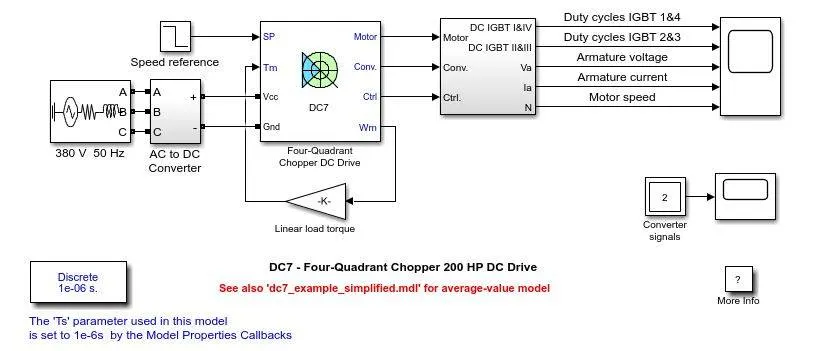
3. Make a suitable EV model using DC7 block and make result report.
- The first regulator is a speed regulator, followed by a current regulator. The speed regulator outputs the armature current reference (in p.u.) used by the current controller in order to obtain the electromagnetic torque needed to reach the desired speed.
- The speed reference change rate follows acceleration and deceleration ramps in order to avoid sudden reference changes that could cause armature over-current and destabilize the system.
- The current regulator controls the armature current by computing the appropriate duty ratios of the 5 kHz pulses of the four IGBT devices (Pulse Width Modulation).
- For proper system behavior, the instantaneous pulse values of IGBT devices 1 and 4 are opposite to those of IGBT devices 2 and 3. This generates the average armature voltage needed to obtain the desired armature current.
- In order to limit the amplitude of the current oscillations, a smoothing inductance is placed in series with the armature circuit.
-
Simulation
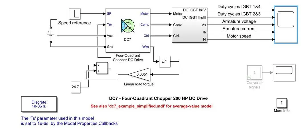
- We need a DC supply that would simulate the EV battery pack, for this we will use a DC energy source.
- For reference speed, we need to give the input of our drive cycle for the PI controller to evaluate the current and voltage inputs for the motor.
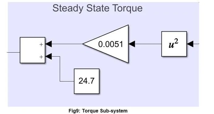
- For the mechanical Torque input, we will be using the Steady state operating conditions to obtain the torque which needs to be provided by the motor for the EV to operate.
- We will be using the equation T_m=24.7+0.0051ω^2
- This equation represents the steady state operating Torque.
- We will be making a subsystem of the blocks representing this equation.
- For the simulation time we need to provide appropriate time according to our driving cycle inputs.
- SIMULATION MODEL
Torque Block:
discussion:
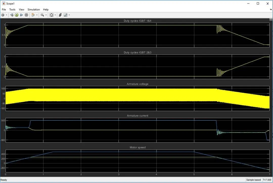
- We have 4 parameters being displayed in the output here; they are Current in the IGBT 1&4 and current in IGBT 2&3, along with that we have the Armature Voltage, Armature Current and Motor Speed.
- We can observe that the Motor operates in Sync with the drive cycle reference speed and is able to produce appropriate outputs.
- Coming to the duty cycles in the IGBT we can observe that the duty cycles vary according to the reference speed, in 1&4 we see a increase when there is a rise in speed while we see a decline in 2&3 during the same.
- We can observe the same kind of change in the current, with the sudden reduction in speed, we see a dip in current and a increase in IGBT 2&3 duty cycle.
CONCLUSION: Working understanding of power controllers in MATLAB Simulink is developed for BJT H Bridge and DC7 4 Quadrant DC Motor Chopper model.