Week 11 - Final project
AIM:
To design and develop vehicle interior door trim using Catia V5 with given class A surface along with Master section. Also create the Side Attachment features as per design rules.
OBJECTIVE:
- To create thickened part using master section for reference
- To create the mounting features as per design guidelines in the industry and with master sections
- To perform Draft analysis & Tooling analysis
INTRODUCTION:
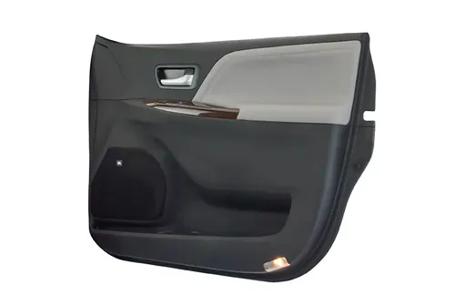
The door panel is the interface between the interior of the car and the inner workings of the door. Generally the door panel is divided into parts for easy designing like armrest, map pocket, lower substrate. These require one of the toughest requirements among the interior parts of the car. This should be designed to withstand the load while being less than 2mm in thickness and also to protect the occupants during collisions.
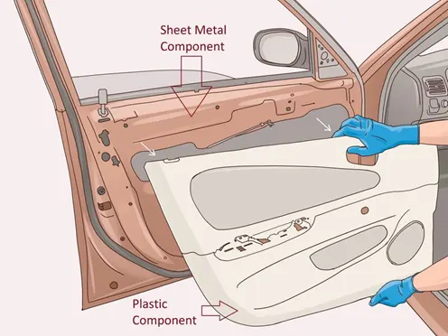
Door currently has an inner full width panel consisting of electric windows, central locking system and speakers. These panels typically consist of a foamed core covered with either textiles or plastics.
METHODOLOGY:
Creating the Tooling Axis
The tooling direction is used to find the direction in which the part is removed from the core and cavity. The draft angle should be positive to the tooling axis to manufacture the component easily. The step by step procedure of creating the tooling axis is given below.
Step: 1
Creating the tooling axis for Map Pocket by creating a point on surfaces respectively to the 0 value. It automatically creates a mid surface and generates the line to the direction of y axis.
Step: 2
Creating the tooling axis for Lower Map Pocket by creating a point on surfaces respectively to the 0 value. It automatically creates a mid surface and generates the line to the direction of y axis.
Step: 3
Creating the tooling axis for Lower Substrate by creating a point on surfaces respectively to the 0 value. It automatically creates a mid surface and generates the line to the direction of y axis.
Step: 4
Creating the tooling axis for Arm Rest by creating a point on surfaces respectively with the Axis system. Now create the intersection for the Z-Y AND Z-X axis respectively based on the point. creating the bisecting line to the both intersections and creating bisect for those lines. Hence we get the final tooling axis for the Arm rest.
Step: 5
Creating the sliding tooling axis for the arm rest by extracting the side walls of the surface. Creating the point on the surface with the axis system, here y axis is considered as removal direction, hence line is created to the y axis.
Creating the B surface.
Creating the B-SURFACE by extracting the class A surface, by each surface separately, it is offset to a certain distance, making a point on the master section to get the intersection as shown below.
Finally we achieved the B class surface by extracting and offset the Class A surfaces.
Creation of C Surfaces:
Step: 1
Extract the boundary of the Class A surface and it is made into smooth curves to sweep the curves by using support surfaces to the 90 degree respectively.
Step: 2
Once the all surfaces joined together it extrapolated to a certain distance to trim with A Class surface to C surface. Finally we created a Class C surface.
Making the Final plastic Component:
To make the final component the Class C surface is trimmed with the Class B surface, the output will get the component with 2 mm thickness of surface and it is converted into a solid body using the insert body option in part design.
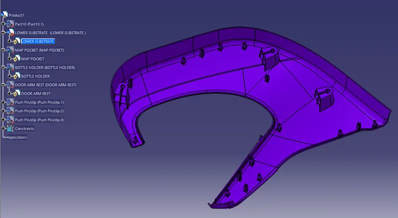
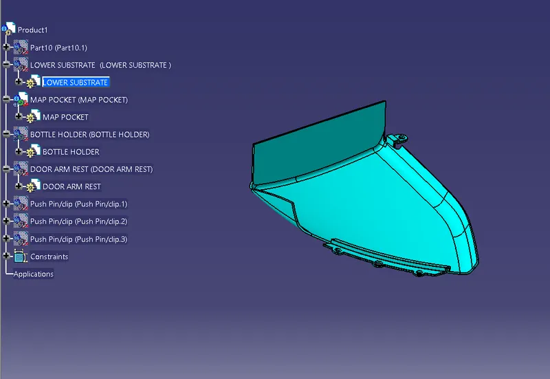
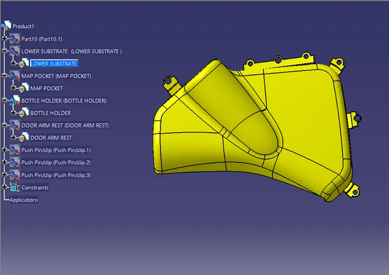
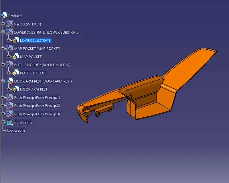
Creation of Attachment Feature to the Door Trim:
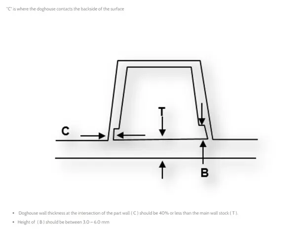
Dog house is an engineering feature used in plastic trim design. Dog houses are used as supporting features. Sometimes other engineering features like snaps; locators etc. are mounted on them to increase their strength. Dog houses are subjected to draft analysis to prevent breakage of the component during ejection from mould cavity. Dog house and other engineering components are built on B-surface
Step: 1
Creating the sketch by extracting the class A surface, by each surface separately, a point and axis system created sim.
Step: 2
The extruded surface is extrapolated, the extract surface from Class A has been offset to make the side wall surface of the dog house by trimming it. multaneously on the surface.
Step: 3
The extruded surface is converted into solid by thickening the surface for 2mm and it is extrapolated and to make close body it is split into equal distance It is drafted for 0.5 deg perpendicular to the sidling axis as shown below. The edges were chamfered for 5mm to 45 Degree.
Step: 4
The undercut has been made by an extrapolated surface and it is offset to the minimal value and it is trimmed to get a perfect undercut. To get the proper clearance for removal of the component is drafted for 0.5 at the undercut area and it is chamfered for 1 mm to 38 deg
Step: 4
It is union trimmed to lower substrate and it is filleted for radius 2.5mm of smooth edges
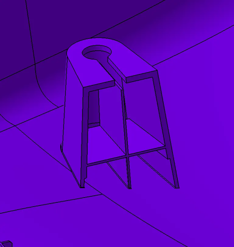
DOG HOUSE
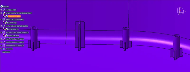
Creating the Heat Stake:
Heat staking is a pulsed – heat process to join two or more parts out of which one at least is made of plastic . The plastic is to deform the plastic material using the heat and foam at a set process time. The bond is made by partially deforming the plastic part in order to fix the other. Heat stakes make it easy to bond metal to plastic and are commonly used in high volume and low cost applications such as Automotive, IT and consumer appliances.
Step: 1
Creating the sketch by extracting the class A surface, by each surface separately, a point and axis system created simultaneously on the surface. Using positioned sketches.
Step: 2
The sketch feature is then extracted to the required dimension. And it is drafted for the 0.5 deg to the sliding tooling axis, it is filleted for radius 0.25 of smooth edges
The support rib was created, where the flange will come and sit to get arrested to the heat stake.
Creating the Push Pin Clip:
Step: 1
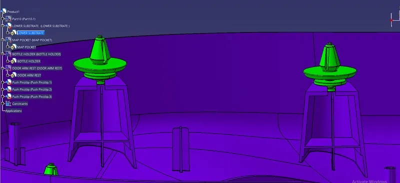
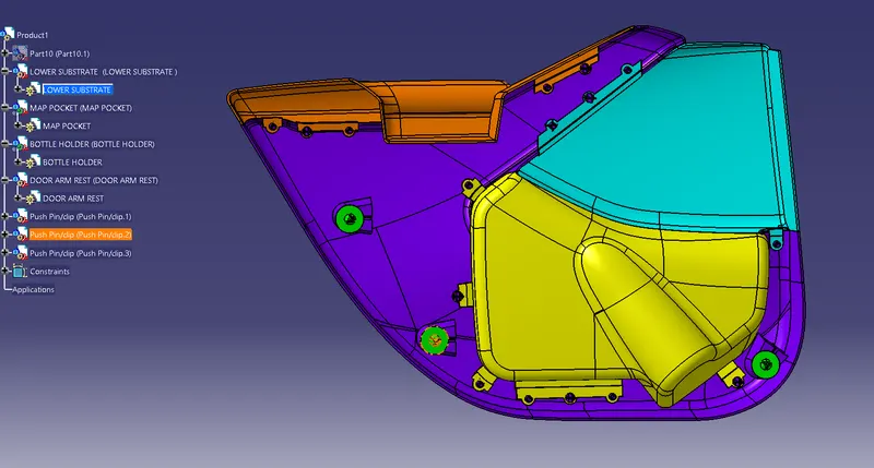
The push pin clip has been sketched for the required dimension. It is revolved to make solid component It is mounted on the top of Dog House to the lower substrate assembled body
Performing Draft Analysis:
The Draft Analysis command enables you to detect if the part you drafted will be easily removed. This type of analysis is performed based on colour ranges identifying zones on the analysed component where the deviation from the draft direction at any point, corresponds to specified values. This rule of thumb applies to parts with mold depths of up to 2 inches. At this size, a draft as low as 1½ degrees will allow for an easy, non-damaging release from the mold when the expected shrinkage of the thermoplastic material occurs.
It’s also important to remember that draft angles are just one component of an effectively designed injection molded piece. Design for manufacture is one of the easiest ways to improve the quality and efficiency of your injection molding process, and it never hurts to stay up to speed on all injection molding best practices.
Draft Analysis for Class A surface:
Step: 1
Initially we perform the draft analysis to class a surface to ensure that we have a good quality surface to make Class B and C surface to achieve the same kind of quality surface. First we have to set the compass on the main tooling axis to get the direction of the core and part moves along.
Step: 2
Once the compass is locked in the axis, directly click on the surface it will appear the quality of the draft surface whether it is passed or failed. Here the draft angle is given as 3 degrees. Hence we achieved a green colour on the top surface. Hence it accepts the draft angle for the surface, so we build good quality components.
Step: 3
Now we check the colour variant scale to ensure the maximum and minimum area draft angle is achieved by displaying green, red and blue colour respectively. If the surface appears red in colour while analysing it is not accepted.
Step: 4
We can check the angle of draft given to surface by using draft tool analysis just point the over the surface where we have check angle of given draft to the component.
Draft analysis on Door Trim Solid Body with attachment features:
Step: 1
First we have to set the compass on the main tooling axis to get the direction of the core and part moves along.
Here the draft angle is given as 3 degrees. Hence we achieved a green colour on the top surface. Hence it accepts the draft angle for the surface, so we build good quality components.
Now we check the colour variant scale to ensure the maximum and minimum area draft angle is achieved by displaying green, red and blue colour respectively. If the surface appears red in colour while analysing it is not accepted.
We can check the angle of draft given to surface by using draft tool analysis just point the over the surface where we have check angle of given draft to the component
Step: 2
A sliding axis for the Arm rest component has been done separately by using sliding tooling axis
Step: 3
For Attachment Features the draft angle is applied for 0.5 deg and its analyzed using the sliding tooling axis
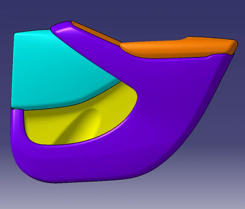
Front View :
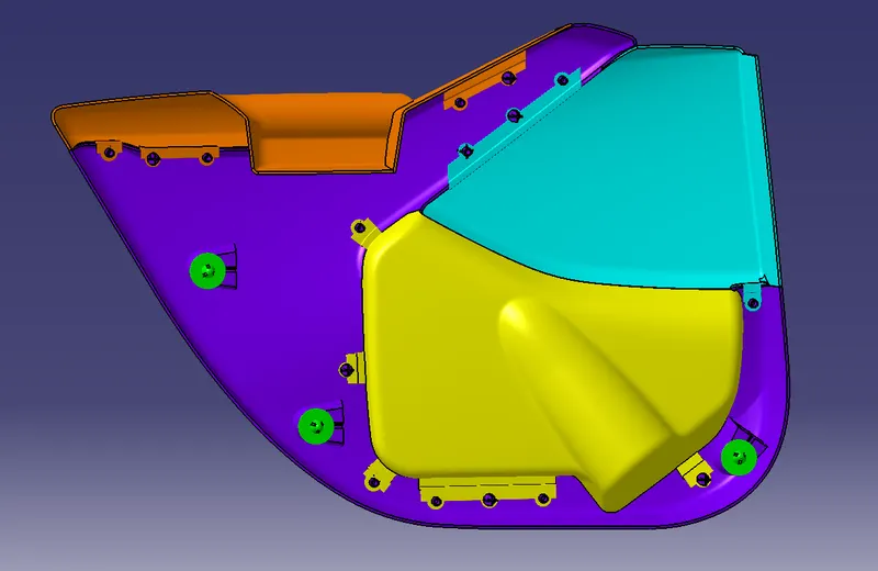
Back View along with attachment features:
Conclusion:
Creation of the car interior door trim is designed using the given class A surface as the input and Class B and C surface created with the help of Class A surface. By using the given master section attachment features I.e. Heat stakes, Flanges, Dog House and Push Clips are created using the design rules. The draft analysis has been performed to analyze the draft of the component to manufacture easily applying draft to the surface by 3 degree and 0.5 degree to the attachment features. With all data and reports we can conclude that draft analysis is very important to design any plastic component to mold the plastic easily. The analysis will verify that all surfaces are favorable for being pulled from a cavity. It may also highlight or give insight to defect areas.