Week 9 - Project 1 - Door Trim Lower with Engineering Features
Tooling Axis creation and Draft Analysis on a given Class-A Surface of Door Trim and Create the Heat Stakes and the locators considering the design rules
Aim:
The Objective of the project is to do Draft Analysis by Creating the tooling direction for given Class A Surface. and Thickness of the component is 2.5mm and Creating the Heat Stakes and the locators considering the design rules.
Introduction:
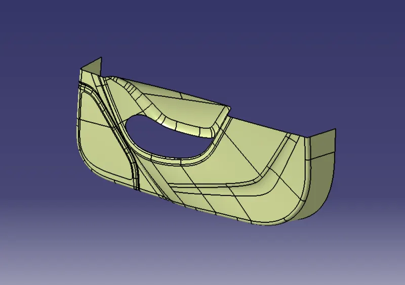
The Draft Analysis command enables you to detect if the part you drafted will be easily removed. This type of analysis is performed based on colour ranges identifying zones on the analyzed element where the deviation from the draft direction at any point, corresponds to specified values.
Tooling direction is the main consideration for plastic part and mould parts because it defines the movement of the mould part and the possibility of the plastic part coming out from the mould part (Core and Cavity).
Tooling Direction:
- Tooling direction is known as primary direction. In Molding, machine arrangement is given to open the mould along a direction which is known as Tooling Direction. In other words. The mould is built from two separate halves (Core and Cavity) and tooling direction basically defines the direction of mould pulls apart.
Procedure for Creating Tooling Axis:
- First, the given styling surface was imported into CATIA and checked for irregularities by using Join, Boundary and Disassemble option.
- Then Make a point on the surface and create line for Tooling Axis. Here i did't used bisecting lines.
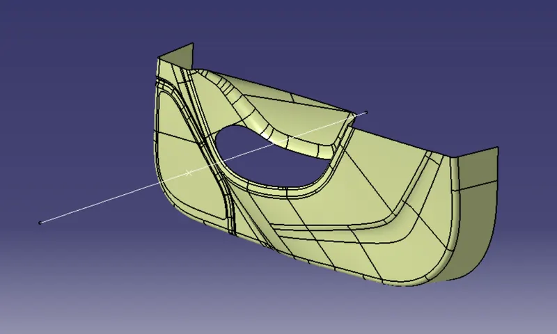
Publications:
The tooling axis and class-A surface were published for further easy reference, from Tools – Publications.
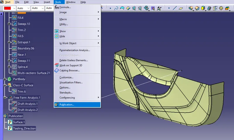
Performing Draft Analysis:
- For plastic parts, the nominal angle value for draft analysis is 3 degree but even a 0.5-degree angle can be created for sub-assemblies like ribs and slots. (For Sheet Metal 7 degree angle is the nominal value)
- Insert – Analysis – Feature Draft Analysis
- Draft analysis was carried out by pulling the compass to the tooling axis and an inverse draft axis was carried out if required.
- After setting the compass over the tooling axis the compass must be locked to a specific direction.
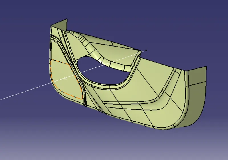
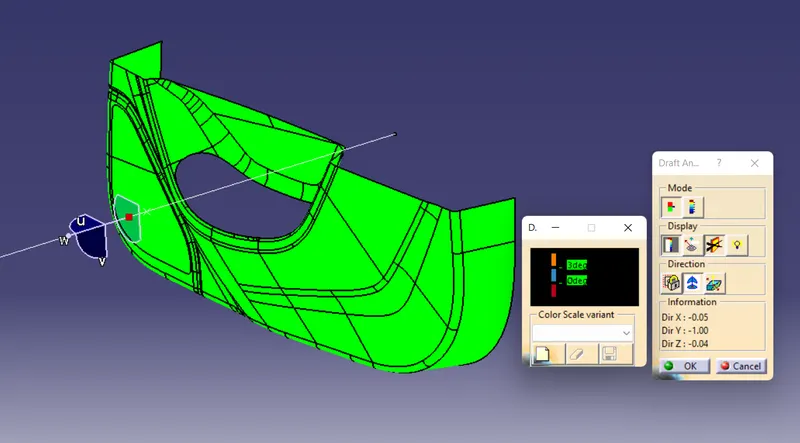
- If the surface was in green then the model passes or else further operations need to be carried out.
- By using full analysis mode detailed analysis can be carried out for complicated assemblies.
- By using the analysis under the running point complicated parts and surface were checked in detail.
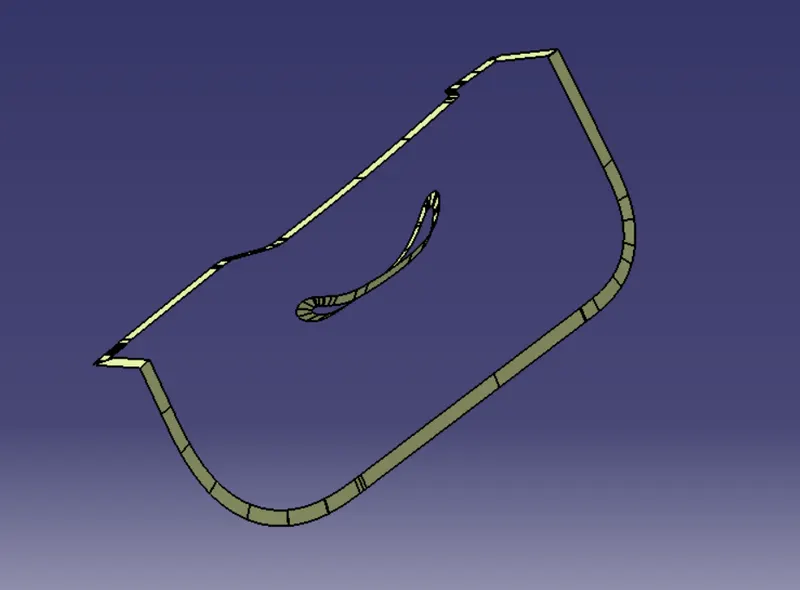
Class C Surface
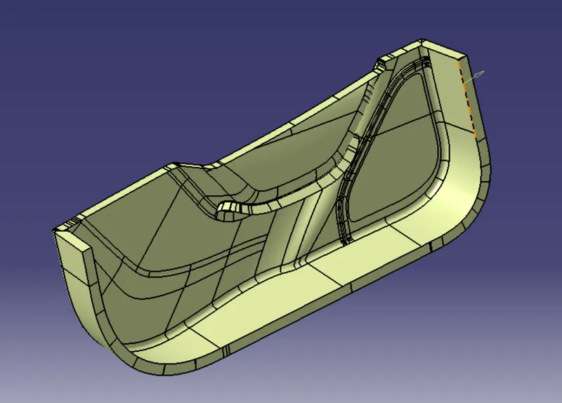
Joining Class A Surface and Class C Surface
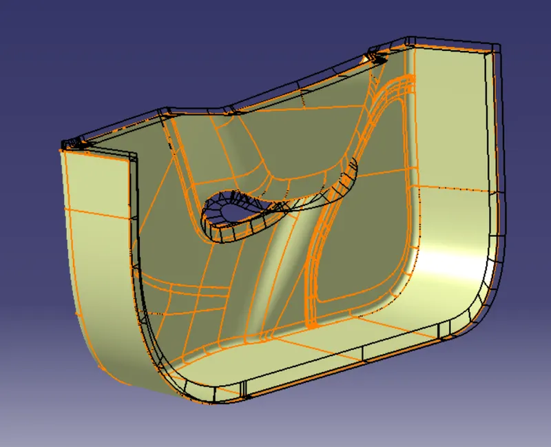
Then trim the class-B surface to join (A+C) this will make sure that we get a closed surface. We can check it using the boundary tool, if it gives an error that means that the component is closed.
Then We go to the part design workbench and use to closed surface tool to create a solid body.
hence, we created our final plastic component.
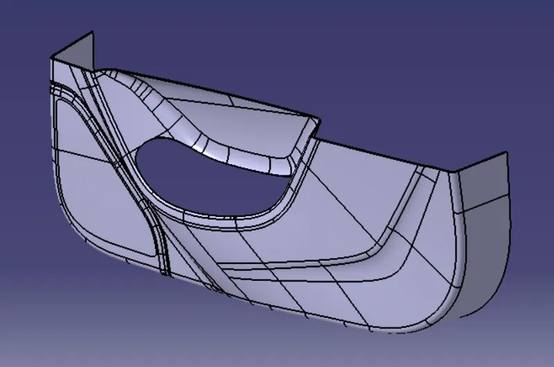
Then will do draft Analysis for clossed or solid part. for Draft Analysis go to insert then analysis in that select draft analysis.
ther have to move the compass to tooling Axis then select the component.
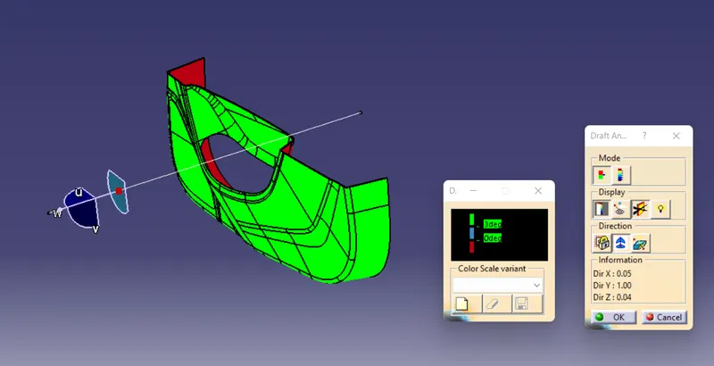
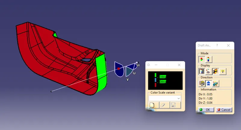
Creating the Heat Stakes and the locators considering the design rules
Heat Stackes:
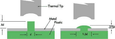
Heat staking also known as thermoplastic staking is the process of joining two dissimilar materials together. In heat staking, we use local heating and cooling to raise the temperature of plastic components and allow plastic reforming to be carried out.
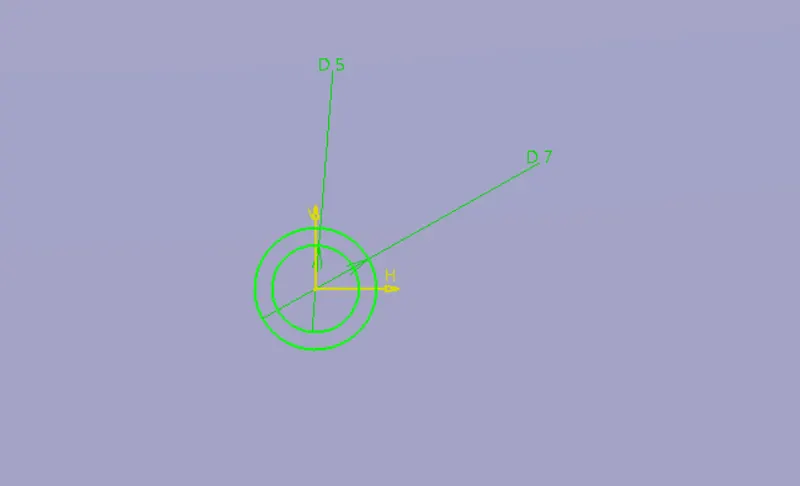
Sketch
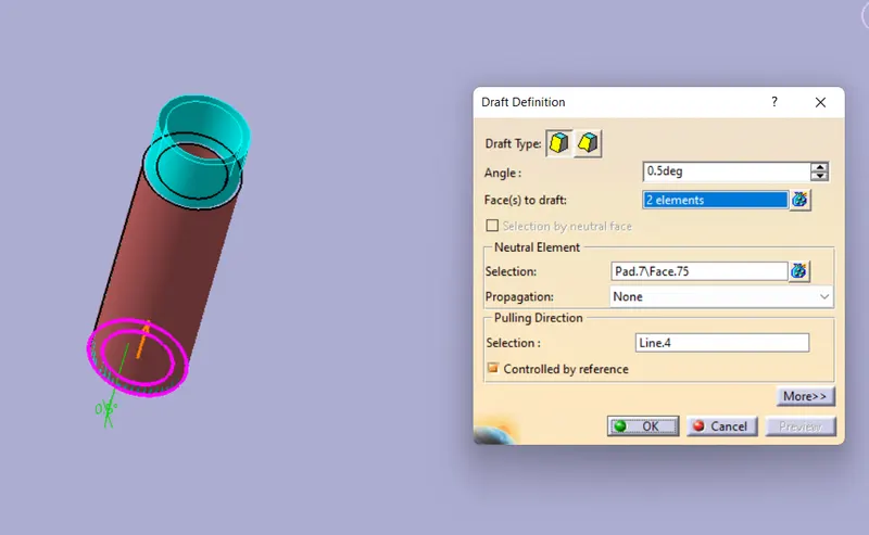
0.5 degree Draft Angle
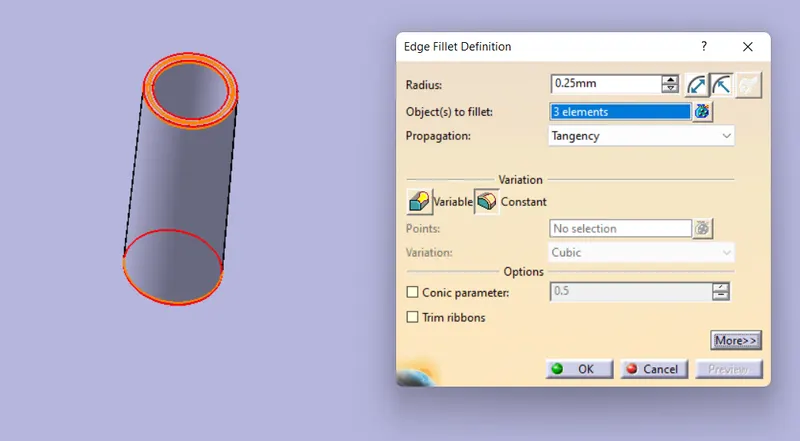
0.25mm Fillet Radius
Fillet is applied to the faces. As per the design rule, the fillet can be 0.25 mm. These heat stakes will enter the mating component and using a heat staking machine these heat stakes are melted and cooled. When cooled this will get hardened and the two components will stick together. Thus all degrees of freedom are arrested.
2WAY AND 4-WAY LOCATORS:
A 2-way locating pin restricts motion along 1 axis (or 2 degrees of Freedom), like a round pin in a slot. Likewise, a 4-way pin restricts 4 degrees of freedom along 2 axes. A round locating pin located concentrically in a hole is a common application of a 4-way pin and helps to further secure the piece. For restricting that degree of freedom we will be using the locators According to the requirements of the fixation we place locators on the component.
4 Way Locators
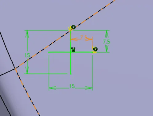
Sketches
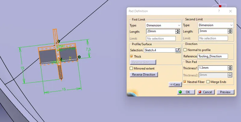
Given 1.3mm Thickness for 4 way locator.
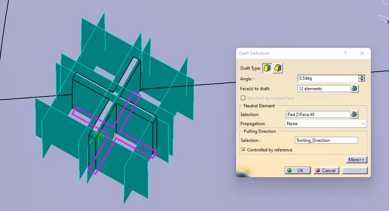
Given Draft angle 0.5 degree.
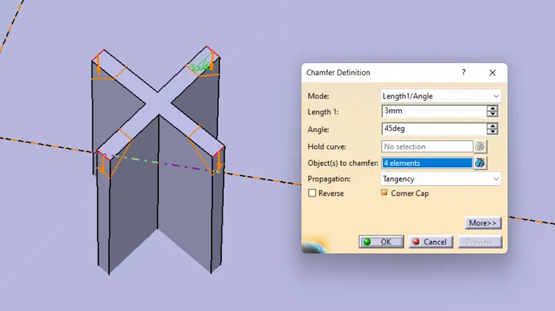
Chamfer for 4 way locator is 3mm length and 45deg angle given.
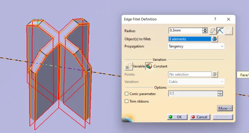
0.3mm Fillet radius given.
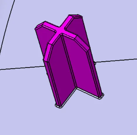
2 Way Locator:
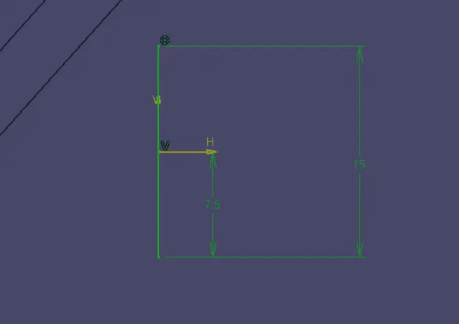
Sketch
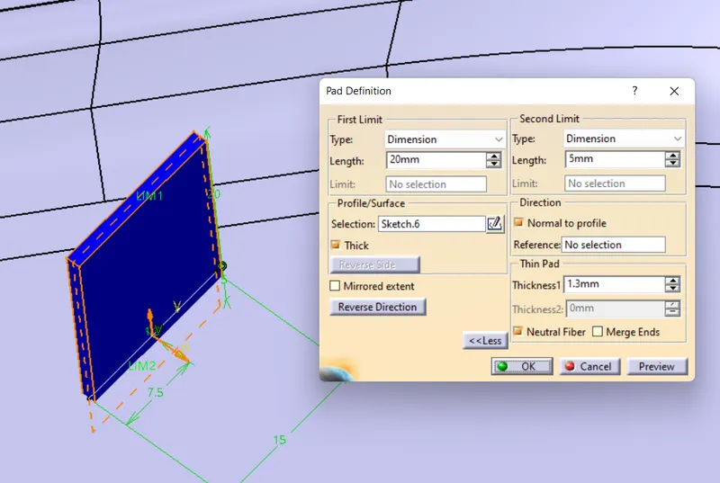
1.3mm Thickness and Pad for 20mm.
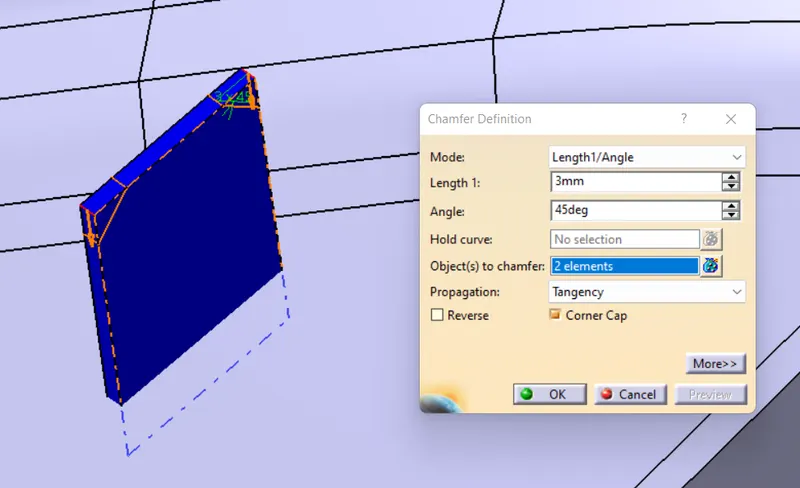
Chamfer for 2 way locator length is 3mm and angle is 45 deg.
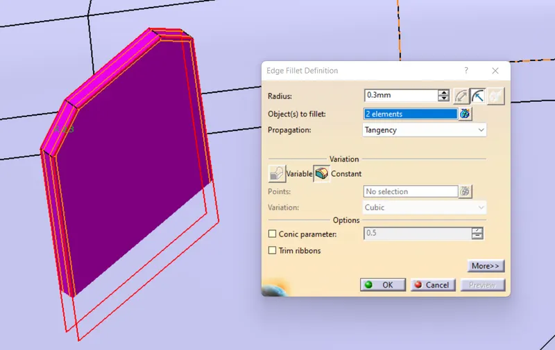
0.3mm Fillet Radius are given.
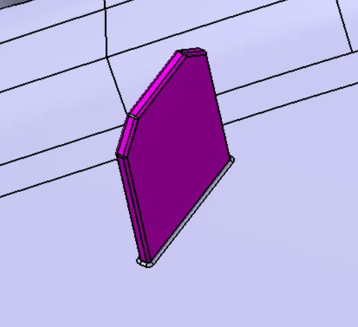
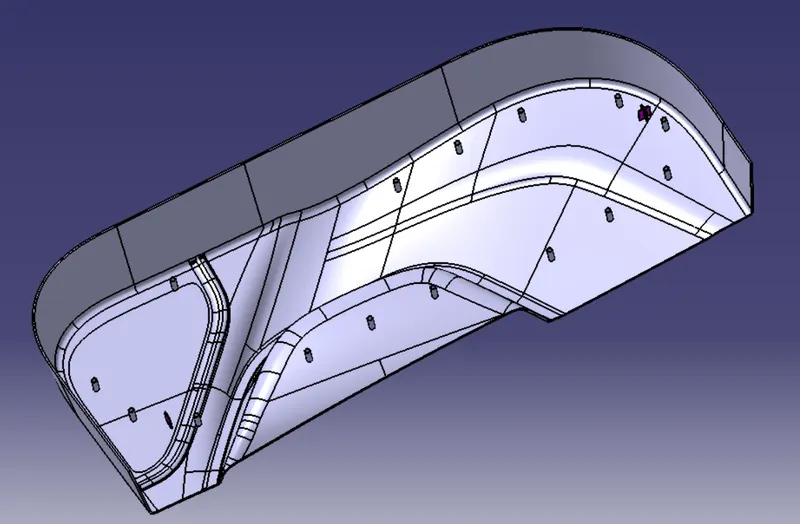
Engineering features locators and heat stakes:
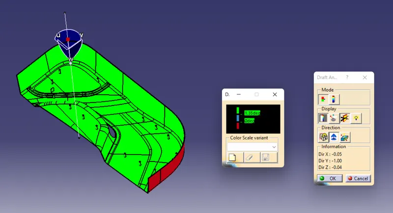
DRAFT ANALYSIS OF THE FINAL COMPONENT
Draft analysis is an operation that is performed to know the draft angles of the surfaces concerning the tooling direction.The minimum feasible draft angle for this design is 3 degrees. Generally for plastic components, a minimum draft angle that can be achieved is 0.5 degrees
- Go to the Insert menu and select the Analysis option.
- Select Feature Draft Analysis.
- Select the Material option and select the surface.
- Drag the compass and place it on the tooling axis.
- click on the surface and see that the surface is within the permissible limit of the draft values.
- Click on Okay.
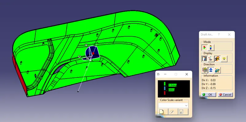
Front View:
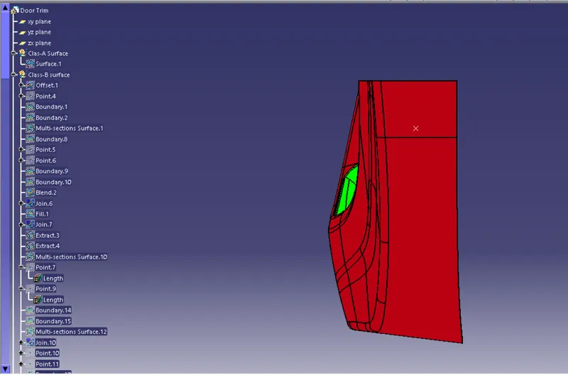
Side View:
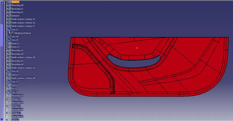
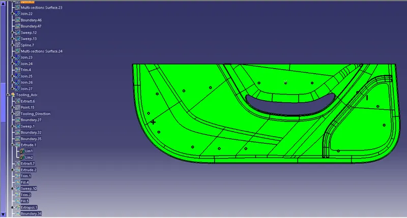
Top View:
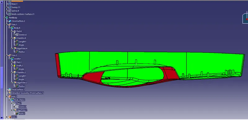
Bottom View:
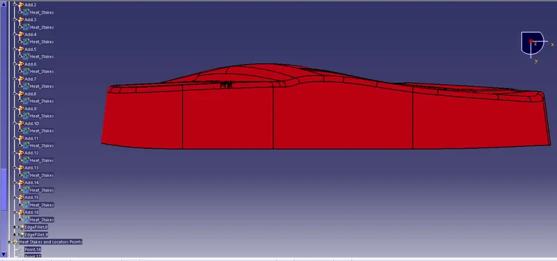
Isometric View:
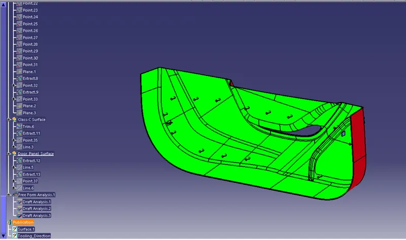
Conclusion:
The draft anaysis and the Heat Stakers and 4 way & 2 way locators are created successfully.