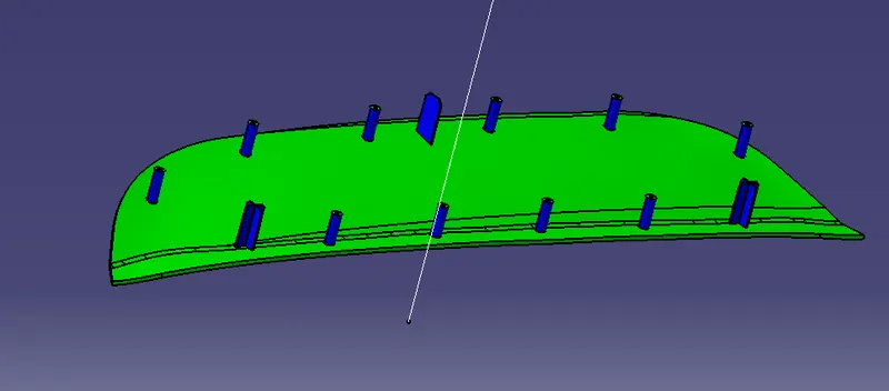
Vehicle Door Applique Design with Engineering Features
DOOR APPLIQUE DESIGN WITH ENGINEERING FEATURE
AIM:
To create a door applique and door attachment from the given Class-A surfaces and to create engineering Features to fit the component in the main surface.`
Thus the Door Applique id developed by using the given Class-A surface . 2 and 4 Way locators have been designed in order to fix the position of the applique with the mating door panel and also designed the heat stakes which used to fix the component with the mating panel by melting.
Clase-A surface
- This class-A is an Aesthetic surface, only the styling team makes this surface, This Class-A surface making ALIAS Software. This Class-A Surface is the input surface For Designer, from this surface, we start to work From this surface, we start to create the Classe-B surface & Classe-C surface. This Class-A surface comes customer view side so on this side no one engineering feature available.
- Styling team using clay for making A-surface then use scanning device (light scanner to capture precise 3-D images) Scanning all data convert CAD data.
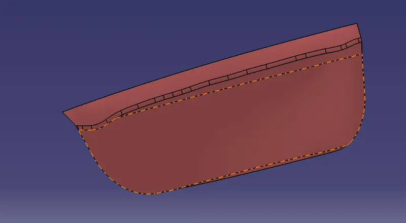
Clase-A surface
Class-B Surface
This Class-B Surface is Offset from Class-A Surface. Offset B-Surface maximum 3mm. Depends on the customer this 3mm value will be change, this Class-B surface on we crate engineering features
Engineering Feature can be created only B-surface. because B-surface is vehicle inner surface people can't see this surface.
Class-C Surface
This C-surface Sweep Along The Boundary From Class-A Surface, the Sweeping Angle is 3deg Respect To the Tooling Axis.
The Stages of the Design Life Cycle are
Concept Sketches:
- Concept sketches are ideas of freehand sketches,
- This hand sketch model is just for a generator concept
- It is usually done with pen and paper and through the painting software.
Class A Creation:
- Then this freehand sketch-based styling team makes a surface, this surface making styling software
Clay Modeling :
- Then Satisfaction for that A-surface, that surface model created one prototype, that prototype surface will be made by clay
- In That clay model, we check the Final surface outlook & aerodynamic condensation like take some other test.
NPD CAD :
This NPD CAD hears engineering work involved hear.
- Tooling Axis
- B Surface Creation
- C Surface Creation
- Closed Body Creation
- Draft Analysis
Tooling Axis
The class-A surface we check to tool direction & Check Draft analysis. these tooling analyses will be clear we go to the next work, suppose the surface will be not clear in draft analysis, this class-A surface forward again styling team tag recreate again because the draft analysis will be not clear. But these case draft analyses will clear Me to go to the next operation.
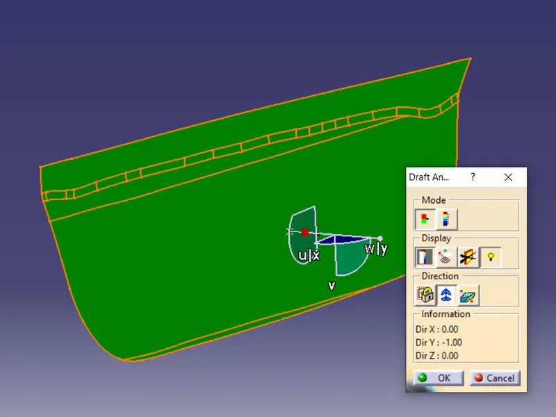
Class-B Surface Creation
This Class-B Surface is Offset from Class-A Surface. Offset B-Surface maximum 3mm. Depends on the customer this 3mm value will be change, this Class-B surface on we crate engineering features
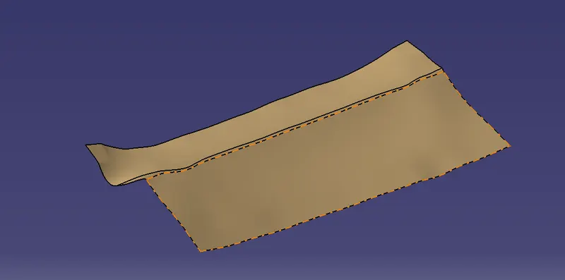
Class-C Surface
This C-surface Sweep Along The Boundary From Class-A Surface, the Sweeping Angle is 3deg Respect To the Tooling Axis.
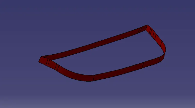
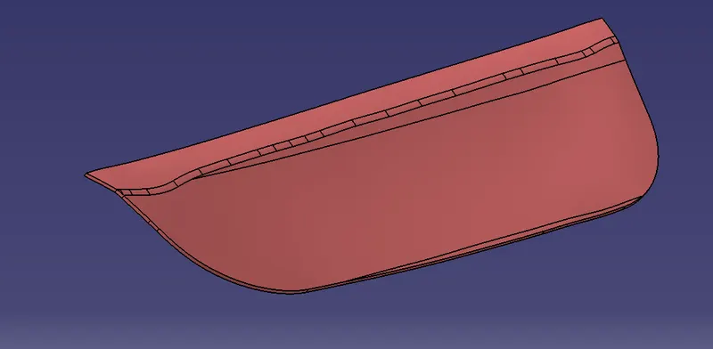
Joint Classe-A, B & C Surface (Closed Body Creation)
After Finishing All Surface Using Trim Option, First Trim Class A, with C-Surface & then Trim With B-Surface. Then Final Step is to Check Any Surface will be open are not, this surface will be closed our model is good. unfortunately, our surface will be open we try to a joint in that tool there is one option merging distance there assignee 0.0003. This 0.0003 is the maximum value don't go to the maximum 0.0003 values.
Engineering feature.
Engineering Features main purpose increase component strength & One component is attached to another component.
In These Project (Door Applique) I used 3-Engineering Features.
i 2-Way Locater
ii 4-Way locater
iii Heat Strikes
2-Way Locater
2-way locating pin restricts motion along 1 axis (or 2 degrees of Freedom), like a round pin in a slot.
4-Way Locater
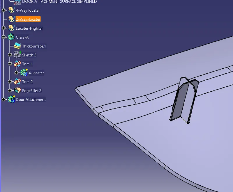
4-way pin restricts 4 degrees of freedom along 2 axes. A round locating pin located concentrically in a hole is a common application of a 4-way pin and helps to further secure the piece.
- Crate sketch for engineering Feature Then Pad normally to profile With tooling Dractation
- Champer
- Fillet
- Union Trim with Main Part-Body
- Asine Fillet On Edge Surface
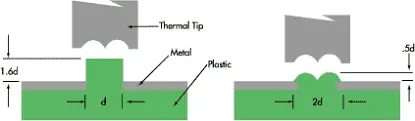
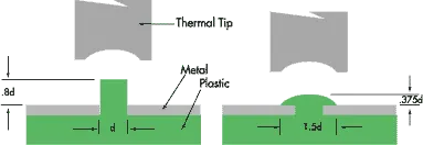
HEAT STACKING
Heat Stacking It used for a permanent fix. if you see the Below picture if understand easily
Most of the industry approach two types of heat stick
1- Hollow Heat stick
2- Solid Heat Stick
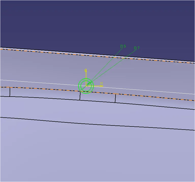
Crate Sketch For Heat Stacking.
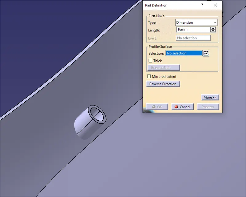
Used Pad tool
Translate Part By using Point to point Translate
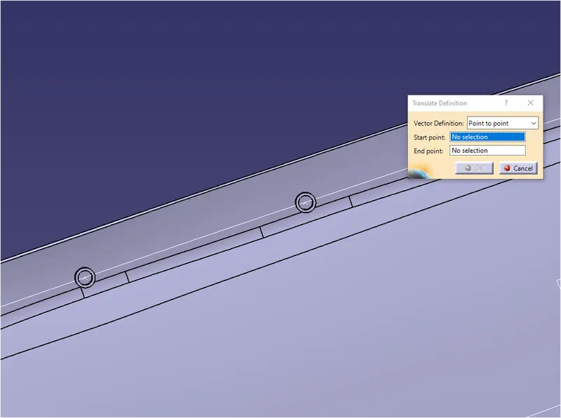
Translate required Place
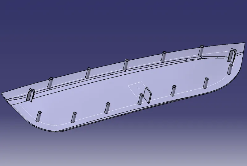
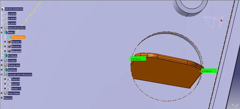
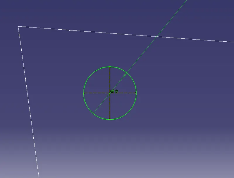
Make Circle for locater locating purpose. locater outer diameter 15mm, make Locater clearance circle is 15.1mm
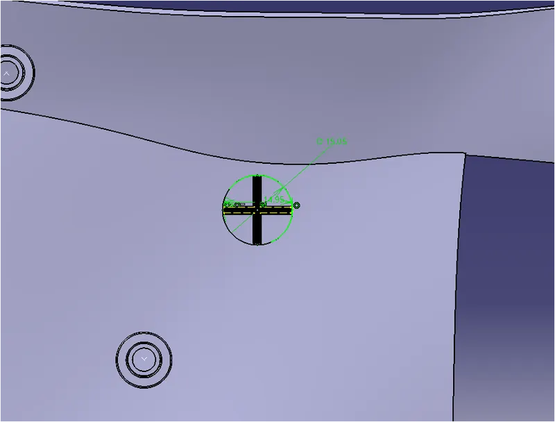
Make Rectangle for 2Way locater clearance hole
Used Boolean Operation within the tree
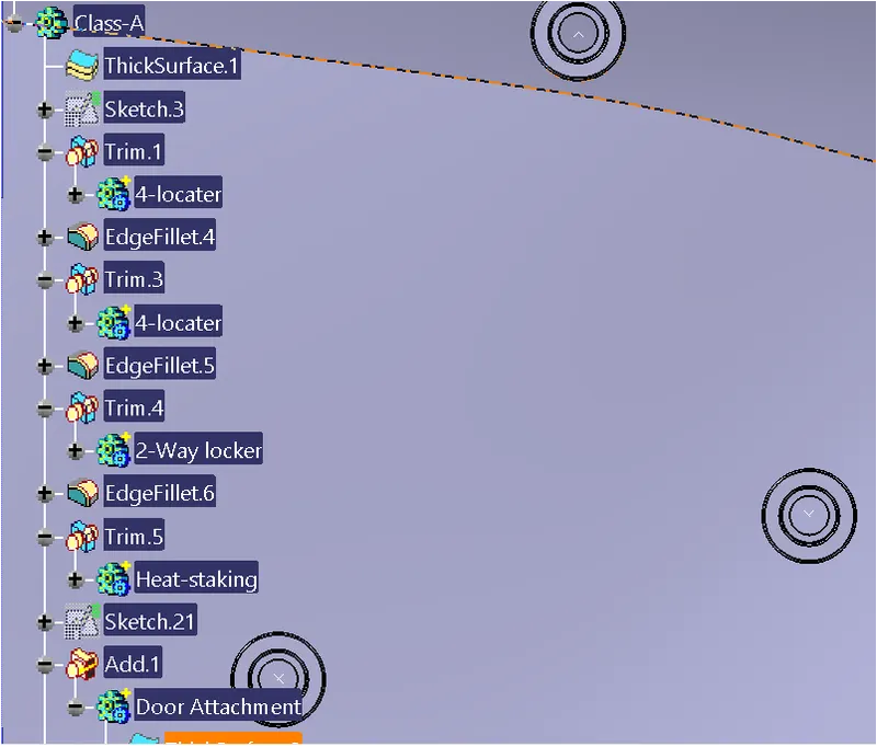
Final Step union trim With
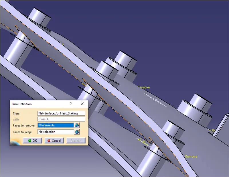
Final output
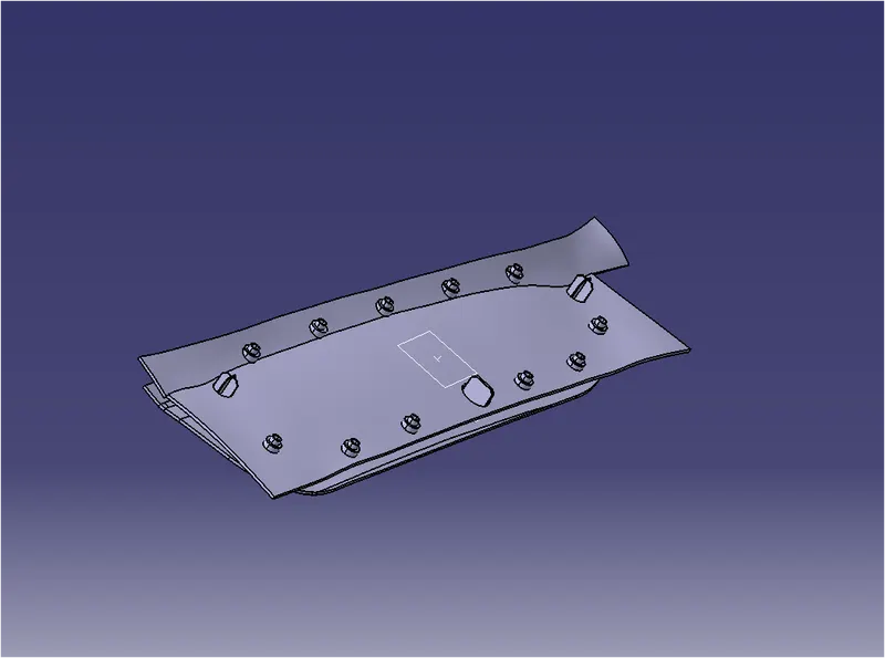
Tooling-Deraction