Vehicle B-PILLAR Surface Design with Engineering Features
B-PILLAR
AIM:
To create a door applique and door attachment from the given Class-A surfaces and to create engineering Features to fit the component in the main surface.
Thus the Door Applique id developed by using the given Class-A surface . 2 and 4 Way locators have been designed in order to fix the position of the applique with the mating door panel and also designed the heat stakes which used to fix the component with the mating panel by melting.
Clase-A surface
This class-A is an Aesthetic surface, only the styling team makes this surface, This Class-A surface making ALIAS Software. This Class-A Surface is the input surface For Designer, from this surface, we start to work From this surface, we start to create the Classe-B surface & Classe-C surface. This Class-A surface comes customer view side so on this side no one engineering feature available.
Import-model first we checking Any open surface Are anything missing in surface properly check every ware.
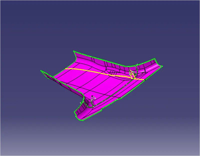
so in this Surface ever thing is good
First open class-A surface we check to tool direction. & Check Draft analysis. these tooling analyses will be clear we go to the next work, suppose the surface will be not clear draft analysis, this surface forward again styling team tag recreate again because the draft analysis will be not clear. But these case draft analyses will clear Me to go to the next operation.
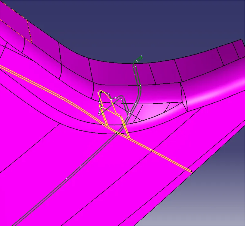
So I take This Engineering Feature. Particularly why I take this Feature Because Engineering Feature All Make on Tooling Axis.
This Engineering feature Based on my tooling Axis mostly My All Surface Will Be Clear.
Crate Tooling Axis. I want Lines on features, So I Extract Those Features. then Crate Line.
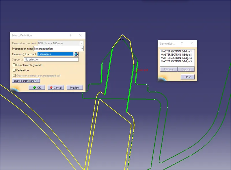
If Now Easly I Crate line on Feature.
Crate line By using Used Line option, Then Finally I Used By-setting Line
Now Crate Tooling Axis
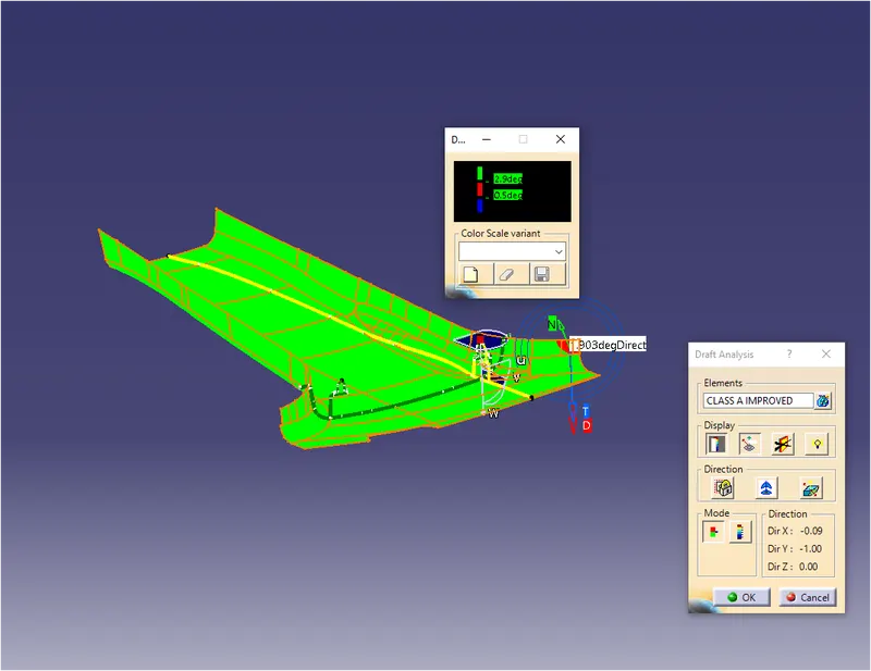
Tolling Axis Done
Corner Surface Only Show in Red Colour. That Surface Not Issue Because That Red Zone Abeow 1.5deg so it's not an issue.
Noe Start Crate B-Surface.
* First Properly Extract A-surface
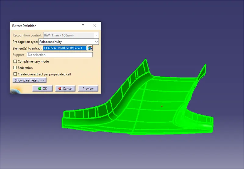
* Extract Surface Off-Set 2mm
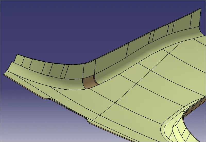
I am Extract a-surface 2mm, But Some Surface Not Extract Properly. Those All Surface Clear Mainualy
I Crate Surface By using Multi-section tool.
First Extract Missing Surface Boundary.
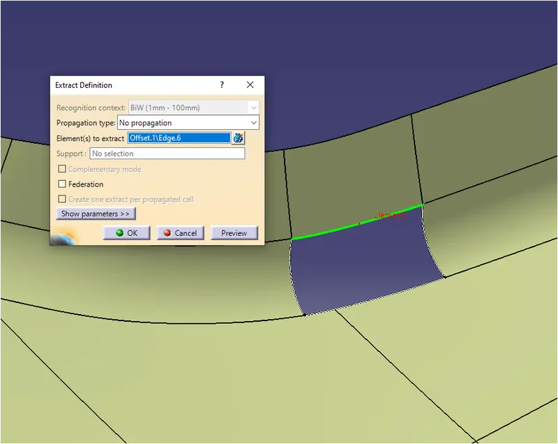
Noe Using Smooth-Curve Tool.
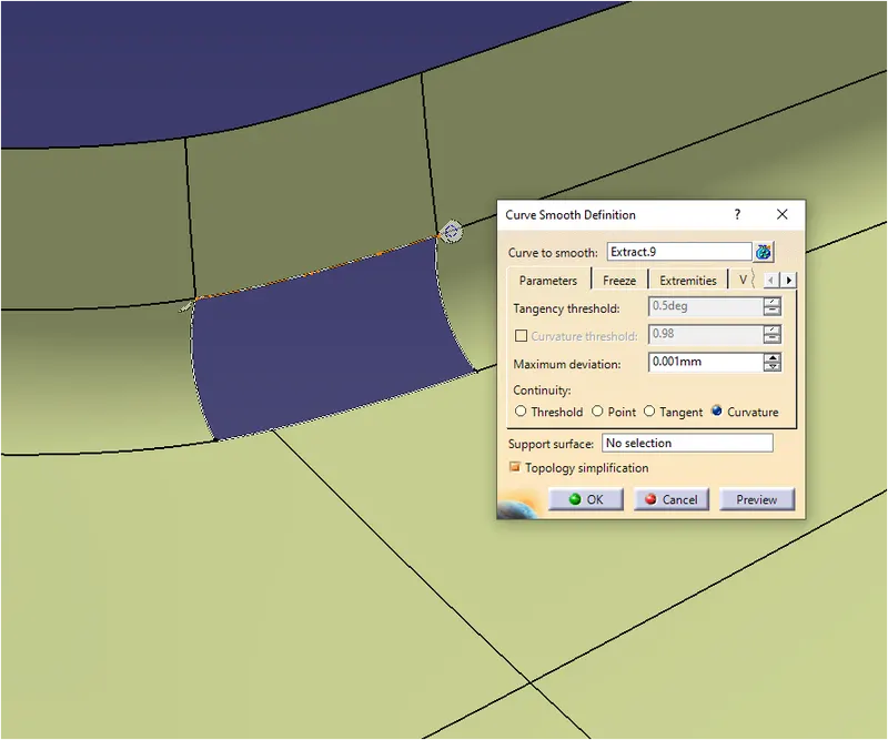
This Smooth Tool is really Helpful For Crating surfaces. Because Using This Tool We Avoid Crate Unnessery Patch line.
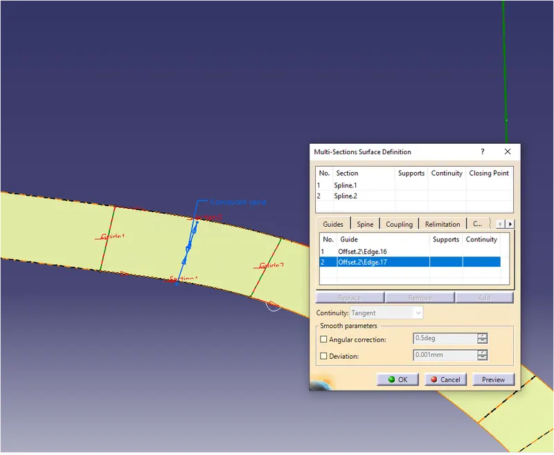
Then Using Multi-section Tool.
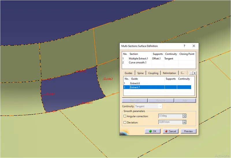
Mention Section-1& Section-2 Then Guid lines
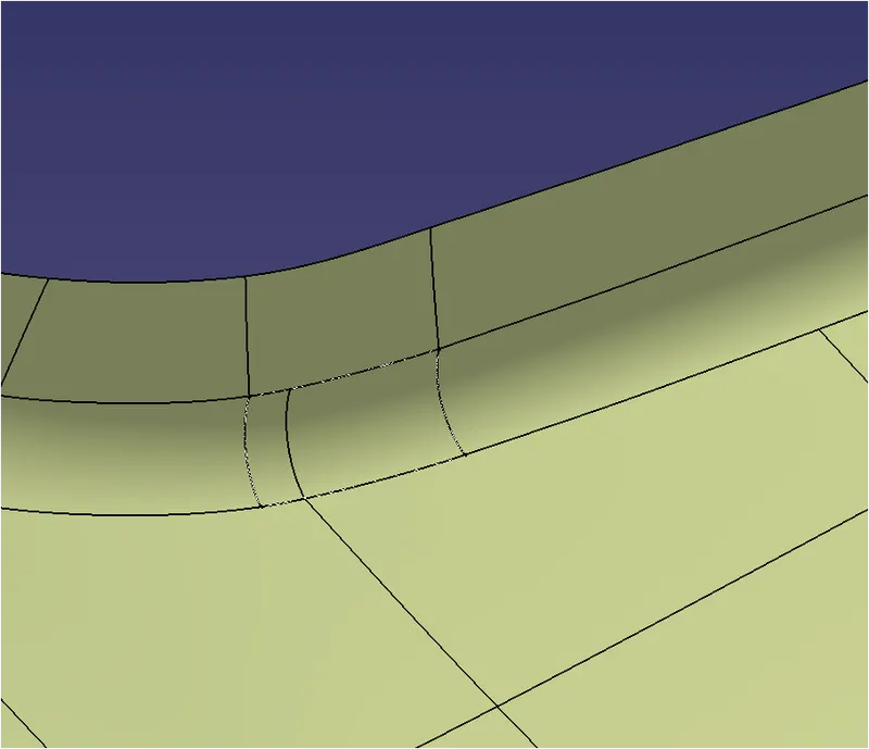
Noe Done That Missing Surface
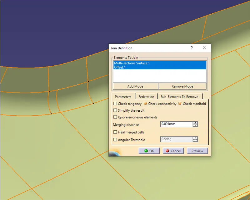
Now Joint The Surface & Off-Set Surface & Crate Surface
Now Crate C-Surface
* First Extract Surface boundary line
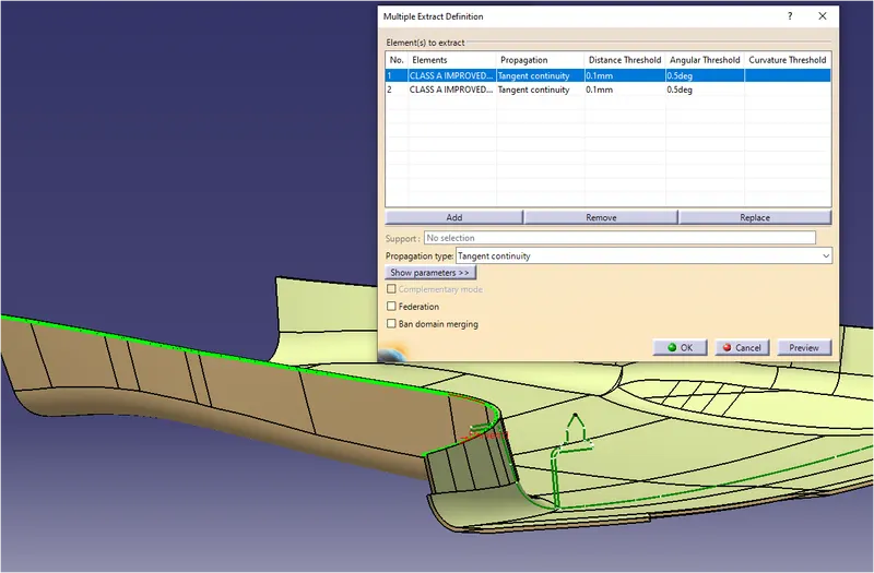
* Then Used Smooth Curve tool For That line
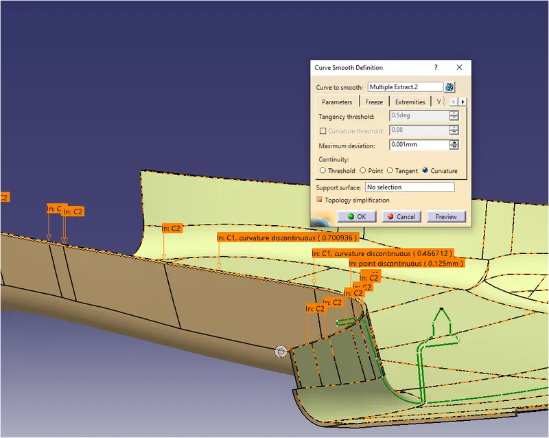
* In My Surface, I Have All ready Interesting line, In that interesting line in I care one Line
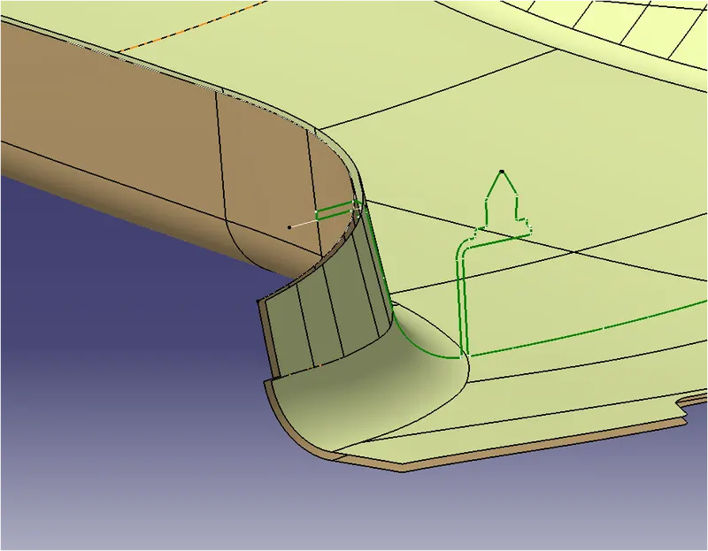
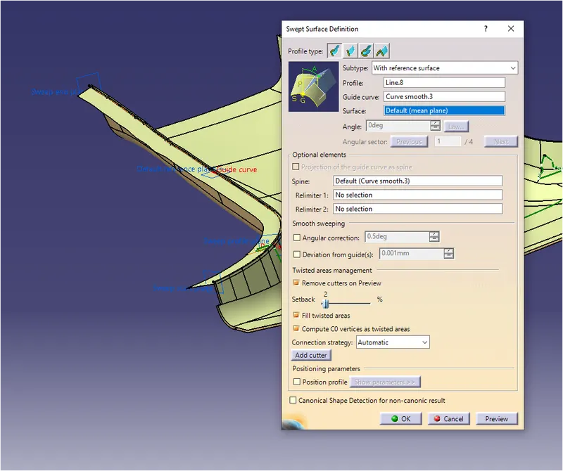
* Using the Sweep option I crated C-surface.
* The Same Operation Do it Opposite side fender Surface also.
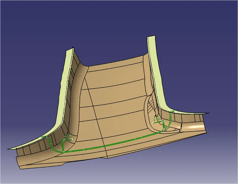
* Noe Trim With Surface
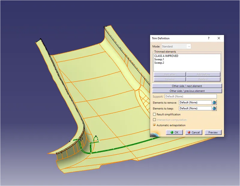
Now Crate B-Surface Flange Surface
* I Off-Set A-Flange Surface, Foo-Set Distance is 2mm
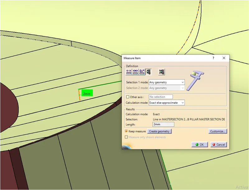
* Off-Set 2mm From A-Flange Surface.
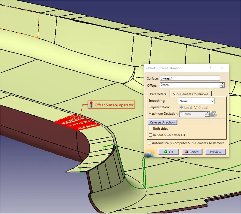
* I am Try to Off-Set the Surface But I can't Offset it Because this Surface too Curevater-Surface.
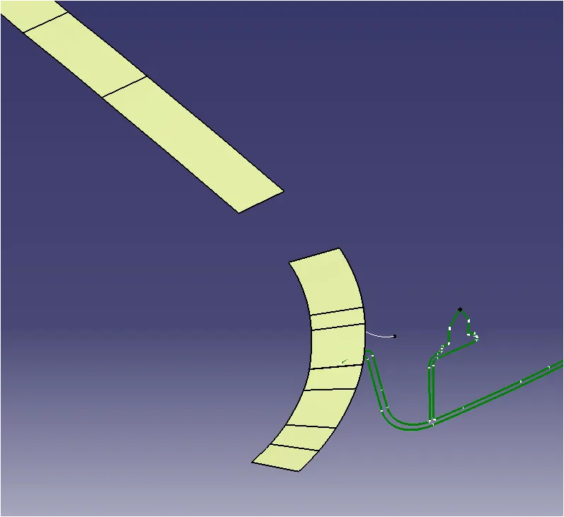
Some issues in surface, This Surface Create Manual.
1-I crate Guide Curve
2-Then Using Multi-Section tool
Crate Guide Curve By using Tool (Spline-Definition)
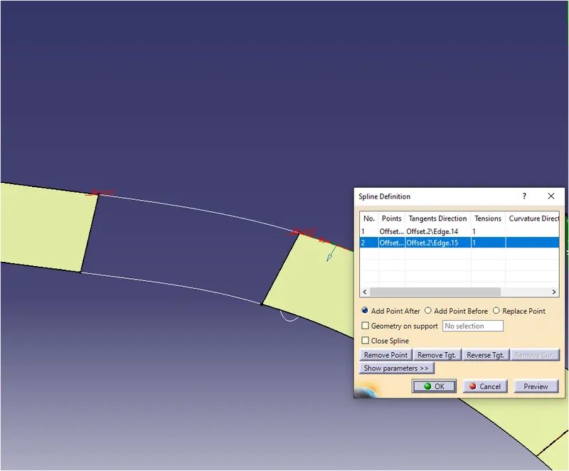
Now Using Multi-Section Tool.
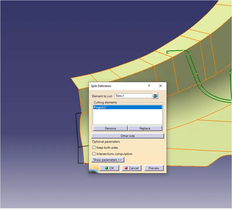
I have Un-uniform Surface So I Split That Surface.
1-Craye-Line
2-Project to surface Then Use Split Option
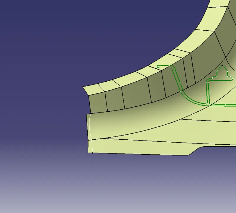
Project Line On Surface
Noe Split Surface By-Using Split Tool
Asine Fillet Corner Surface, Filet Given Take In Inter-setting Line
1-A-surface fillet 2.5
2-B-surface Fillet 4.5
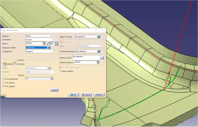
A-surface fillet 2.5
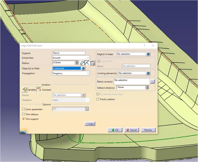
B-surface Fillet 4.5
Now C-Surface Trim With A-Surface.
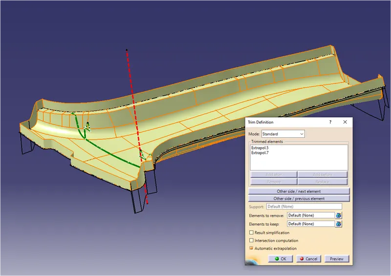
Now Trim With A & C Surface With B-Surface
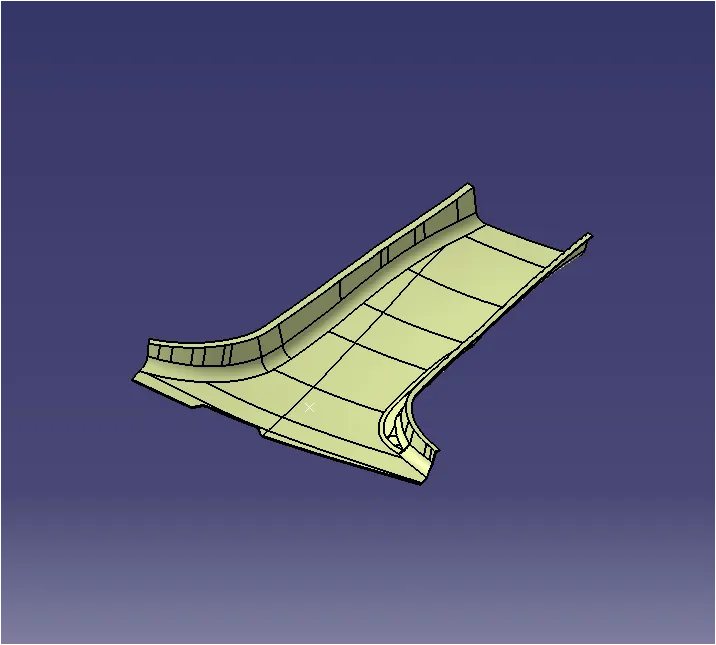
Checking Surface Fully Closed Are not.
* How to check means using boundary tool. If you get a Pop message in Surface Is Fully Close, Surface will be fully closed.
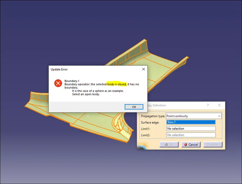
This is a Closed Surface
This Closed Surface Mance Surface will be converted to solid, by using the tool is Closed Surface Tool.
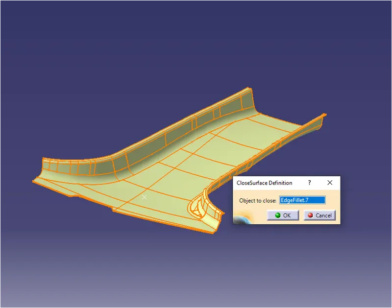
Bellow, I mention how is a solid surface
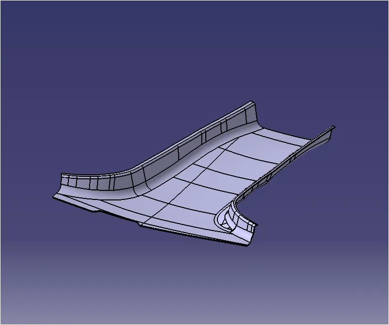
Now, we created Doghouse
If Create Doghouse an industry point of view there are many Rule conduction, is there below I mention clearly.
Draft - 0.5 degrees on walls of boss
Thickness - Typically 40%* of the nominal wall at the base.
Height to Diameter Ratio - 3:1
Radii - 0.25mm maximum radii.
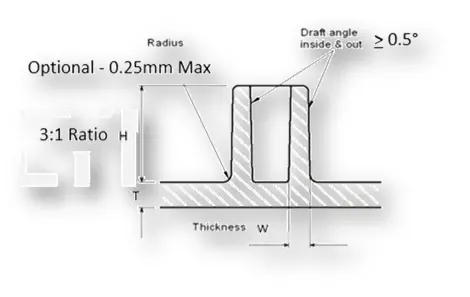
"C" is where the doghouse contacts the backside of the surface
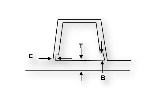
Doghouse wall thickness at the intersection of the part wall ( C ) should be 40% or less than the main wall stock ( T ).
Height of ( B ) should be between 3.0 – 6.0 mm
I Have Master Section from that master section to I take the line. using by point direction option
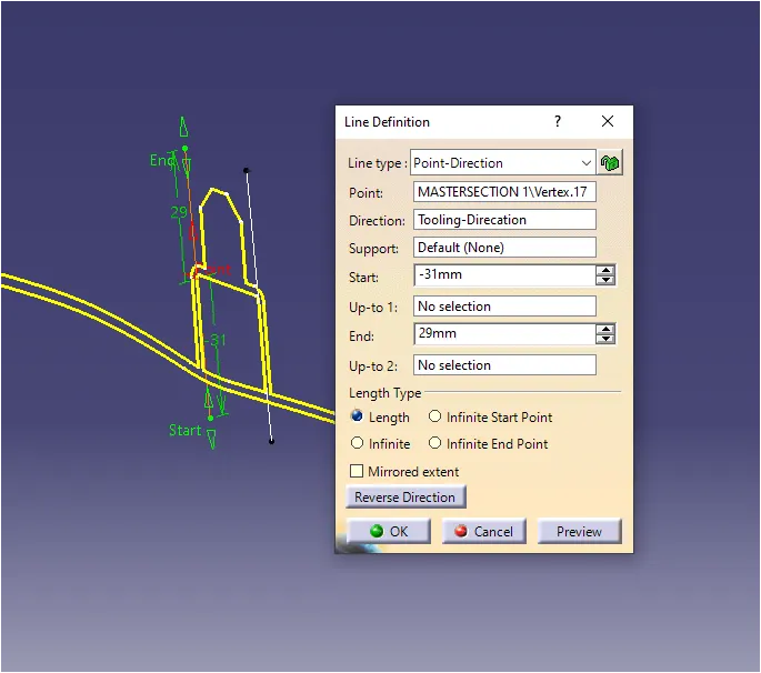
Then I Extrude That line.
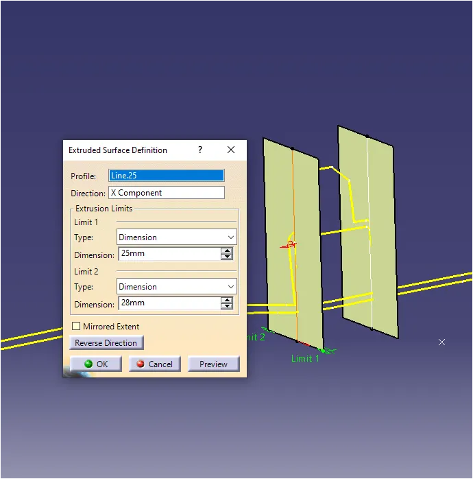
Since we already have the master section, with the master section as a reference here we will be creating the surfaces.
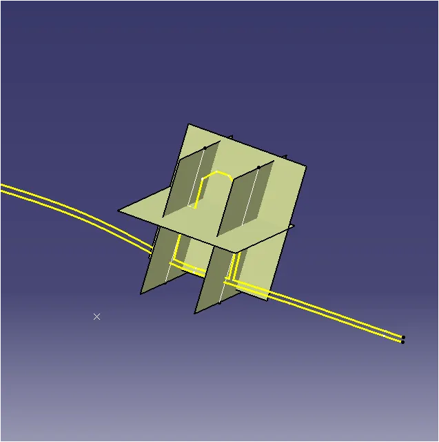
Then Trim unnecessary surface
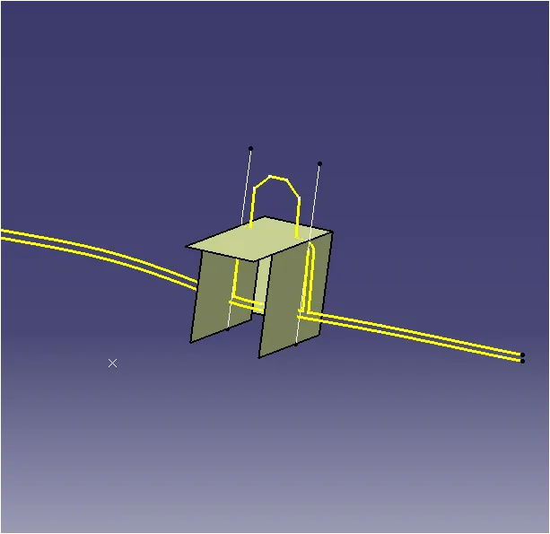
Now Split surface because we have unwanted feature surface.
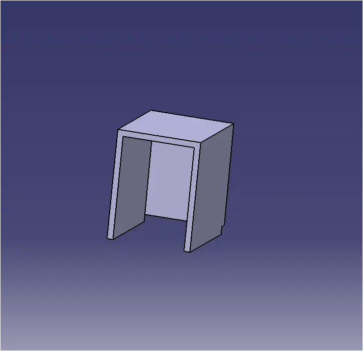
Crating Doghouse we have some basic rules, I mentioned before
So that basic points consider I will make doghouse.
B-pillar, Below Doghouse surface I off-set 4mm then > Doghouse side surface also offset 0.8. then TRIM these two surfaces.
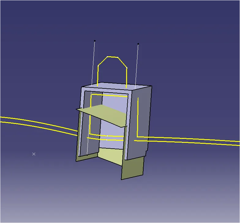
Split this with Surface
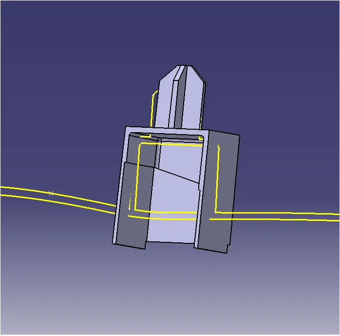
Now Assignee fillet properly
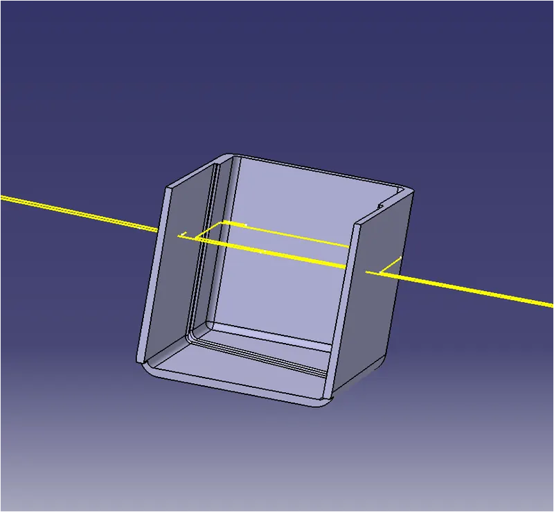
Now Crate 4-Way locater
* Make Sketch With iso-Construction
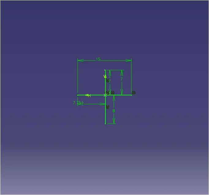
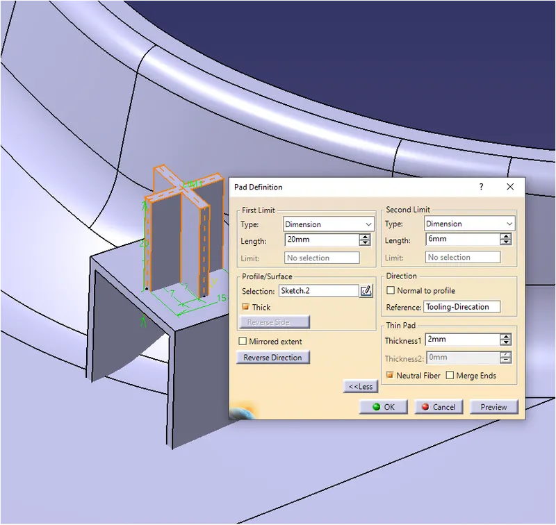
* Pad this sketch pad direction in the tooling direction.
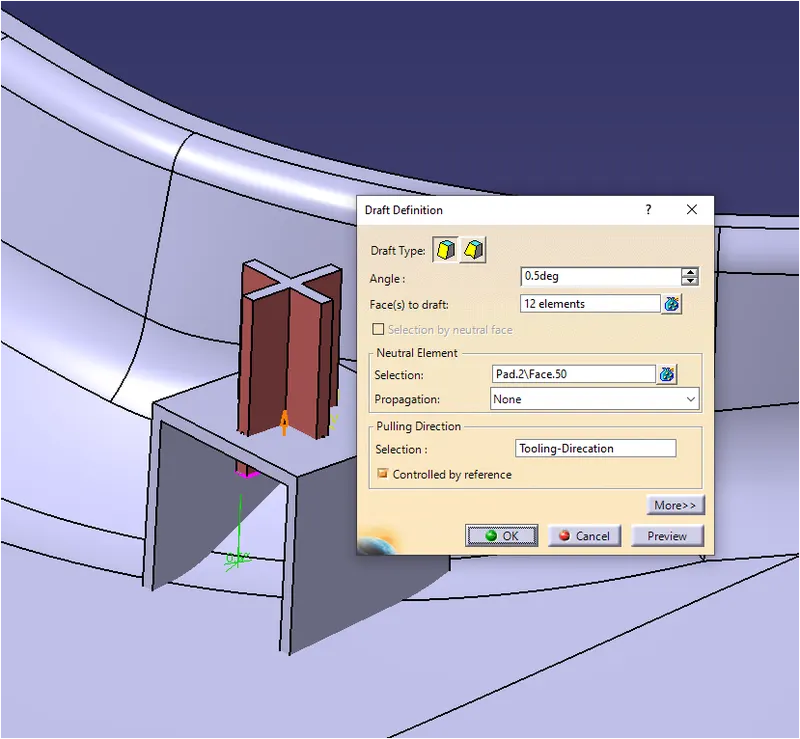
* Then Assigning draft dictation
* I do union trim hear
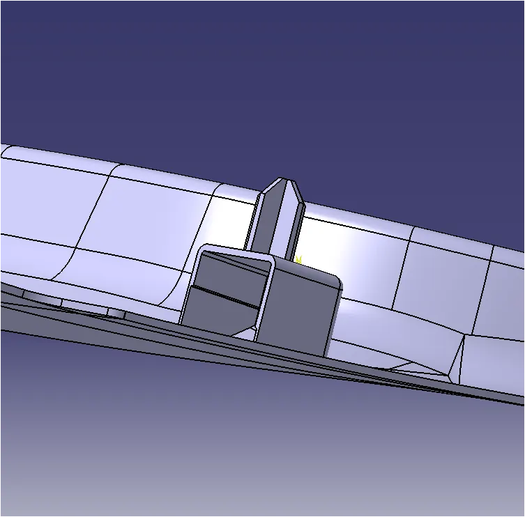
* Assigning Edge fillet
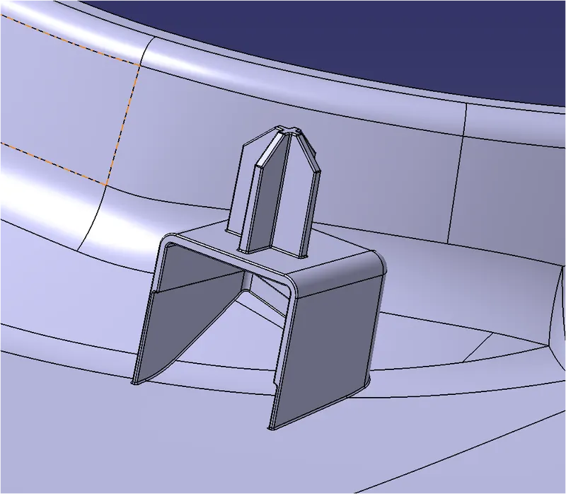
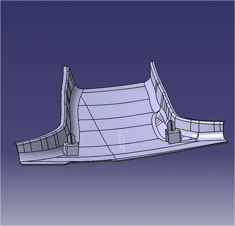
DogHoues & 4-Way Locater symmetry to another Side.
symmetry by using Pline
RIB CREATION
Crate Line but using point to the direction
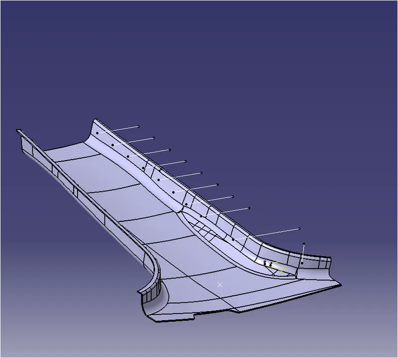
Extrude The Line along the required Deraction
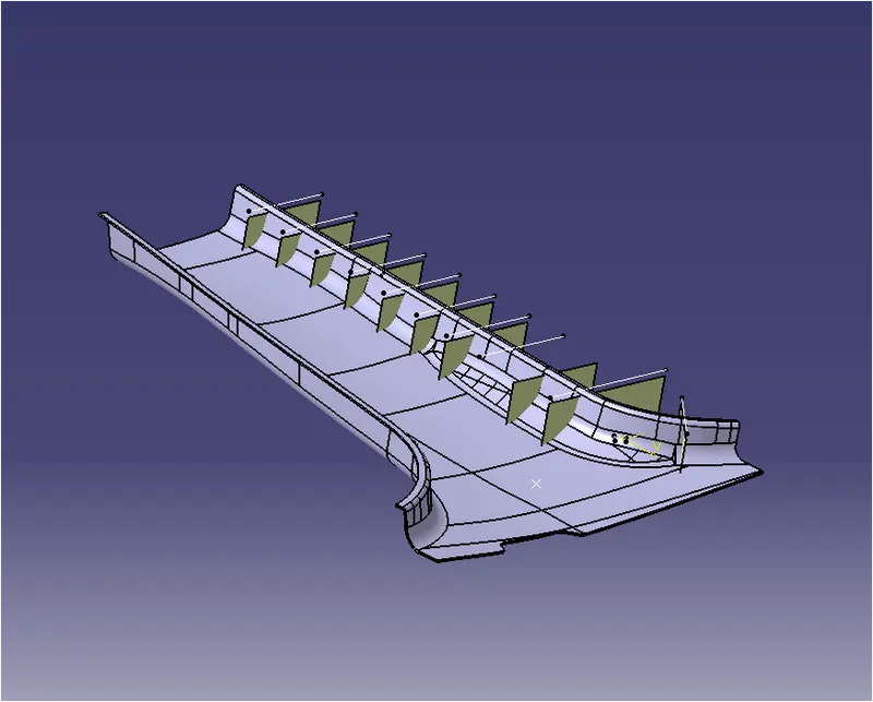
Then thicken the Extrude Surface.
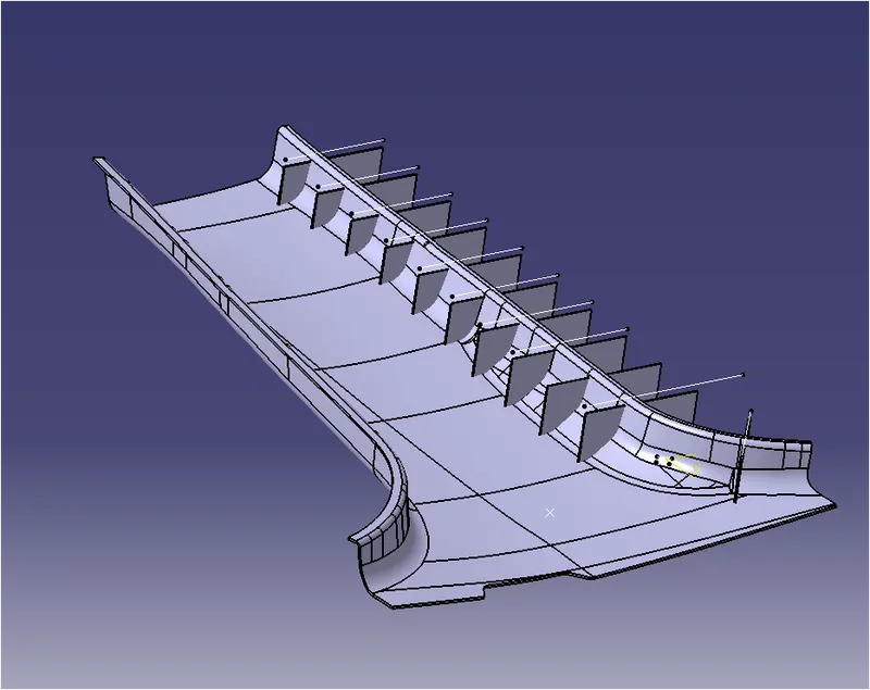
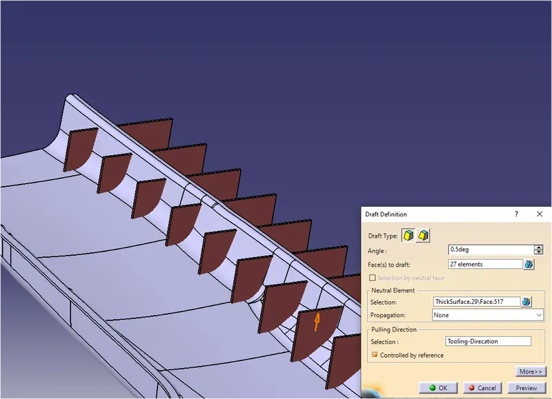
Then Assigning drafting direction
The neutral element is the bottom side of the RIB
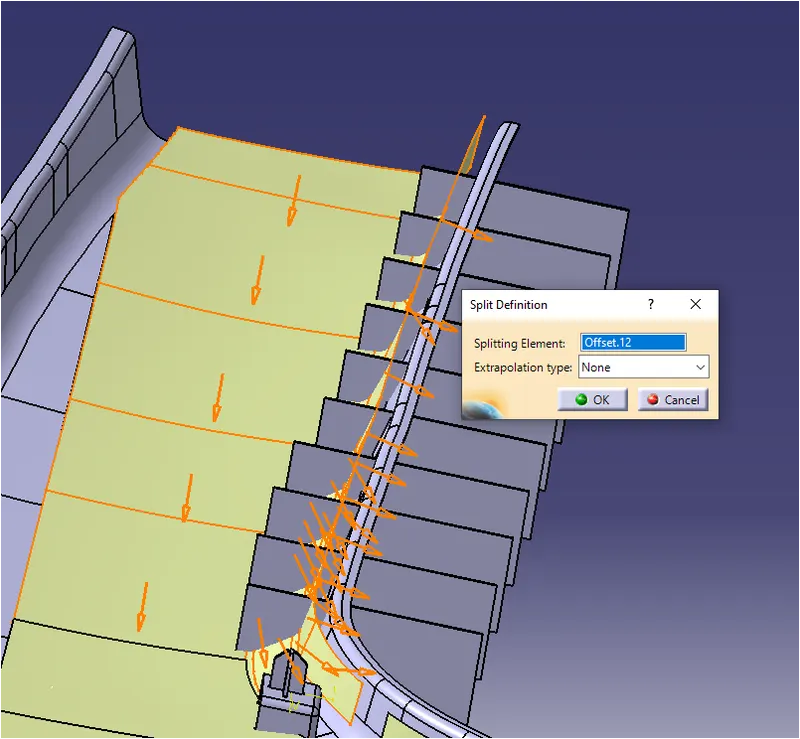
Off-set B-pillar mm, split with Rib surface
Assigning Fillet For RIB
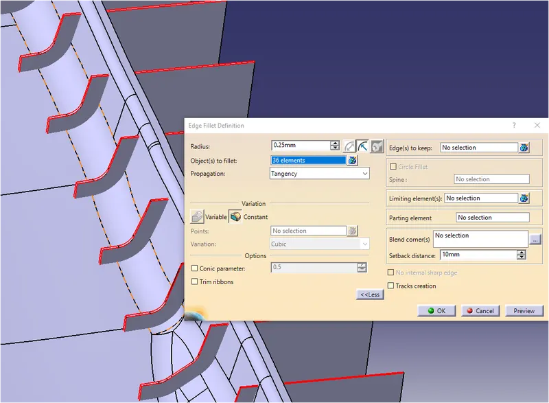
What we did in B-Pillar RH-Side for RIB, Everything will do it LH-Side Also.
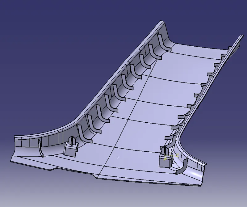
Now I Crated Intersecting For 4-Way locater & Doghouse
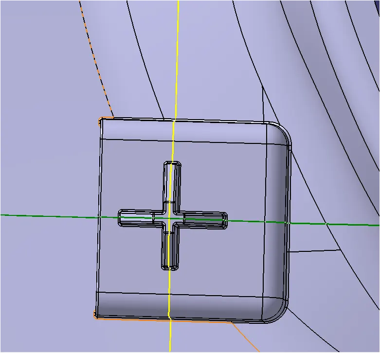
Draft Analysis
In This component, we want two tooling detraction
The first tooling detraction is B-Pillar & engineering feature also, but doghouse we crate extra one tooling. Explain below.
My A-surface And C-Surface Will be clear
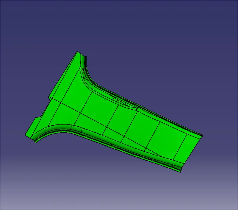
B-Surface Fully Covered
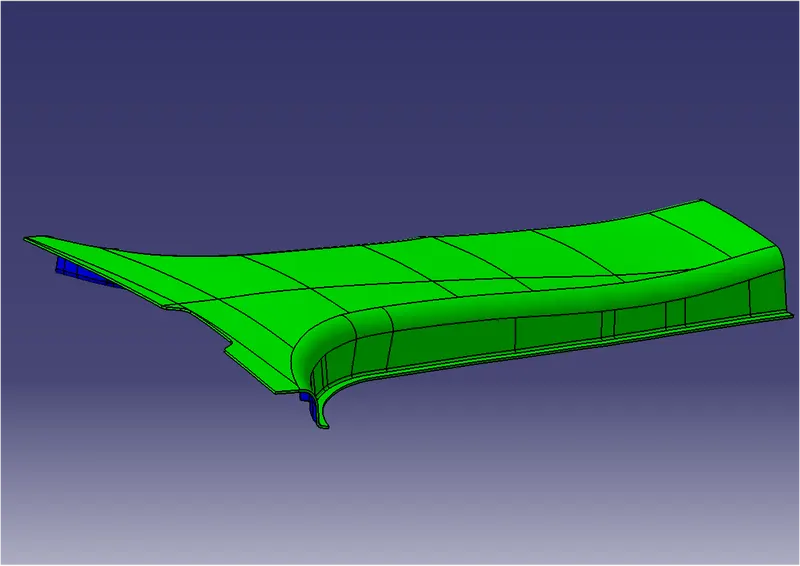
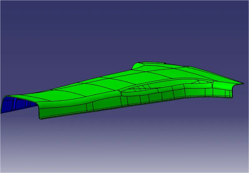
of Side, C-Surface covered Another portion will be cover in this Picture.
Rib B-Surface Tooling direction, Mostly A&C Surface will be green B-surface comes difference color, Below the picture I used inverse tool
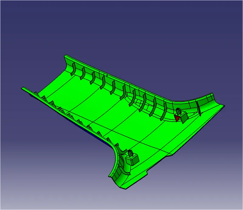
In this Picture Inside doghouse is failing for draft analysis so that portion only we crating tooling direction.
Doghouse inner portion Tooling detraction
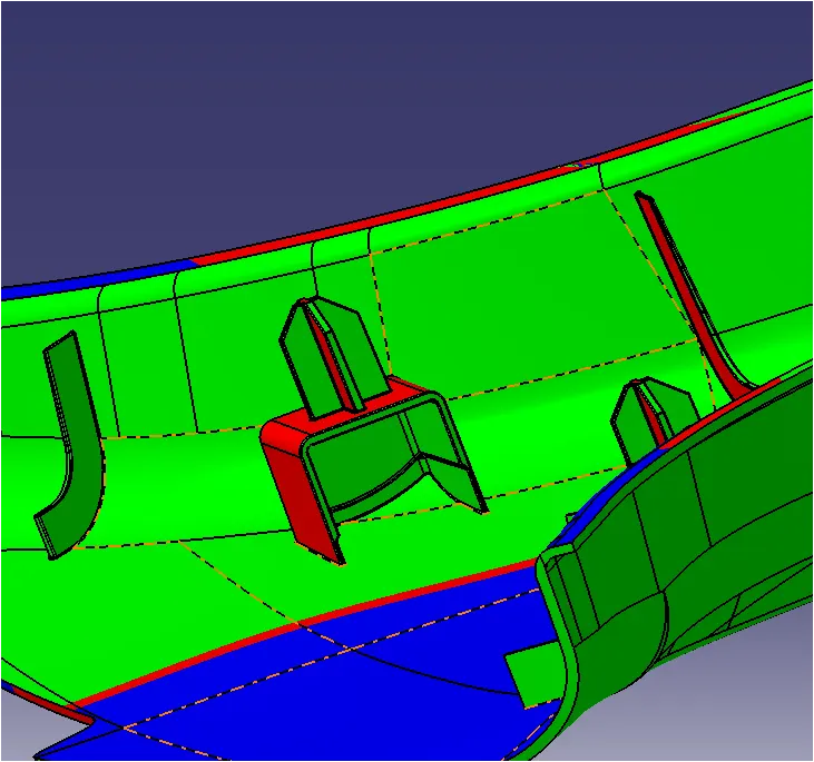
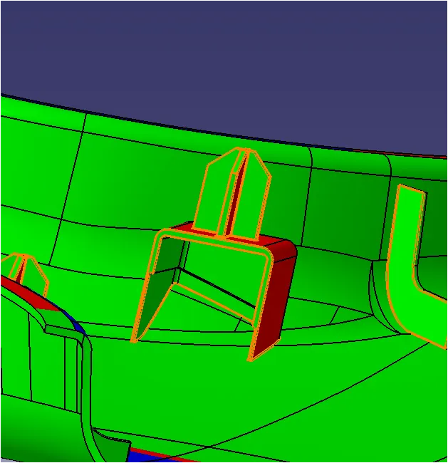
LH-Side Doghouse RH-Side Doghouse