Vehicle Door trim panel with Engineering Features
AIM:-
To create a solid body of Side Door plastic trim including the engineering features using CATIA V5 tool using the given Class-A surface and master section and adding thickness to the component.
Poly-Vinyl Chloride: This Type of plastic used in the vehicle door trim.
Development of a Door Trim panel.Creation of CAD model considering following inputs as like in OEM and tier1 companies
- a) Class A surface
- b) Nominal thickness: Refer to master sections
- c) Attachment strategy:
Door trim panel - a Door trim panel is an inner component of a side door of an automobile. it consists of garnish, map pocket, arm-rest, lower substrate. these are visible for the passenger and are finished with proper design aesthetics. the other side of the panel consists of fitments such as heat stakes, push-pins, and dog houses.
Plastic Parts:
- Map pocket - upper part
- Map pocket - the lower part
- Armrest split parts
- Lower substrate
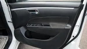
OVERVIEW OF DESIGN LIFE CYCLE IN AUTOMOTIVE INDUSTRY
Product Development process
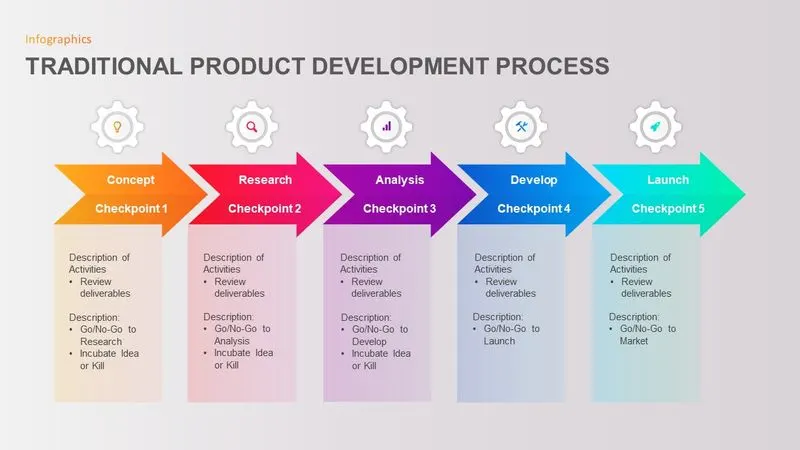
- Concept/ideation
This is the concept and ideation stage during which a product’s functional and performance requirements can be defined along with buyer personas or ‘the voice of the customer’. Customer requirements and innovative functionality design ideas are floated and explored freely to find compelling potential solutions that answer an identified market need.
- Feasibility study and design planning
The feasibility phase gives management an opportunity to evaluate a project’s potential success, reviewing and refining the business case from various angles. During this phase, the project team reviews product design concepts. They then select the design that best fulfills the previously defined user requirements. Now, the detailed, exhaustive project requirements are assembled that will guide the design and development phase.
- Design and development
In this phase, formal engineering specifications are created. Verification and validation plans are developed for the future. These are the final quality checks that will systematically determine that all agreed deliverables are present and working in the end product. The product is then developed against the designs, with regular checks made throughout the process to assess and mitigate the risk of its failure for the end-user and the project itself.
- Testing & verification
Comprehensive testing of the final product takes place to evaluate the robustness of the design and its ability to meet customer and performance requirements. Verification takes place against the design requirements identified in stage 2.
- Validation & collateral production
Validation takes place against the customer needs that have been identified at the ideation stage. Collateral is finalized and prepared to support the manufacture and launch phase.
- Manufacture/launch
Plans, specs, and other relevant documentation are transferred to manufacture for production, or software products and updates are released to customers. Marketing and launch plans are finalized and activated. Software products are released to customers electronically as updates or downloads.
- Improvement
The new product becomes part of the company’s portfolio. Ongoing product management ensures the product is subject to continuous upgrades and improvement. CAPA processes are in place to feed into these actions.
Designer rule
In class-a surface they give the master section, Bellow detailly explained about master section.
What is Master Section?
1 Master sections are the guides for design requirements that decide the component packaging after technical (Styling, Concept, or Class-A) surfaces.
2 Compound thickness & ware I want engineering feature like this all detail given in this master section.
PROCEDURE:
Interior Door trim consists of 4 Major components namely
1)Lower Substrate
2)Upper Substrate
3)Map Pocket
4)Door Arm Rest
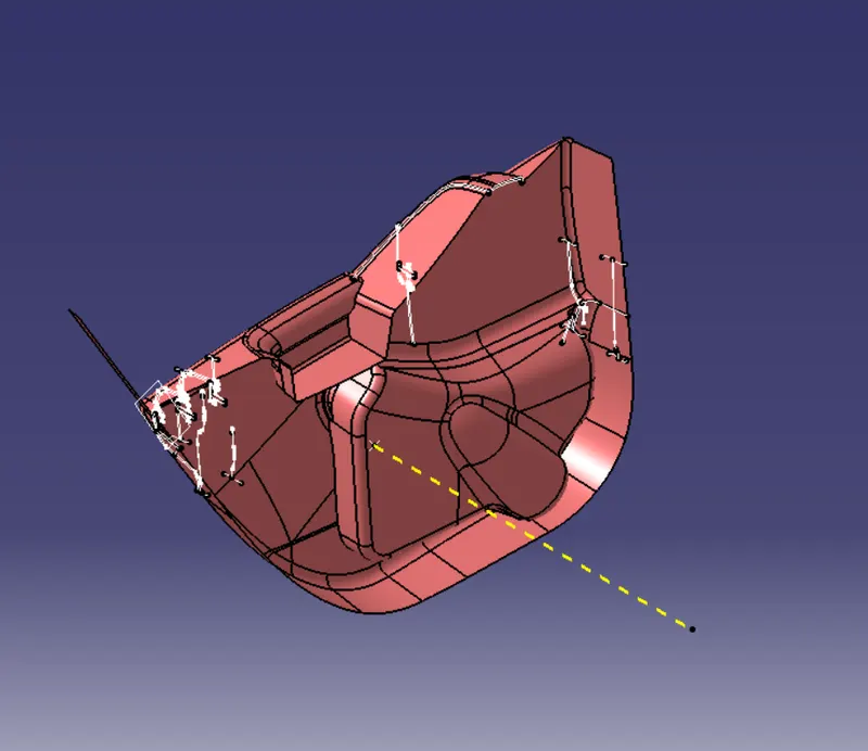
Input Surface
1)LOWER SUBSTRATE:
Given Class A Surface (Lower Substrate)
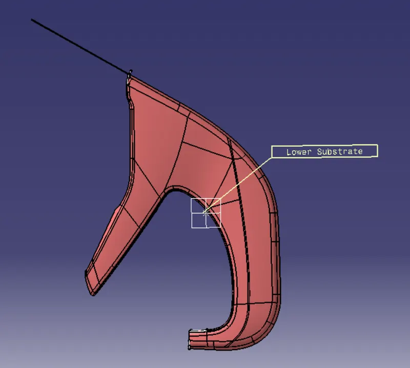
Tooling Axis Creation:
Why we creating a tooling axis because this axis angle the plastic part exited from the core.
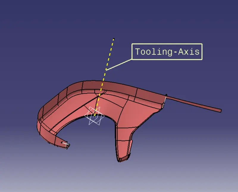
Draft Analysis of Class A Surface:
This lower substrate plastic part will be cleared tooling axis. possible manufacturing for this lower substrate part
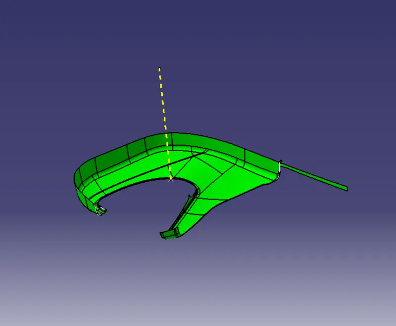
Clearing Class-A surface
In this case, some unwanted surface hears, Clearing that surface.
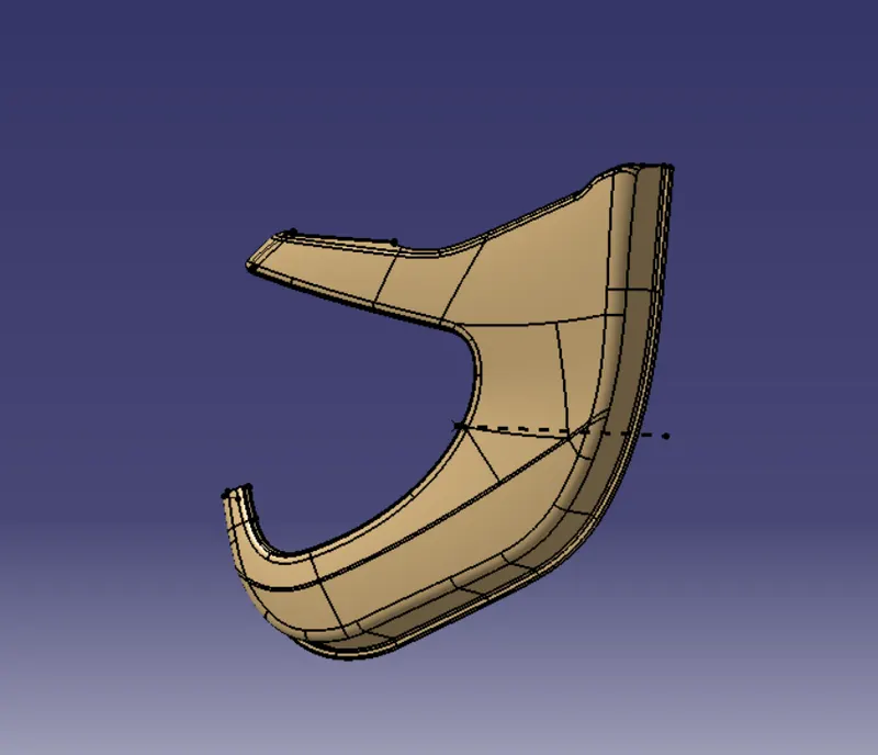
This's my edit surface
B-surface Creation
Select whole A-Surface Off-set 2mm this offset surface is B-surface.

Class-c Clearing
Extract Class-A surface Boundary & Extract Class-B Boundary Then This two surface between crate Class-C Surface.
Try to crate Class-c surface above 3deg. because this c-surface is considered for eject from the core side. C-surface crate above 3deg that surface ejects easily.
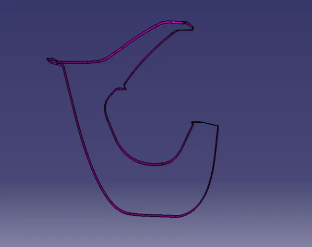
Closed Body
Change to Part Design. Select the Closed Body and then use the CLOSE SURFACE command to convert the closed Surface body to a Solid Body.
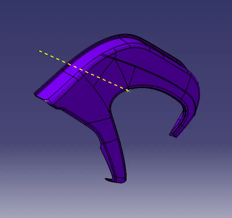
Draft Analysis.
Check the Draft analysis of the Closed Body with the tooling Axis
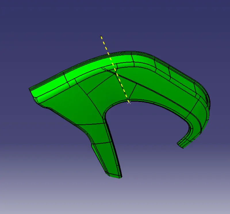
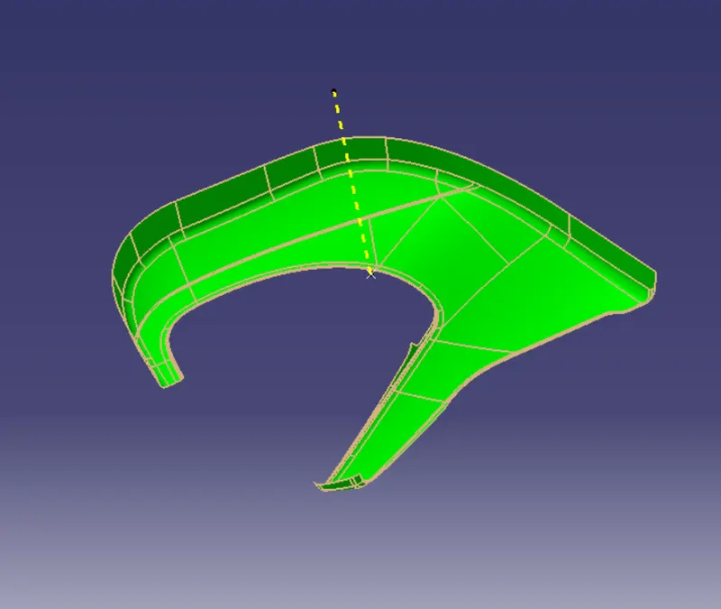
A-Surface Side B-Surface Side
2) UPPER SUBSTRATE:
Given Class A Surface (UPPER Substrate)
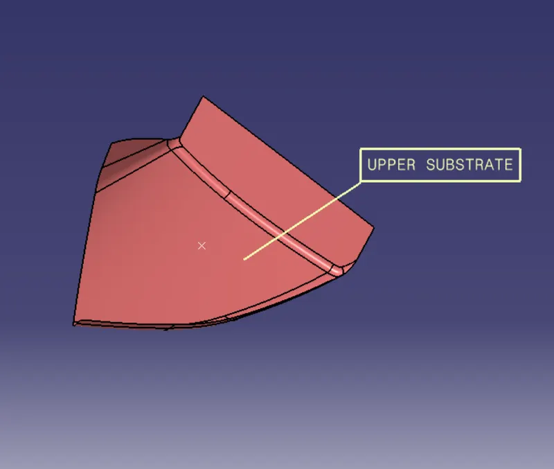
Tooling Deraction
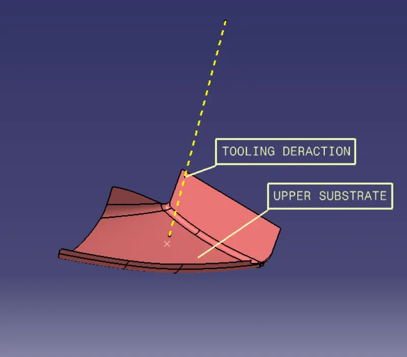
Draft Analysis of Class A Surface:
This lower substrate plastic part will be cleared tooling axis. possible manufacturing for this lower substrate part
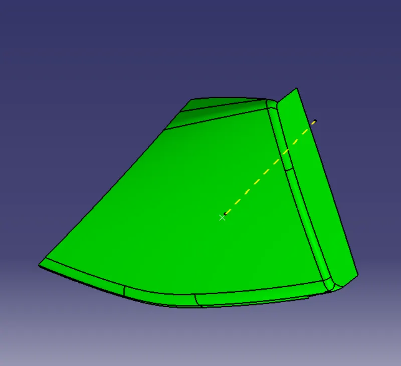
B-surface Creation
Select whole A-Surface Off-set 2mm this offset surface is B-surface.
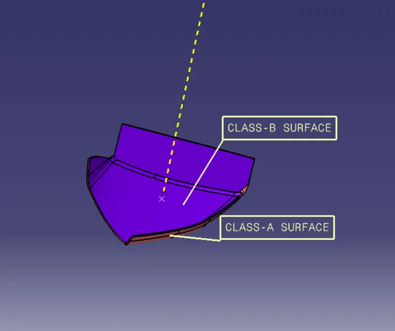
Class-c Clearing
Extract Class-A surface Boundary & Extract Class-B Boundary Then This two surface between crate Class-C Surface.
Try to crate Class-c surface above 3deg. because this c-surface is considered for eject from the core side. C-surface crate above 3deg that surface ejects easily.
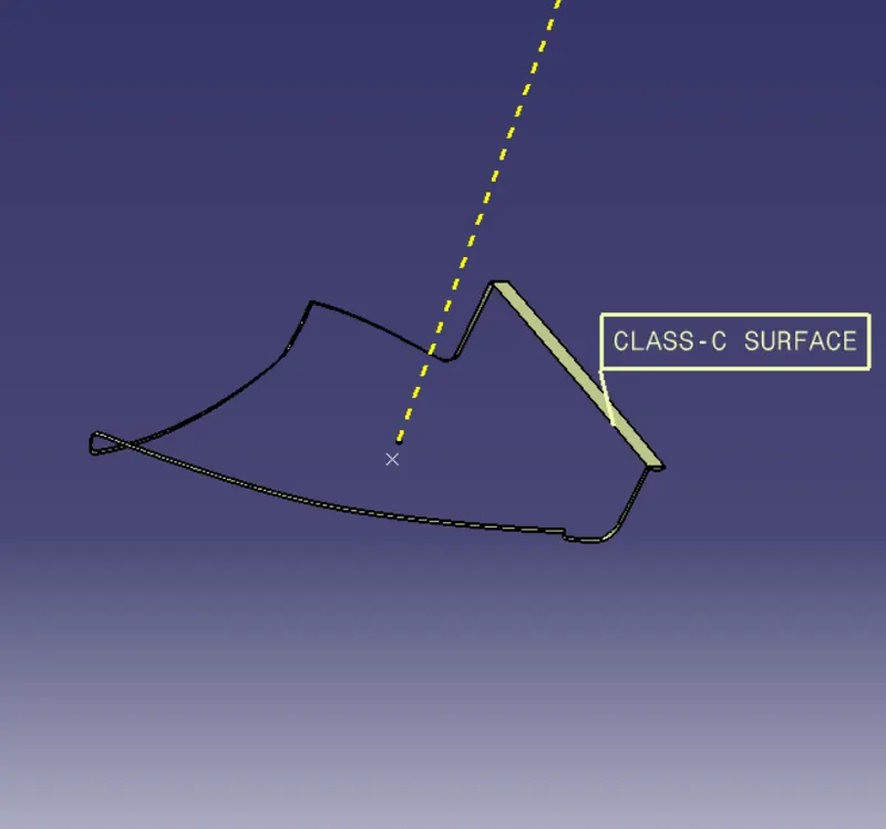
Closed Body
Change to Part Design. Select the Closed Body and then use the CLOSE SURFACE command to convert the closed Surface body.
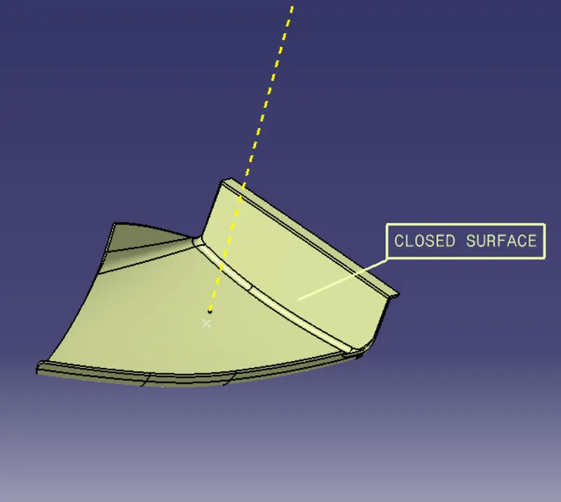
Draft Analysis.
Check the Draft analysis of the Closed Body with the tooling Axis.
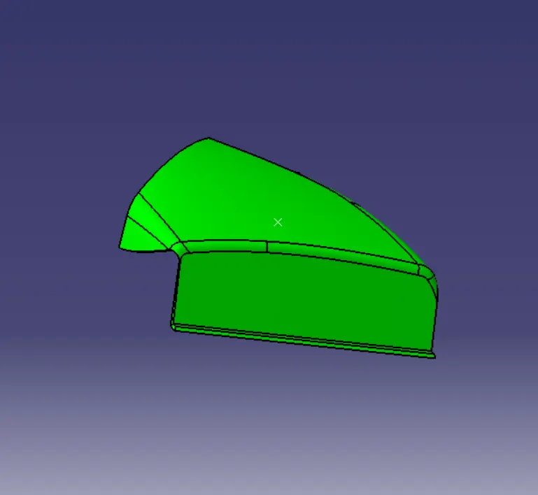
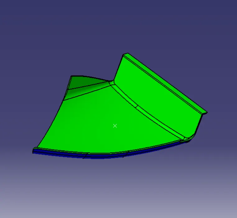
Class-A Surface Class-B Surface
3)Map Pocket
Given Class A Surface (Mappockt)
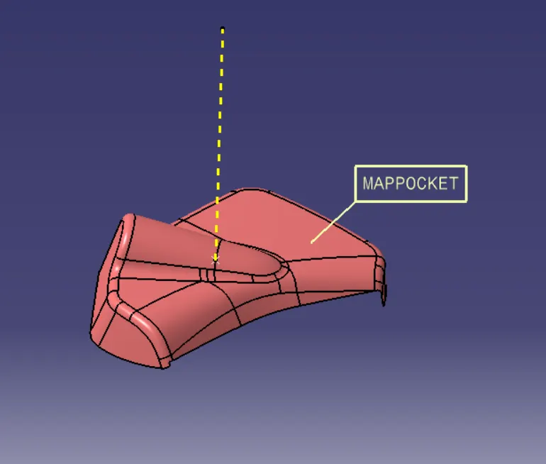
Tooling-Deraction
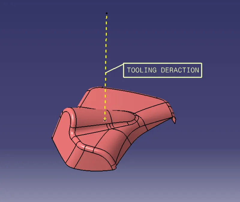
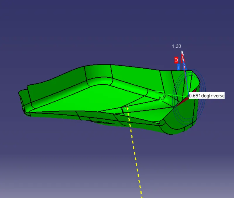
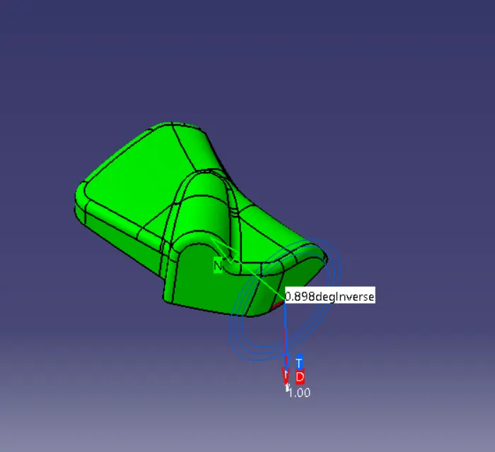
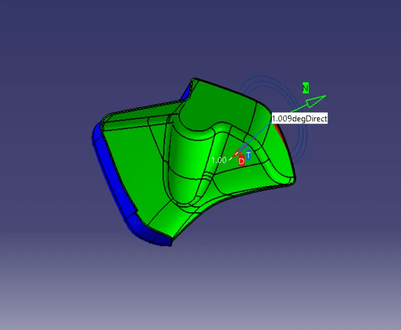
Draft analysis
Few surface-displayed red color. But that surface is not an issue because that surface is above 0.5 deg
The surface is we make below 0.5deg
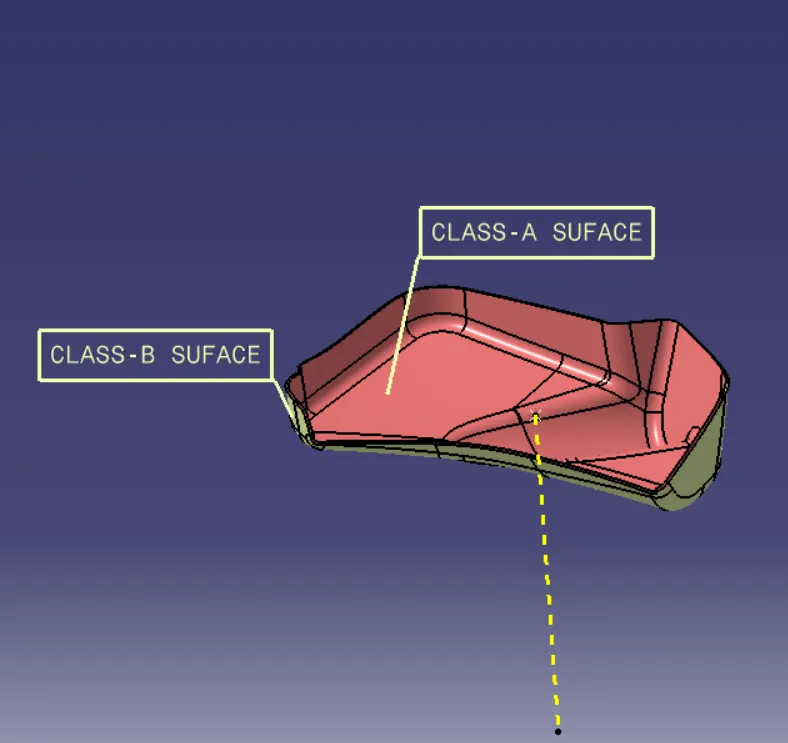
B-surface Creation
Select whole A-Surface Off-set 2mm this offset surface is B-surface
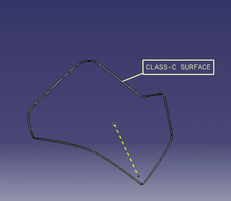
Class-c Clearing
Extract Class-A surface Boundary & Extract Class-B Boundary Then This two surface between crate Class-C Surface.
Try to crate Class-c surface above 3deg. because this c-surface is considered for eject from the core side. C-surface crate above 3deg that surface ejects easily.
Draft analysis.
Check the Draft analysis of the Closed Body with the tooling Axis.
4)Door Arm Rest
Given Class A Surface (DOOR ARM REST)
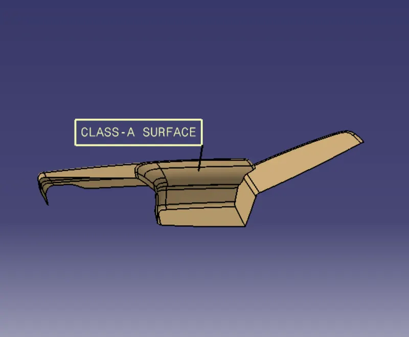
crate Tooling-Axis
Few surface-displayed red color. But that surface is not an issue because that surface is above 0.5 deg
The surface is we make below 0.5deg
In this case, I am used one tooling axis & one slider mechanism
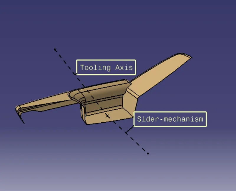
Checking Draft analysis for class-A surface
Slider mechanism Draft analysis. this axis angle middlebox compartment will be clear.
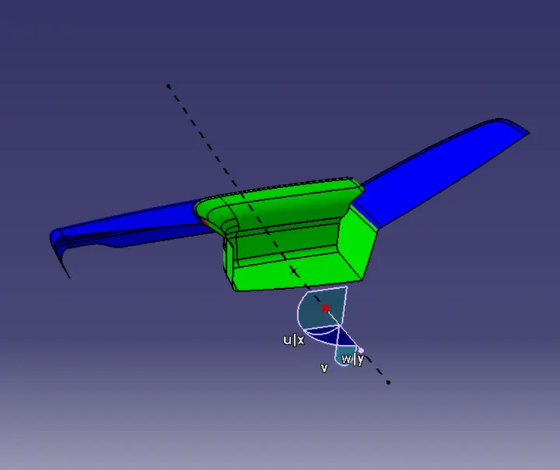
Tooling Deraction draft analysis. outer all surface will be clear.
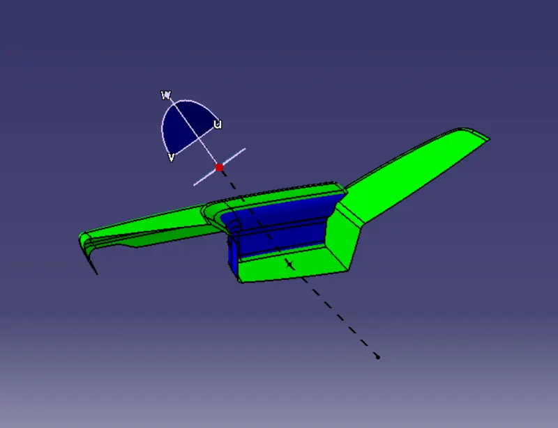
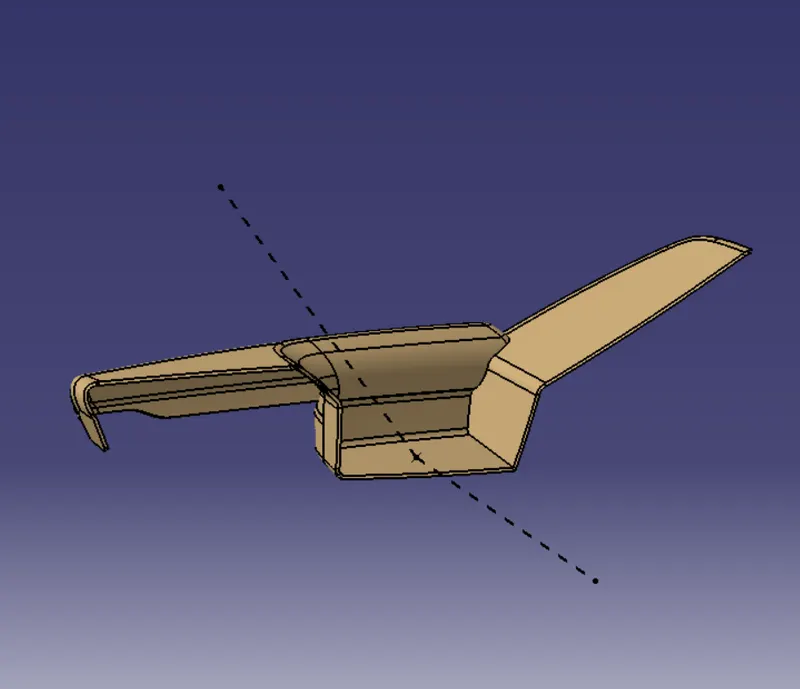
B-surface Creation
Select whole A-Surface Off-set 2mm this offset surface is B-surface.
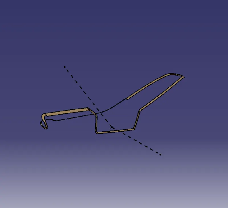
Class-c Clearing
Extract Class-A surface Boundary & Extract Class-B Boundary Then This two surface between crate Class-C Surface.
Try to crate Class-c surface above 3deg. because this c-surface is considered for eject from the core side. C-surface crate above 3deg that surface ejects easily.
Draft analysis.
Check the Draft analysis of the Closed Body with the tooling Axis.
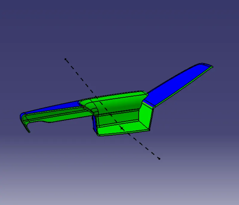
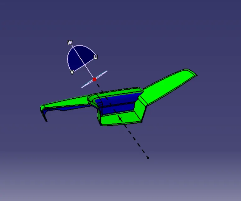
Slider Detraction draft analysis Tooling Deraction draft analysis
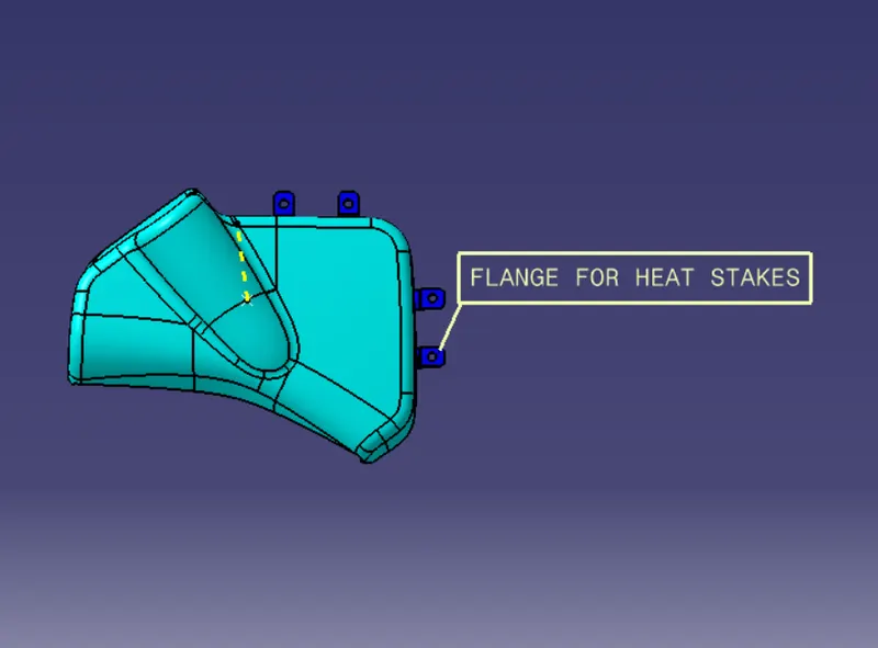
Creation of Flanges, Ribs, Dog house, and Heat Stakes :
Dog House :
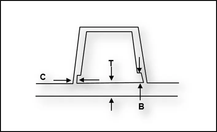
Create the dog house as per the design rules and give the required draft angle.
-
Doghouse wall thickness at the intersection of the part wall ( C ) should be 40% or less than the main wall stock ( T ).
-
Height of ( B ) should be between 3.0 – 6.0 mm
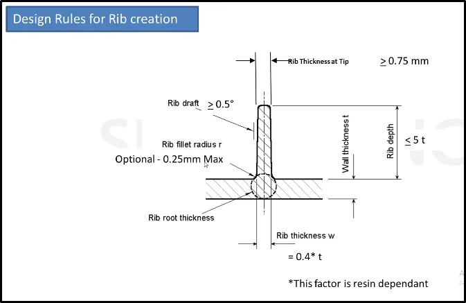
Ribs :
Create the ribs as per the design rules and give the required draft angle. Ribs are created to increase the stiffness and strength of the surface.
Heat Stakes:
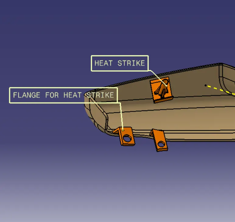
Heat Staking is a pulsed-heat process to join two or more parts out of which one at least is made of plastic. The process is to deform the plastic material using heat and force at a set process time. The bond is made by partially de-forming the plastic part in order to fix the other.
Map-pocket
Lower-Substrate Doghouse.
All Yellow color engineering is Doghouse
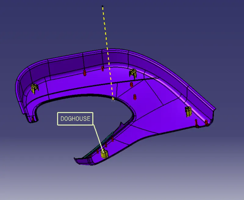
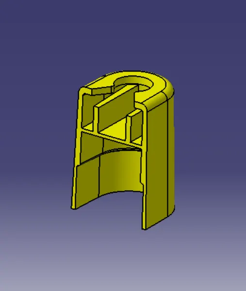
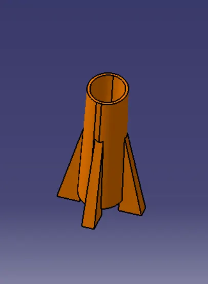
Doghouse Heat stakes
Lower-Substrate Heat stakes.
All Red color engineering feature is Heat strike.
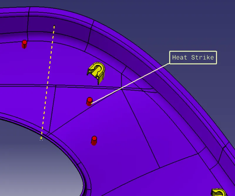
Heat stakes Tooling Detection
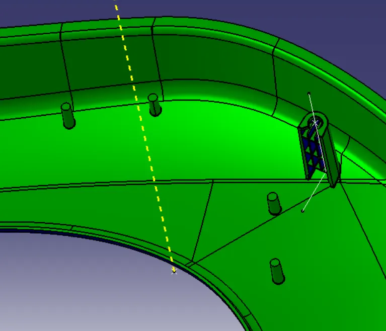
Lower-Substrate Flange For Heat stakes.
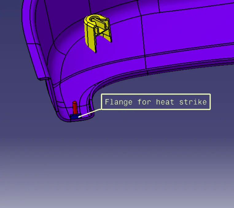
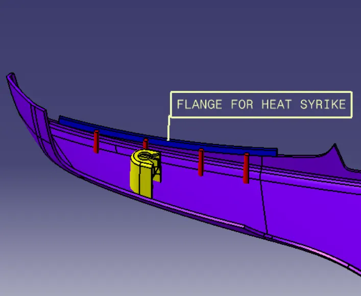
Doghouse Tooling-Deraction.
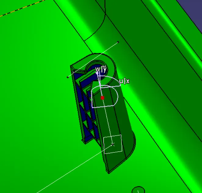
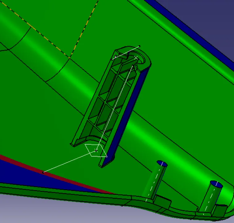
Tooling Deraction Sliding Tooling Deraction
Door Arm Rest
Final Assembly
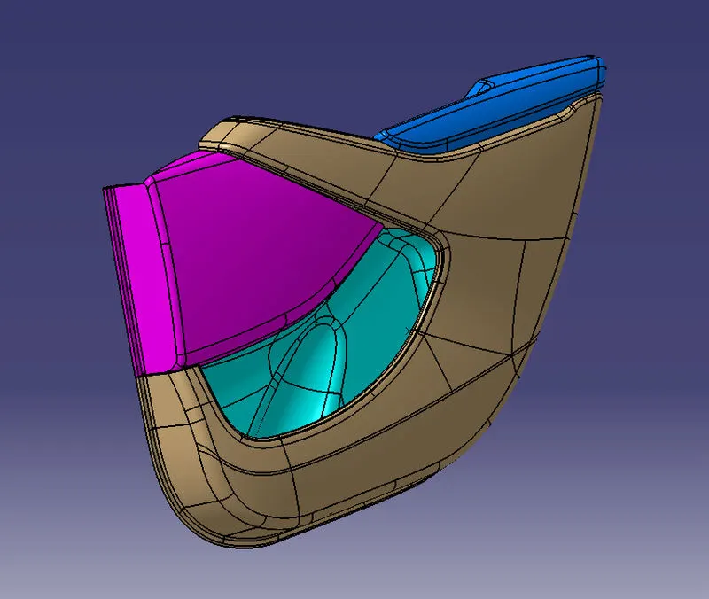
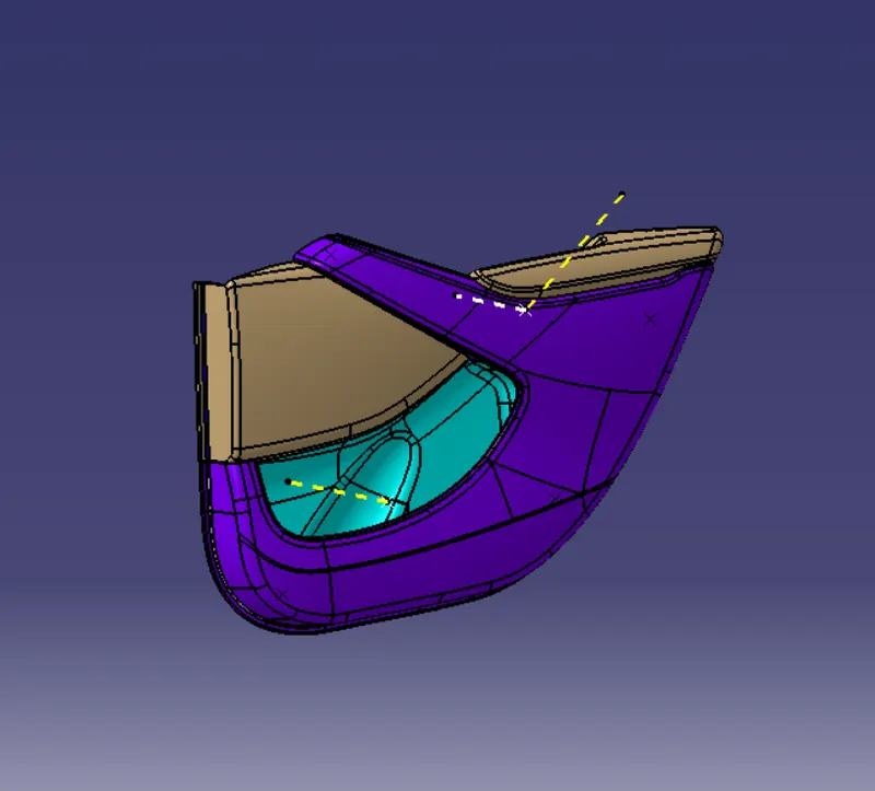
A-Side (Aesthetic Surface )
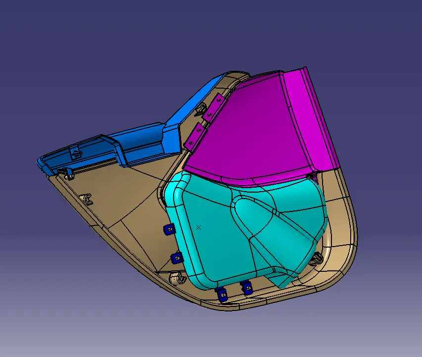
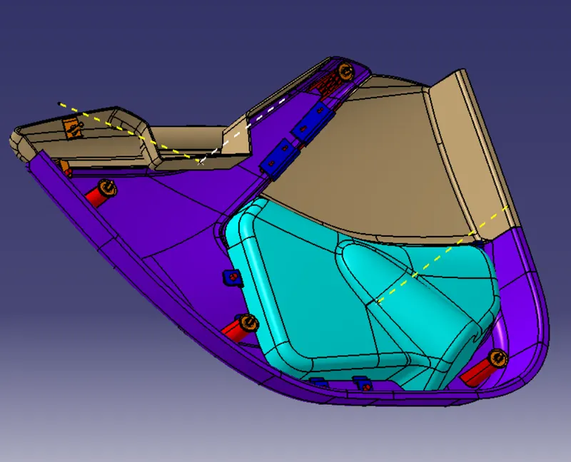
B-Side (Engineering Feature surface)
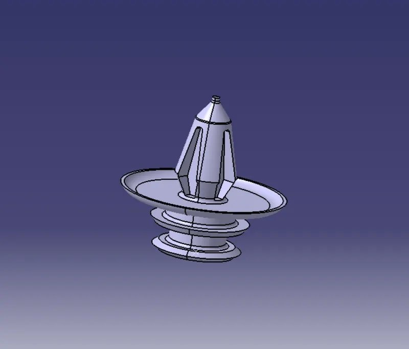
Push-pin
This Push pin assembles on the doghouse.
Final output Image.
RESULTS:
- Class A, B and C surface was created as per the automotive standards using CATIA V5 Software.
- Draft Analysis was performed for the built model and it could be seen the draft was under the permissible limit for the manufacturing of the component.
- B side features were created for the component as per the design Rules.