Meshing Vehicle Front Door Interior trim component (Project-1)
Introduction
- Vehicle Interior trim component. This is a plastic component EACH & EVERY PLASTIC COMPONENT MANUFACTURING MOLDING PROCESS,
- For every plastic part, we have three surfaces [A-surface, B-surface & C-Surface]
A-surface If you take one car what are surface do you visualize that all surface A-surface,
B-surface can't visualize surface it's all B- surface, engineering features make only B-SURFACE.
C-Surface Class-A & Class-B Surface between surface is C-Surface (or) Thicken surface is Class-C surface.
- The plastic component thickness is 2.5 to 3mm It's the standard thickness,
- This Compound fixed in the side door, This trim panel some places allocated for some parts [water bottle Career, door open & closed mechanism, speaker grid location].
- This interior trim making before consider engineering feature,
- This mostly used five engineering features
RIB,
SCREW BOSSES,
DOG HOUSE,
CLIP TOWER,
SNAP,
RIB
so why to hear rib will be used, because increase the plastic part strength, the rib starting thickness 0.8mm, so the rib thickness will be change depend upon the plastic component size,
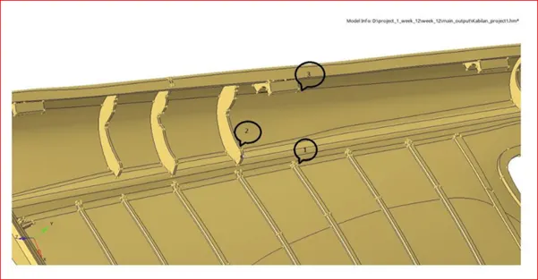
(Fig-1)
In this compound used three types of RIB First rib is given strength for the x-axis, the second rib is given strength for the y-axis, the third rib is for the snap, this snap tool is used flocking purpose
If you making a rib, consider in (DRAG ANGLE) This drag angle of 0.5-0.7 will be used this is also standard to all plastic components.
drag angle will reduce the RIB HIGHT is REDUCE, automatically plastic part strength also reduce
AIM ;
To perform Pre-processing of side door plastic component of a car. step involved in the process are
1 geometry cleanup
2 Extract midsurface for a given component
3 performed meshing on the extracted midsurface accounting to the given quality criteria
4 Assign thickness on each and every component
STEP_1 [ Import model ]
* Import that model in hyper mesh
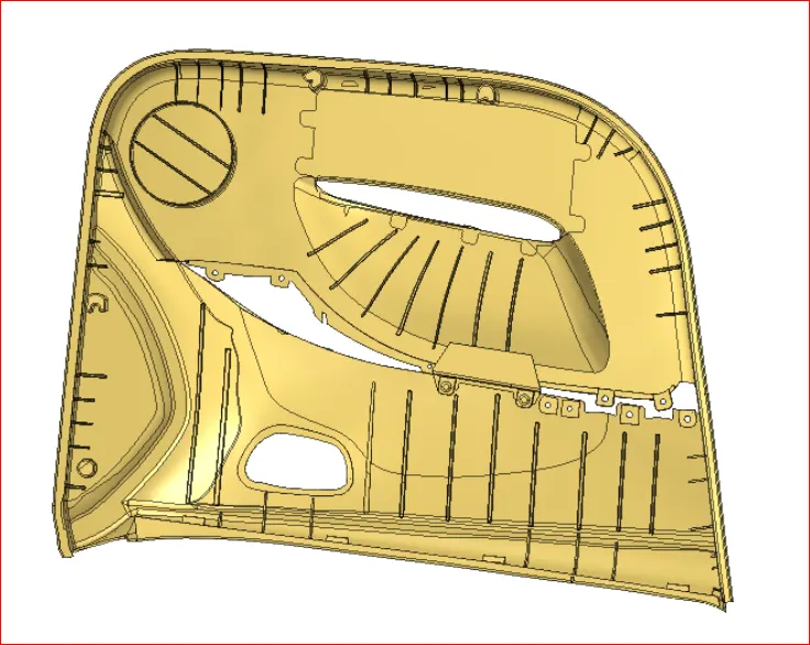
(Fig-2)
STEP_2
Tune on display fixed point, By using this option for visualizing a corner point
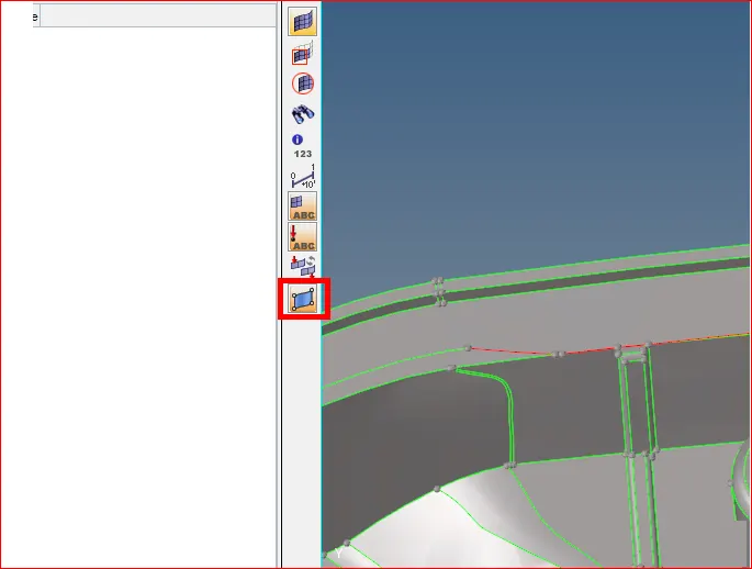
(Fig-3)
2.1_ By using tool topo mode, this tool is component surface clearly visualize
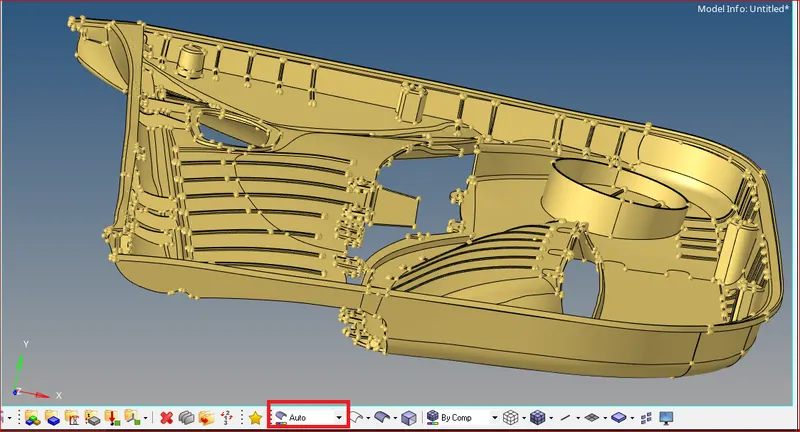
This Pick Using auto mode (Fig-4)
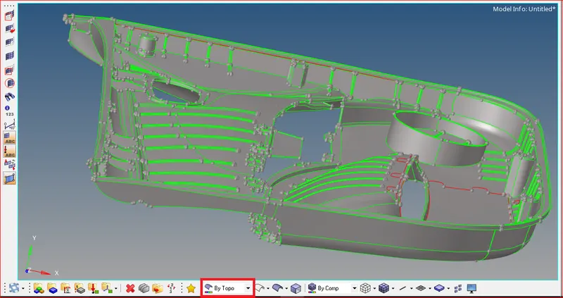
This Pick Using BY Topo mode (Fig-5)
STEP_3 Inspection
There is a plastic component
In this component by using more feature, everyone features a different dimension
Eg- [1 Rib Dimension 4mm, 2 Rib Dimension 2mm, 3 Rib Dimension 27mm]
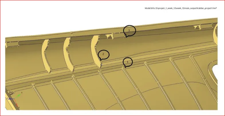
(Fig-6)
3.1_Free edge in the parent component
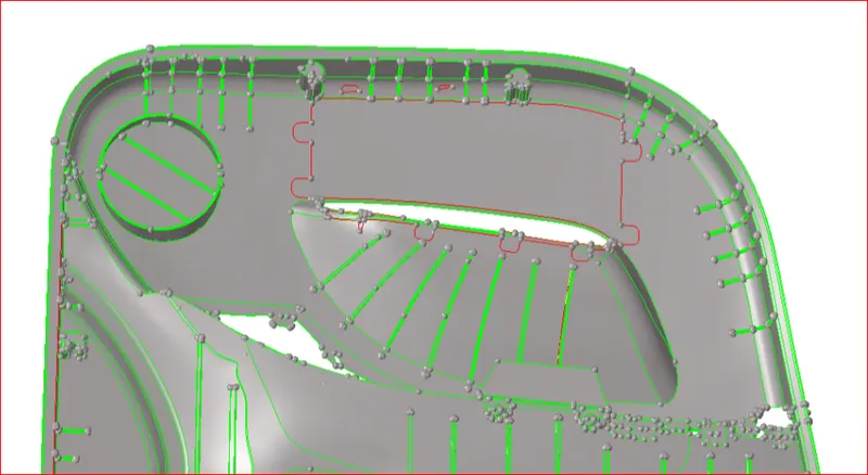
(Fig-7)
3.2_OPPEN SURFACE in a parent component
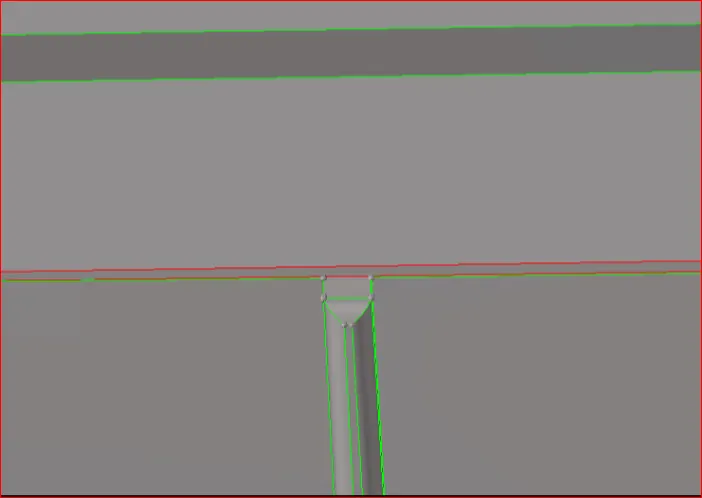
(Fig-8)
3.2.1_OPPEN SURFACE in a parent component
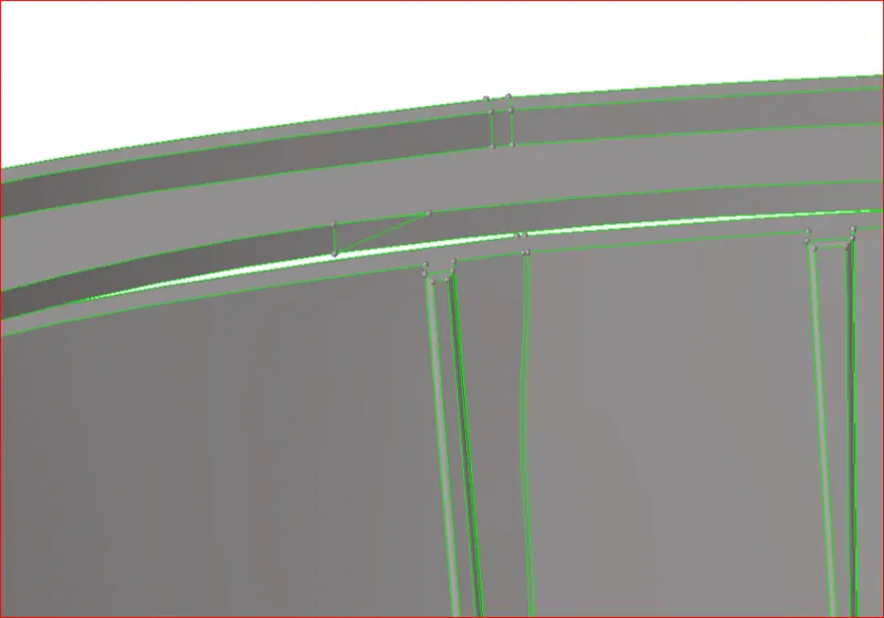
(Fig-9)
3.3_ MORE NUMBER OF RIB used this component
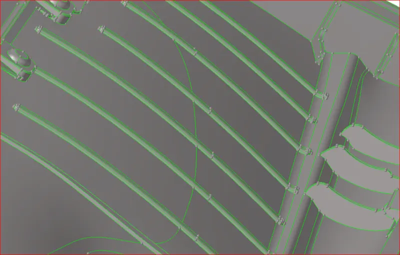
(Fig-10)
STEP_4 GEOMETRY CLEANUP
4.1_ In Parent Component some Surface will be open, that type of surface solves to manual
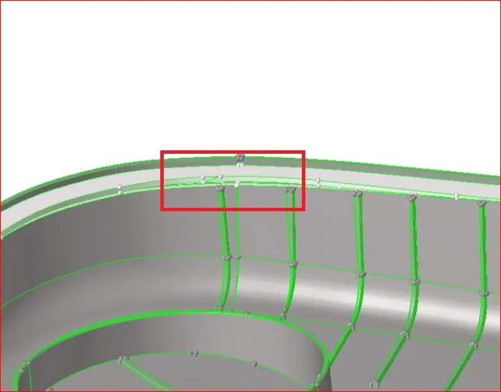
(Fig-11)
This open surface point replaces the near-surface point (or) delete surface & recreate surface. its open surface solved
By Using Tool DELETE (F2) > CHANGE ELEMS TO SURFACE > SELECT SURFACE > DELETE

(Fig-12)
4.2_ Select surfaces
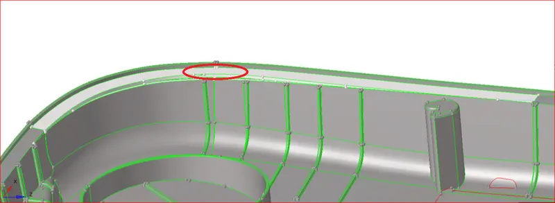
(Fig-13)
4.3_ Delete Surface
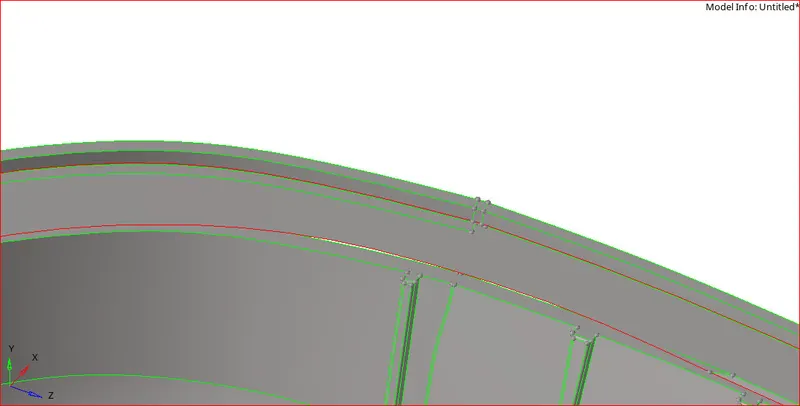
(Fig-14)
4.4_ Crate surface
By Using Tool GEOM > SURFACE > RULED
How to make surface refer [Fig(15_16_17)]

(Fig-15)


(Fig-16)
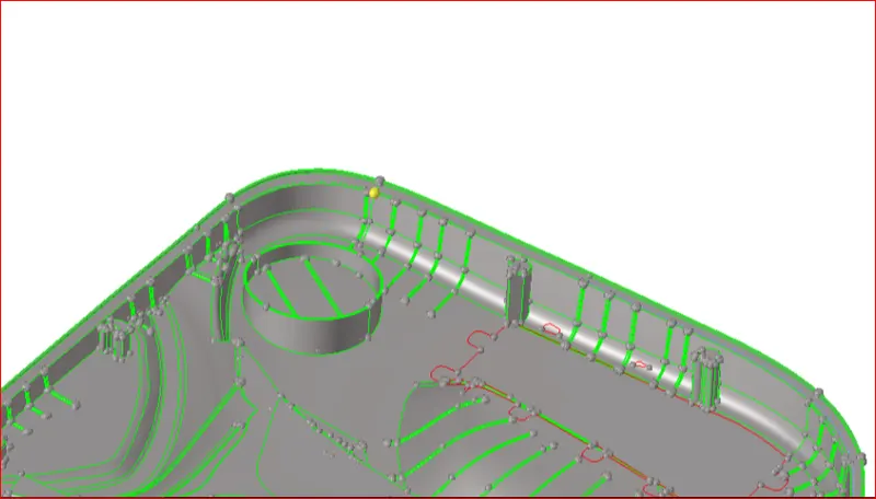
(Fig-17)
4.5_ Done creating a surface
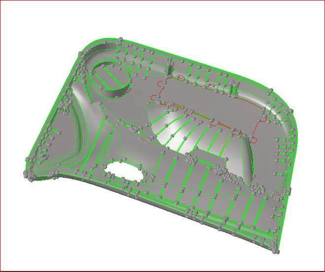
(Fig-18)
STEEP_5
5.1_ Find out the minimum length for given quality criteria because this minimum length failing for element,
By Using Tool DISTANCE (F4) > Select two-point options > find out the distance

(Fig-19)
5.2_ That surface point replace to near-point
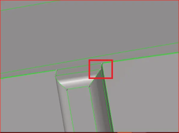
(Fig-20)
5.3_ suppose Shude be near no point available, that time we crate point to the near line then replace to that point
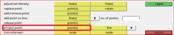
By Using Option Quick Edit (F11) > PROJECT POINT
(Fig-21)
select a point then select the required line, now point make on the line.
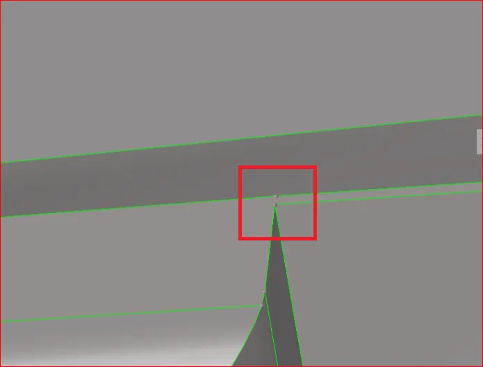
(Fig-22)
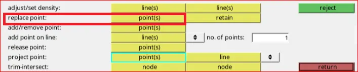
5.4_Replace project point By Using the replace tool
Quick Edit (F11) > replace point
(Fig-23)
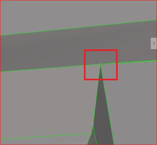
5.5_Noe Done replace point, now minimum length quality criteria failing is avoid in this surface
(Fig-24)
STEP_6
6.1 Parent component surfaces some surface interesting to other surfaces
* This type of issue solve in a manual, like delete surface & recreate the surface
(Fig-25)
6.2_ First inspection that surface, By Using mask option
By Using Tool MASK TOOL > SELECT SURFACE > MASK

(Fig-26)
6.3_ What are the surface not needed a mask to all surface
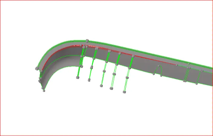
(Fig-27)
6.4_ Now delete interesting surface
By Using Tool DELETE (F2) > CHANGE ELEMS TO SURFACE > SELECT SURFACE > DELETE
(Fig-28)
6.4.1 Select surfaces
(Fig-29)
6.4.2_ Delete Surface
(Fig-30)
6.4.3_ Crate surface
By Using Tool GEOM > SURFACE > RULED
(Fig-31)
(Fig-32)
(Fig-33)
6.4.5_ Done creating a surface
(Fig-34)
6.5_ Defeature ribs
Defeature Parent component Ribs because rib fillet is failed for meshing
under image go to de feature (ref-Fig-35)
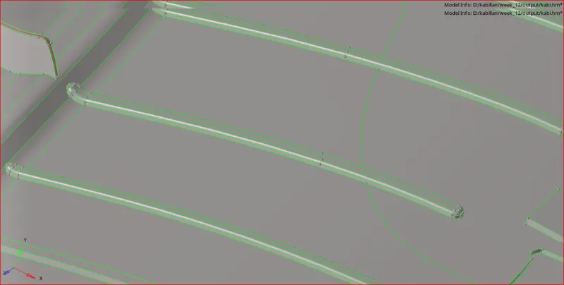
(Fig-35)
Defeature rib By Using Tool Geom > DEFEATURE >

(Fig-36)

(Fig-37)
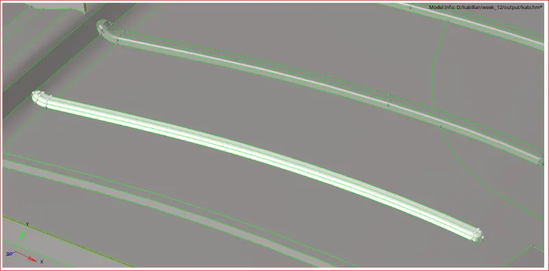
(Fig-39)

(Fig-40)
Done defeature ribs, but still rib corner Fillet no defeature properly [Ref (fig -41)]
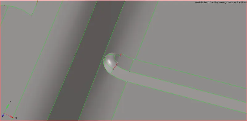
(Fig-41)
This corner fillet defeature remove solve different method [Ref (fig -41)]
By Using Tool
i DELETE (F2) > SURFACE > DRAG > LINE SELECT LINE > SELECT VICTOR > PUT DISTANCE > +DRAG
(Fig-42)
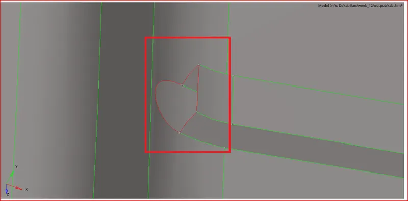
(Fig-43)

(Fig-44)
Now drag the line required distance [Ref fig_45]
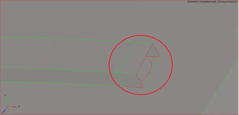
(Fig-45)
Now Full the open surface [Ref fig_45]
By Using Tool GEOM > SURFACE > RULED
(Fig-46)
(Fig-47)
Crate surface For open surface [Ref fig_49]
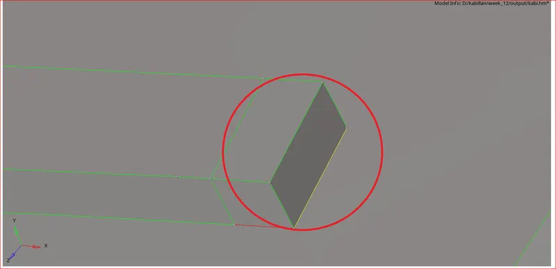
(Fig-49)
STEP_7
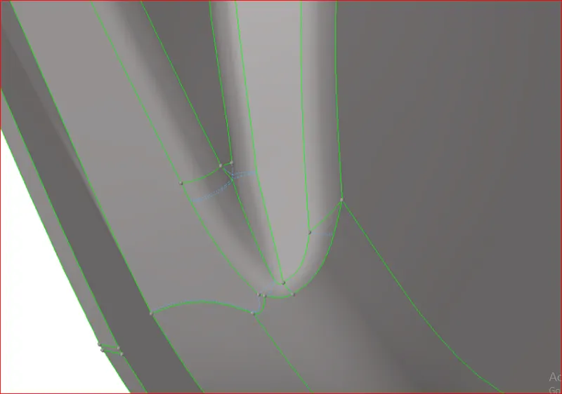
7.1_ Toggle unnecessary line in the parent component
By Using Toggle tool in (F11) QUICK EDIT > TOGGLE
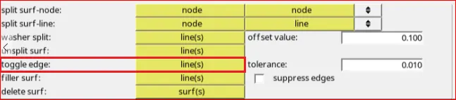
(Fig-50)
7.2_ Find out the minimum length for given quality criteria because this minimum length failing for element, so toggle the minimum length line
(Fig-51)
STEP_8 CRATE midsurface
8.1_Interior trim panel bottom surface mostly same thickness so I take offset option
By Using Tool (SHIFT+F9) > OFFSET > select surface > in by face option > OFFSET

(Fig-52)
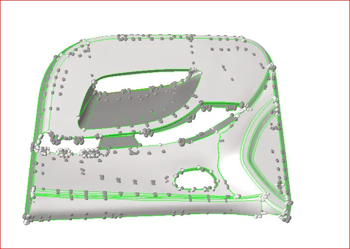
8.2_ Select surface by using face option
(Fig-53)

(Fig-54)
8.3_ We need only for offset surface, so hear offset only duplicate in the current component
SURFACE > DUPLICATE > CURRENT COMPONENT

(Fig-55)

(Fig-56)
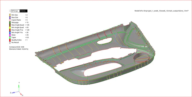
8.4_ Now done midsurface for interior trim panel inside door component
(Fig-57)
STEP_9 Starting Mesh
- Before starting mesh doing some basic steps
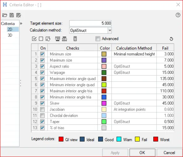
- The pathway to create the Criteria File: Preference → Criteria File Settings (ref fig-58).
- After clicking the option, Criteria File settings dialogue box will pop up.
- In that we can pre determine the Mesh Quality as per our requirements.
- Click on the Save Icon to save the criteria file for future reference
(Fig-58)
9.1_ Ware to starting mesh on component, which place feel critical or more feature available in a component that places start component
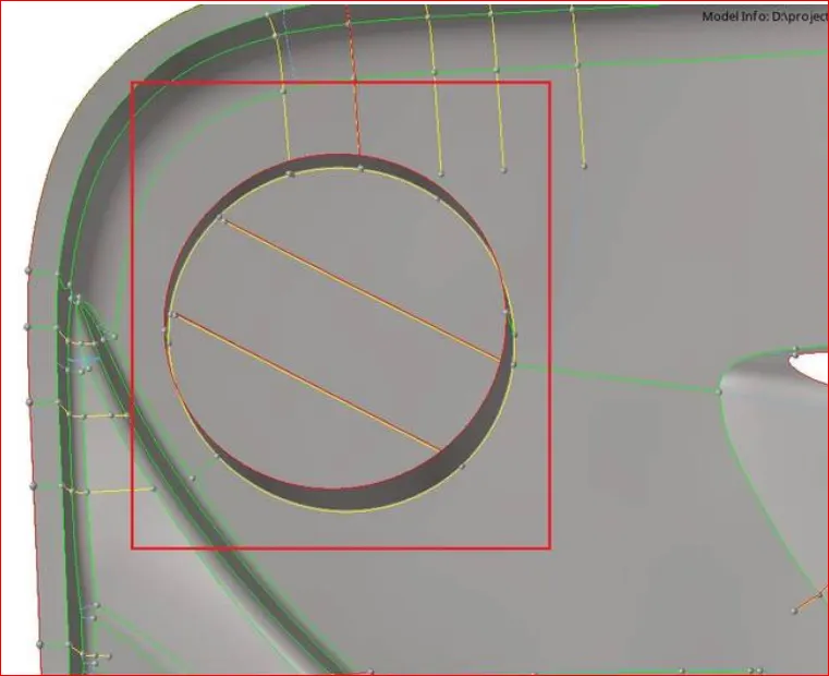
(Fig-59)
I am starting mesh from this place because this place more features available Eg; (Speaker grid, rib)
Some Conduction for other important parameters in tria management.
* no tria in corners or edge
* no opposite trias
* no back to back trias
* No trias in fillets or hemming (minimal)
* No rotational quads
* No trias should sare a Boundary with Feature line
* connectivity between the element
* Split & perform the mesh
* used mixed type mesh for irregular shaped surface & quads only for rectangular/square surface (opposite side should be parallel & equal)
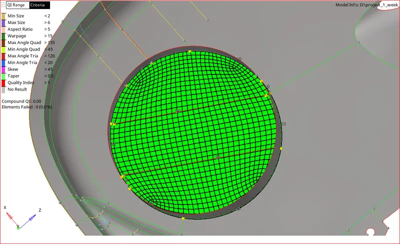
(Fig-60)
Free edge & corner place formed a lot of tria, that tria solve in the manual (ref fig_61)
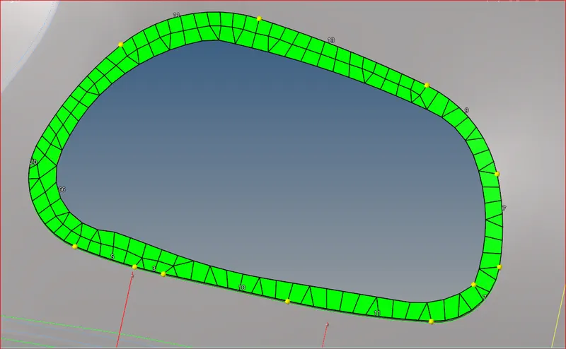
(Fig-61)
Why Remove All The Tria;
1 when we do analysis the component if you apply the force, but force not properly flow on component
2 Force flow on the direction in between any rotational available that place tria like to be a stiffer
3 main thing is a corner, rotational & opposite tria avoid in meshing time
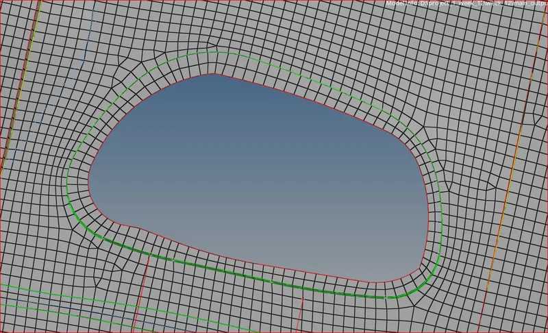
(Fig-62)
Fig-61 is before removing tria
Fig-62 is After removing tria
Drag Tria
(Fig-63)
Using Tool Drag tria 2D > qualityindex > cleanup tool
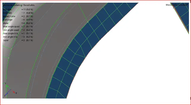
Before using the drag tool (Fig-64)
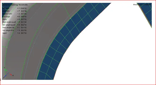
After using the drag tool (Fig-65)
Swap edge
* One element swap yo another element
Using Tool Drag tria 2D > qualityindex > cleanup tool (Fig-66)
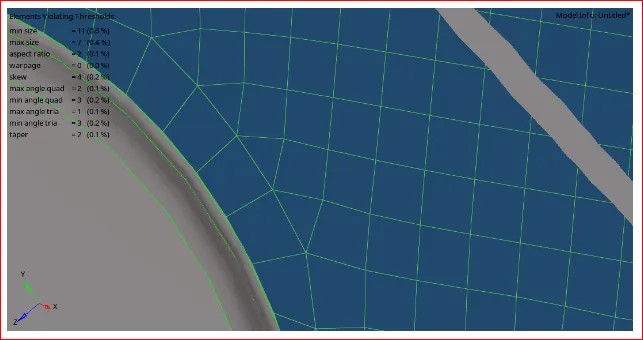
Before using the swap tool (Fig-67)
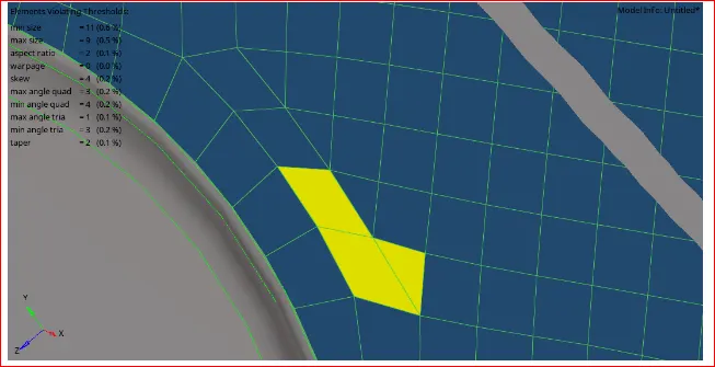
After using the swap tool (Fig-68)
smooth
* Properly align element this purpose use smooth
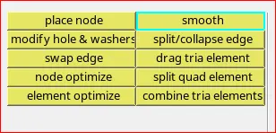
Using Tool Drag tria 2D > qualityindex > cleanup tools (Fig-69)
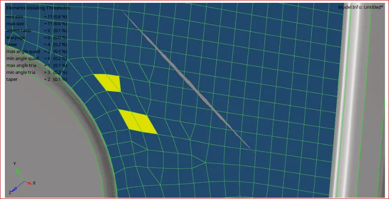
Before using smooth tool (Fig-70)
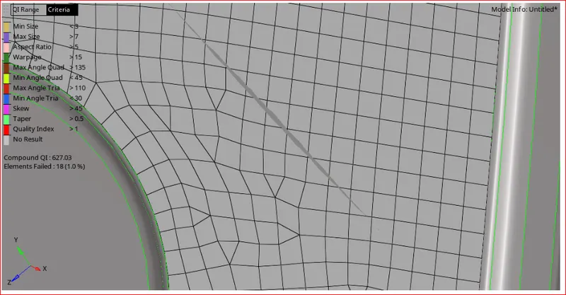
After using smooth tool (Fig-71)
Quad angle
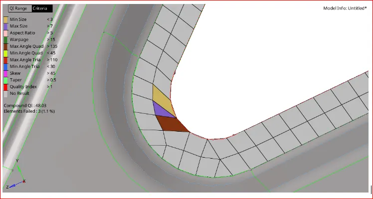
(Fig-72)
What is the maximum Quad angle;
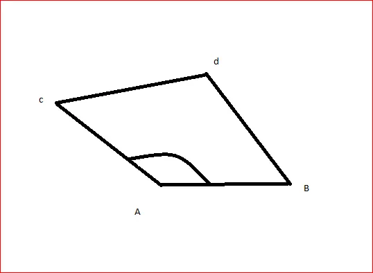
(Fig-73)
This Quad Angle Solve in threeway (color brown)
* Increase A,D Value
* Decress A,c Value
* Decrees C,D Value
Why Remove All Quad angle;
in order to capture the geometry properly have to clear all the quality parameters

(Fig-74)
What is Warpage angle
* Warp Angle is a way to measure how far is a quadrilateral element from being planar.
* When you check your mesh, Warp Angle quality measures to highlight elements exceeding the maximum warp angle.
* Warpage colour dark Green
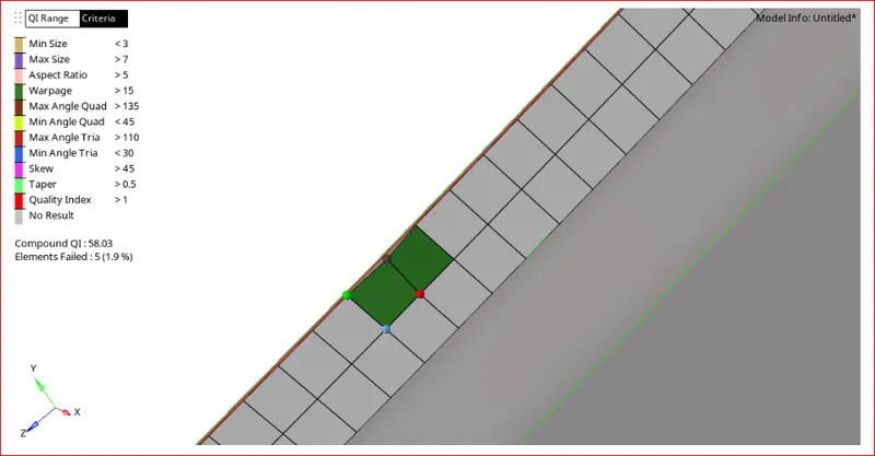
(Fig-75)
Warpage Remove tool translate opation shotcut (shift+F4), hare uasing vector opptation & magnitude value 0.1 to 0.5

(Fig-76)
Clear warpage
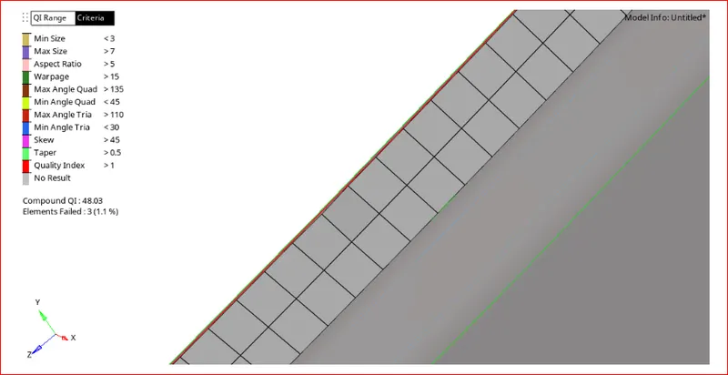
(Fig-77)
Fig-75 Warpage in element
Fig-76 is After remove Warpage in element
Done to mesh finally used smooth option shortcut (F12)
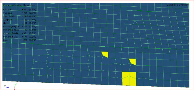
Before using smooth (Fig-78)
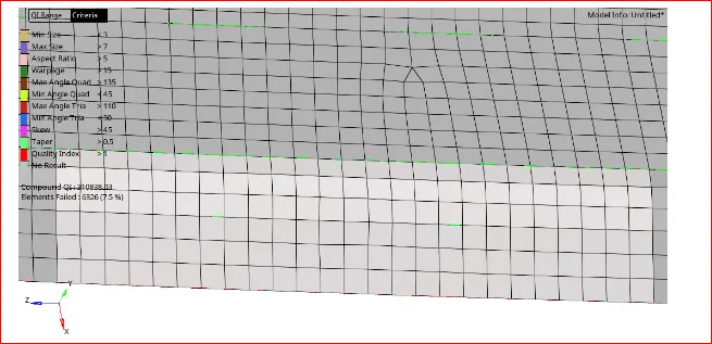
After using smooth (Fig-77)
Complete meshing Interior trim component
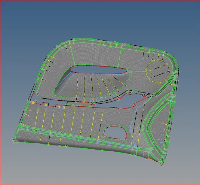
(Fig-78)
STEP-10 Assign thickness for Interior trim component
1_ Crate one component in hyper mesh tree ref (Fig_78)
2_ crate current component before creating new component
3_ move required element in crate new component ref (fig_81)
By Using TOOL > ORGANIZE > SELECT ELEMENT > MOVE
4_ Crate one Property in hyper mesh tree
5_ required thickness assign That property
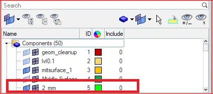
(Fig-79)
Select an element & organize that element
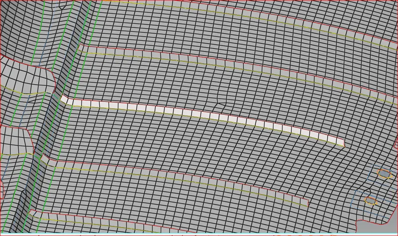
(Fig-80)
Organize element or move the element to crate component

(Fig-81)
Create one property in tree column then assign thickness for the property
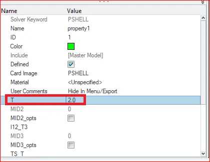
(Fig-82)
Assing thick property in component
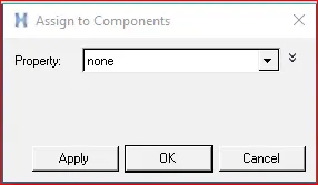
(Fig-82)
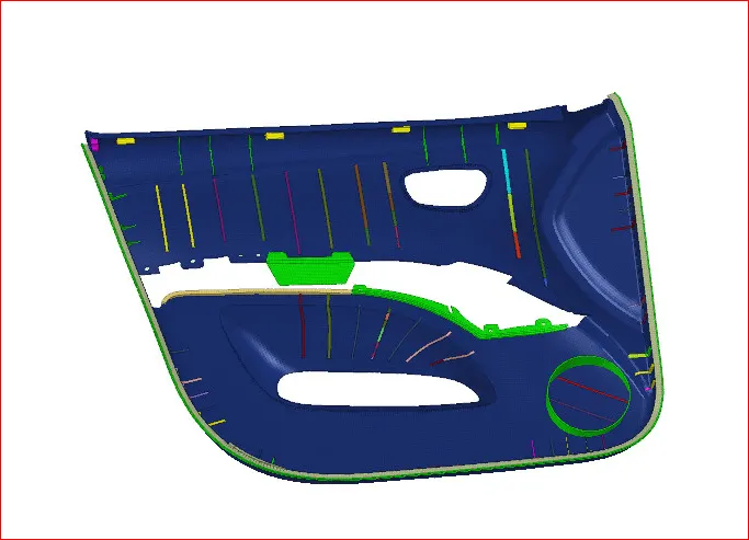
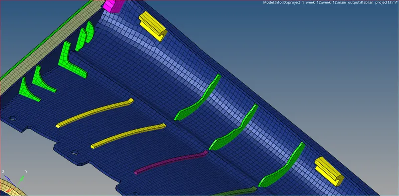
Done Assing Thickness for all component
(Fig-83)
(Fig-84)
CONCLUSION
performed meshing and assigned thickness to the side door plastic component of a car
1 From take midsurface for a given component
2 performed meshing on the extracted midsurface accounting to the given quality criteria
3 Assigned thickness of each and every component