Meshing Car spare wheel well in hypermesh (project 2)
Introduction
- It is an additional tire carried in a motor vehicle as a replacement for one that goes flat, has a blowout, or has another emergency.
- Although steel is the long-time incumbent in SWWs, for the past decade, European OEMs have been using increasing amounts of composite materials for this application to reduce weight and costs.
- By virtue of their lower specific gravity, polymer composites have generally had the advantage of lighter weight parts vs. metals.
- The spare tire is generally or almost all vehicles actually carry an entire wheel with a tire mounted on it as a spare rather than just a tire, as fitting a tire to a wheel would require a motorist to carry additional, specialized equipment
- Traditionally produced in stamped steel, and more recently in aluminum, this spare wheel well (SWW, also known as a spare wheel baffle) is a large, heavy, tub-like component that also plays a role in vehicle structure and crash safety.
- Because it is exposed to the elements, its underside is prone to corrosion
SPARE WHEEL WELL
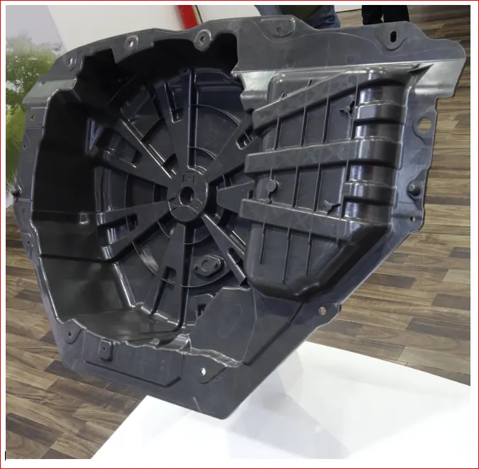
Fig_1
AIM ;
To perform Pre-processing of the wheel tub component, the step involved in the process are
1 geometry cleanup
2 Extract midsurface for a given component
3 performed meshing on the extracted midsurface accounting to the given quality criteria
4 Assign thickness for every component
STEP_1
Import model
- Import that model in hyper mesh
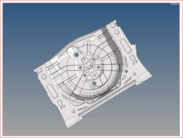
Fig_2
STEP_2
Tune on display fixed point, By using this option for visualizing a corner point
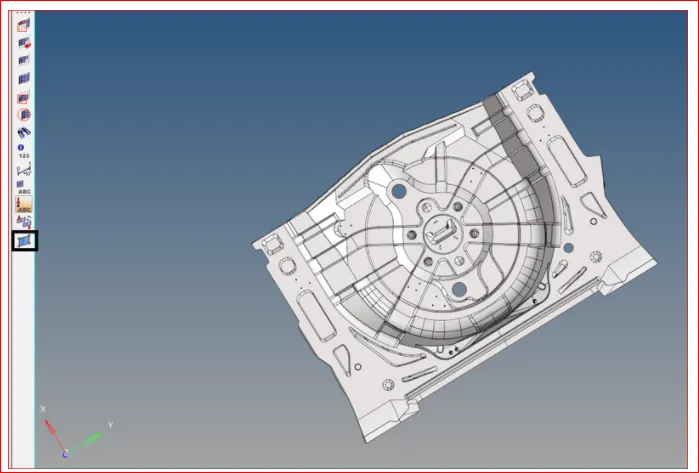
Fig_3
STEP_3
convert; Auto mode to Bytopo mode
Why the need for Converted (Auto mode to By Topo mode) is component surface visual clearly at the same time working comfort

To

STEP_4
Inspection
There is a plastic component thickness of 0.75
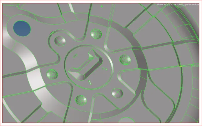
Fig_4
4.1_Free edge
Free edge in the parent component
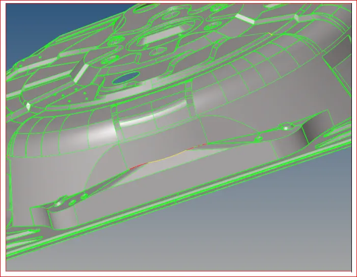
Fig_5
4.2_OPPEN SURFACE
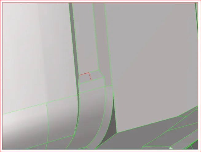
Fig_6
4.3_ More extra surface in the parent component
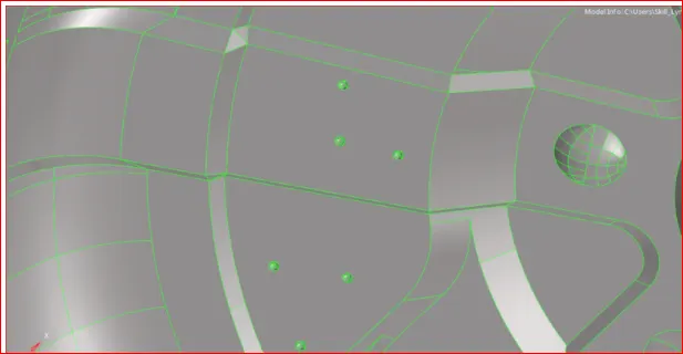
Fig_7
STEP_5 GEOMETRY CLEANUP IN PARENT SURFACE
5.1_ Delite Extra surface in parent
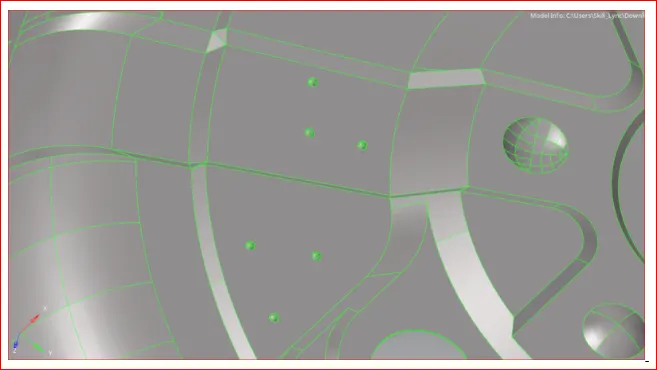
Fig_8
By Using Tool DELETE (F2) > CHANGE ELEMS TO SURFACE > SELECT SURFACE > DELETE

Fig_9
5.2_ Select surfaces
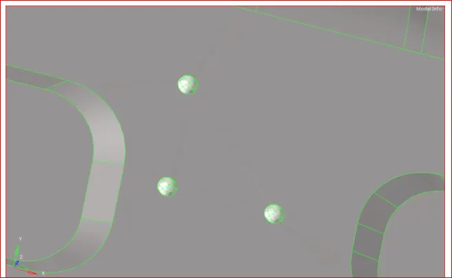
Fig_10
5.3_ Delete Surface
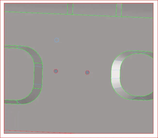
Fig_11
5.4_ By Using the fillet option fill the surface
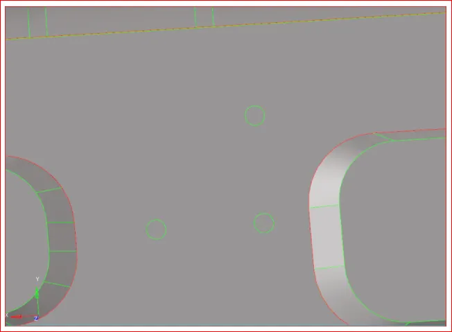
Fig_12
STEP_6 CRATE midsurface
What is midsurface?
1. Midsurface modeling is a technique for creating a simplified shell representation of a solid model.
2. Midsurface modeling can reduce the computational expense of analyzing a complete solid model when a shell model with a defined thickness and fewer details is suitable for the required analysis.
6.1_Interior trim panel bottom surface mostly same thickness so I take offset option
By Using Tool (SHIFT+F9) > OFFSET > select surface > in by face option > OFFSET

Fig_13
6.2_ Select surface by using face option
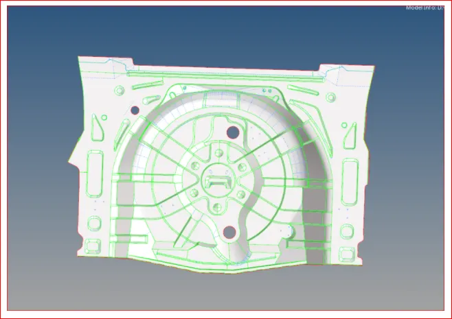
 Fig_14

(Fig-15)
6.3_ We need only for offset surface, so hear offset only duplicate in the current component
SURFACE > DUPLICATE > CURRENT COMPONENT

(Fig-16)

(Fig-17)
6.4_ Now done midsurface for interior trim panel inside door component
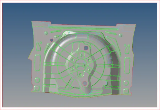
(Fig-18)
STEP- 7
GEOMETRY CLEANUP IN MIDSURFACE
What is Geometry Cleanup?
- The Geometry Cleanup option allows you to "clean up" the model geometry by merging vertices that are very close to each other into a single vertex, according to a user-definable spacing criterion.
7.1_ In Parent Component some Surface will be open, that type of surface solves to manual
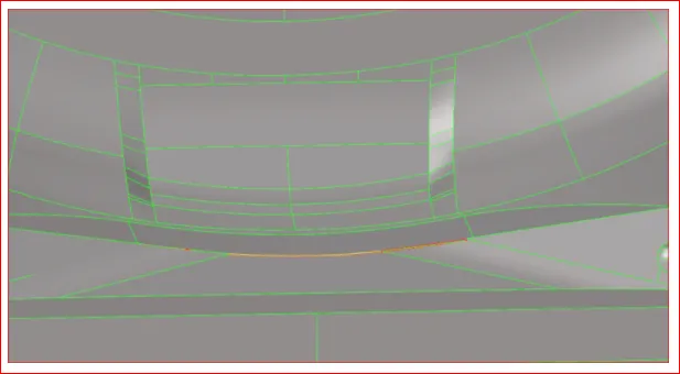
(Fig-19)
7.2_This open surface point replaces the near-surface point (or) delete surface & recreate surface. its open surface solved
By Using [QUICK EDIT > TOGGLE]
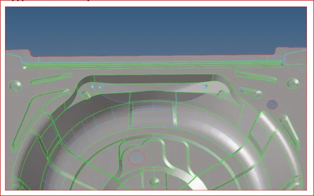
(Fig-20)
7.3_Replace project point By Using the replace tool
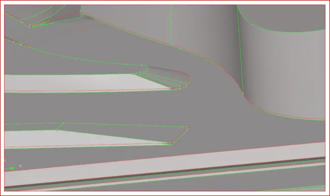
(Fig-21)
Quick Edit (F11) > replace point
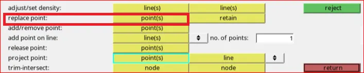
(Fig-22)
7.4_Now Done replace point, now minimum length quality criteria failing is avoid in this surface
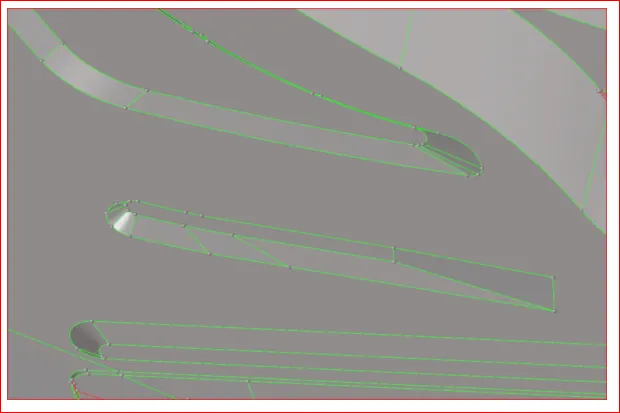
(Fig-23)
7.5_ Toggle unnecessary line in the parent component
By Using Toggle tool in (F11) QUICK EDIT > TOGGLE
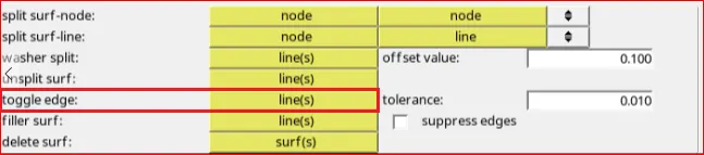
(Fig-24)
7.6_ Find out the minimum length for given quality criteria because this minimum length failing for element, so toggle the minimum length line
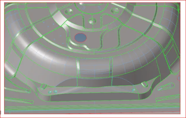
(Fig-25)
STEP_8 Starting Mesh
- Before starting mesh doing some basic steps
- The pathway to create the Criteria File: Preference → Criteria File Settings (ref fig-58).
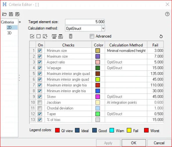
(Fig-26)
8.1_ Ware to starting mesh on component, which place feel critical or more feature available in a component that places start component
I am starting mesh from this place because this place more features available Eg; (Speaker grid, rib)
Some Conduction for other important parameters in tria management.
* no tria in corners or edge
* no opposite trias
* no back to back trias
* No trias in fillets or hemming (minimal)
* No rotational quads
* No trias should sare a Boundary with Feature line
* connectivity between the element
* Split & perform the mesh
* used mixed type mesh for irregular shaped surface & quads only for rectangular/square surface (opposite side should be parallel & equal)
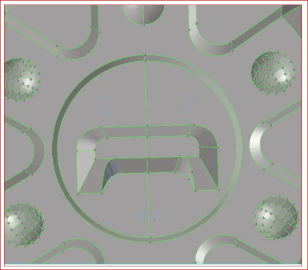
(Fig-27)
8.2_ This surface is symmetric so I split this surface working on of surface then reflect the element.
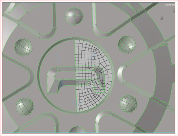
(Fig-28)
Reflecting By Using tool
[ TOOL > REFLECT > SELECT ELEMENT > SELECT BASE PONT > REFELT]

(Fig-29)
Select Element
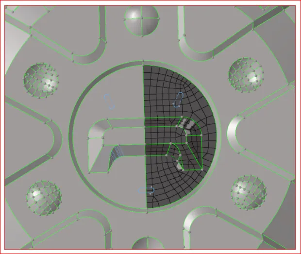
(Fig-30)
Set Axis & base point
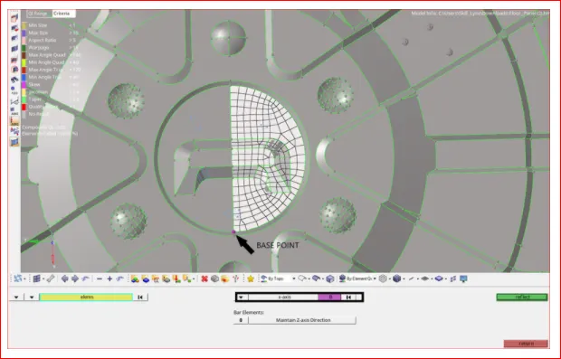
(Fig-31)
REFLET ELEMENT
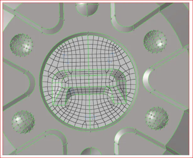
(Fig-32)
8.3_Hemi sphere surfaces, I will use to position tool
- This position tool advantage, it's one himisphere meshed after position to all Hemi sphere
By Using Tool [ TOOL > POSITIONS > ELEMENT > SET FROM POINTS > SET TO POINTS POSITION]
Select element
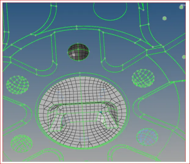
(Fig-33)
Set from point & to points
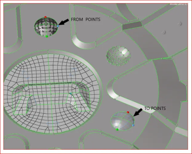
(Fig-34)
Positions The Elements

(Fig-35)
Done Positions
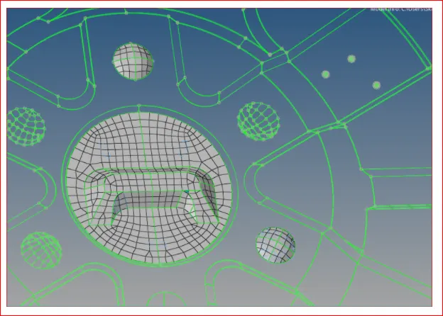
(Fig-35)
8.4_Why Remove All The Tria;
1 when we do analysis the component if you apply the force, but force not properly flow on component
2 Force flow on the direction in between any rotational available that place tria like to be a stiffer
3 main thing is a corner, rotational & opposite tria avoid in meshing time
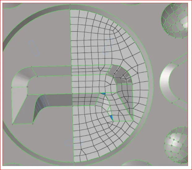
(Fig-36)
8.5_Some particular surface failing for minimum length failing for quality criteria file setting
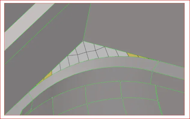
(Fig-37)
In this failing element replace by using replace option
F3 > SELECT ELEMENT END LINE 1 & 2 > REPLACE

(Fig-38)
The failing element is solved ref(fig-)
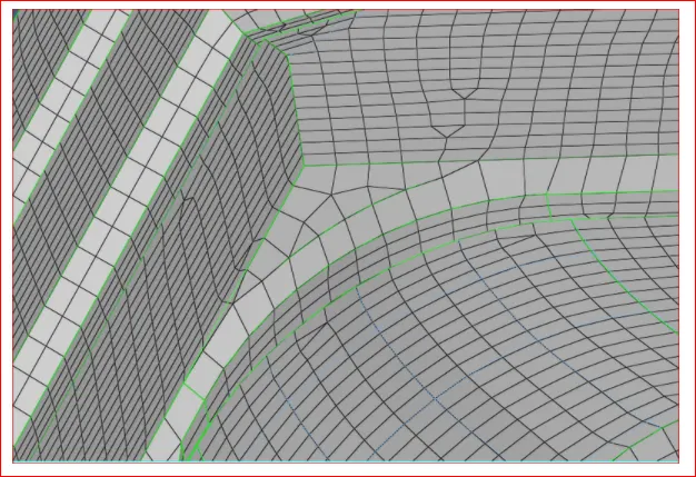
(Fig-39)
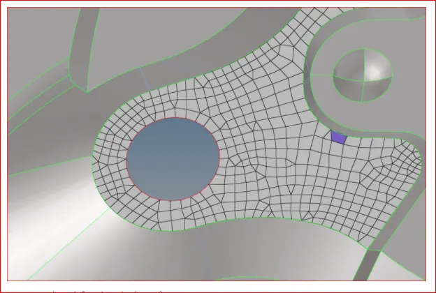
8.6_Due to the Meshing Circular surface, the mesh flow is not coming properly. ref (fig-)
(Fig-40)
8.9_ How to Crate smooth Mesh flow in a circular surface
By Using Tool (Darg, Swap, smooth & remesh)
Drag option [QUALITY INDEX]
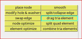
(Fig-41)
8.10_ Swap Edge option [QUALITY INDEX]
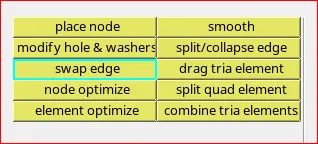
(Fig-42)
8.11_ Smooth [QUALITY INDEX]
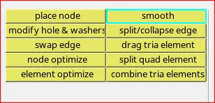
(Fig-43)
8.12_ Re-meshing [ 2D, AUTO MESH, SELECT ELEMENT, MESH]

(Fig-44)
STEP-9
9.1_Check the Tria By Using CONFIG TOOL
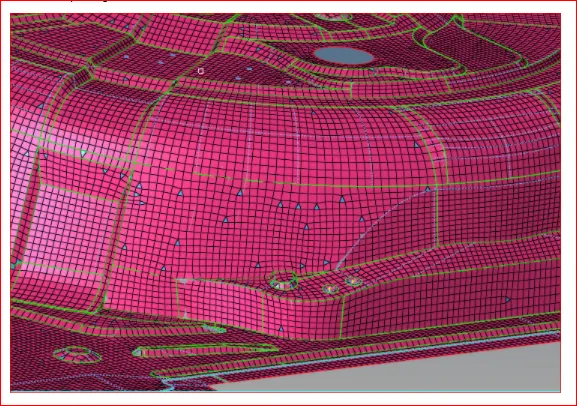
(Fig-45)
STEP- 10
10.1_FIND THE FREE EDGES
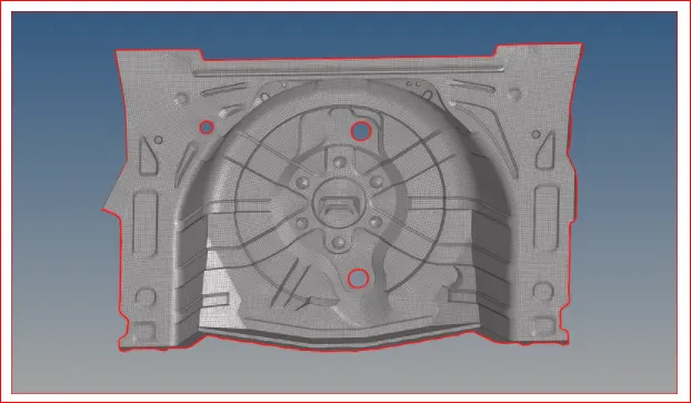
(Fig-46)
10.2_Only free edge
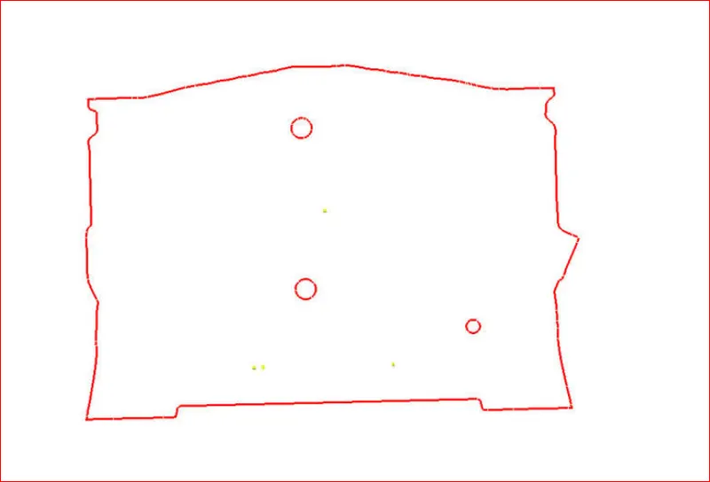
(Fig-47)
STEP-12
ASSIGN THICKNESS
1_ Crate one component in hyper mesh tree ref (Fig_78)
2_ crate current component before creating a new component
3_ move required element in crate new component ref (fig_81)
By Using TOOL > ORGANIZE > SELECT ELEMENT > MOVE
4_ Crate one Property in hyper mesh tree
5_ required thickness assign That property
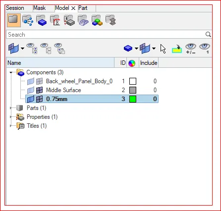
(Fig-48)
Select an element & organize that element
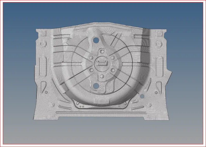
(Fig-49)
Organize element or move the element to crate component

(Fig-50)
Create one property in tree column then assign thickness for the property
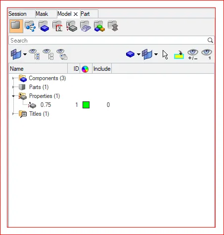
(Fig-51)
Assing thick property in component
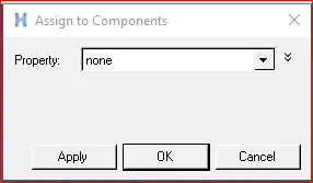
(Fig-52)
Done Assing Thickness for all component
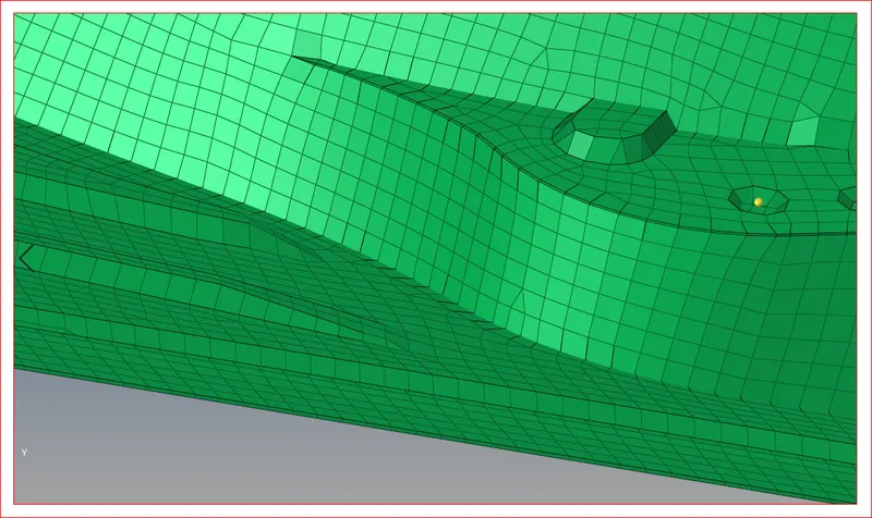
(Fig-53)
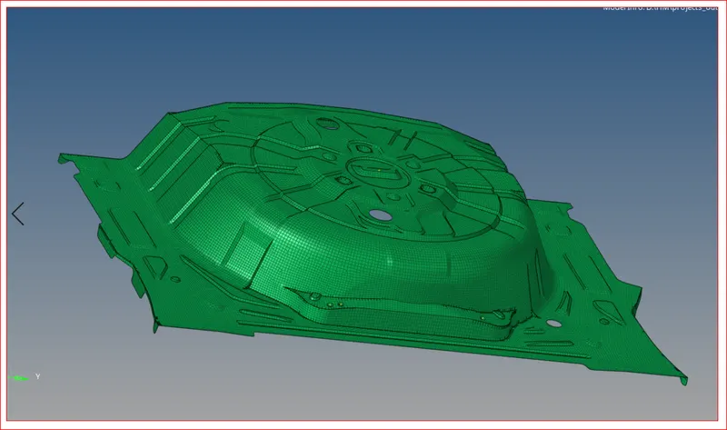
(Fig-54)
CONCLUSION
performed meshing and assigned thickness to the SPARE WHEEL component
1 From take midsurface for a given component
2 performed meshing on the extracted midsurface accounting to the given quality criteria
3 Assigned thickness for every component