Side Pole Crash of a Car using RADIOSS solver in Hypermesh
Aim,
To perform the crash analysis in the vehicle side portion only BIW (Body in wight).
Why I am selecting only the side portion, it's a reaction I am working in hyper mesh student edition it's alow only 100000 nodes
Why we are doing this numerical analysis method?..
1. Mainly This numerical method it's saving time Reduces manpower & energy.
2. This numerical method very efficient for timing consumption & cost-wise
3. If Design new compound, but don't have an idea for choosing material, so if analysis for numerical method With all material properties
4. I do it numerical analysis method, I get en number of result, so which result in our desired result pick easily.
5 so in this numerical method don't need a prototype, it's doesn't need heavy machinery help for example lathe, drilling & milling machine Etc...
6. It's very efficient for Design companies, but technical people Only working in this field.
7. If getting Result It's not 100% Aqurate but similarly 92 to 95% accurate,
In-vehicle details
1. Neon model car, I try to crash particularly front portion, this neon concept car launched in the market in 1991 under the dodge brand,
2. The Neon concept was designed by Chrysler designers who had joined the company from Chrysler's buyout of American Motors Corporation (AMC) in 1987.
Introduction
Si Crash
1. Crash car BIW (Body in wight), The vehicle’s crash analysis was used for the body structural analysis and occupant passenger behavior analysis
2. If Vehicle front poison hit a rigid wall in 35mph velocity, Some part deformation too much, for example, Vehicle shotgun poison, front rail & A-pillar.
3. All over the world industrial, the vehicle takes the crash test at 35mph it's constant.
Load distributed path.
The vehicle hit a rigid wall, the distribute acting sounding passenger area because passenger safety is very important,
Load distributed path Direction Mention Below diagram
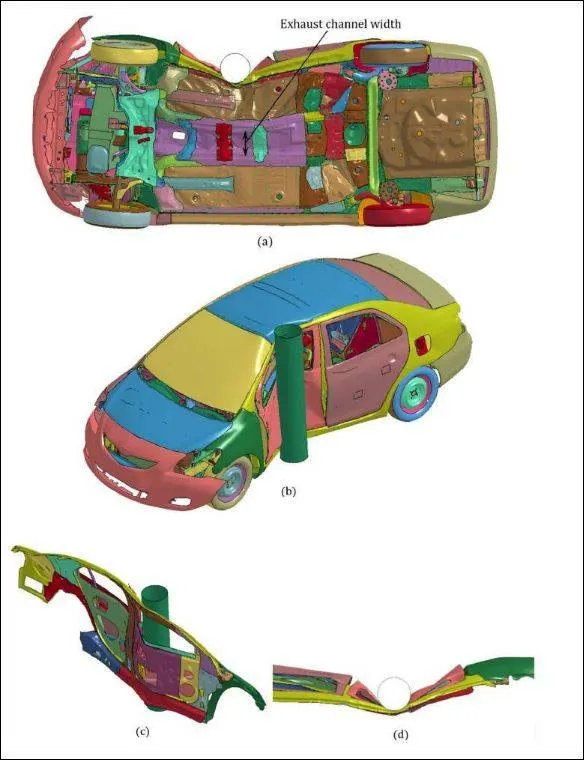
In Designer Main Task Is Force Don't Pass In The Passenger Area
Producer.
STEP 1_Unit System.
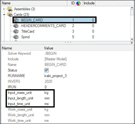
First Choose a Unit system. Here I chose mm ms kg because the unit system is very important.
Why the unit system important. an example is given add 1000kg but take unit system is gram(g) it's 1000g it's equal to 1kg
in hyper mesh unit check Cards > BEGIN_CARD > UNIT SYSTEM.
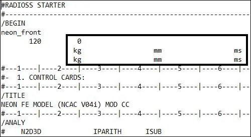
Ae if go to RADIOSS STARTER engine card, check the unit system
STEP-2
penetrations and intersection
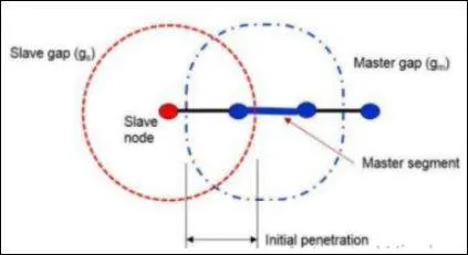
Penetration & intersection is nothing but's defined as the overlap of the material thickness of shell elements
I this case, I gap=3 resolves the issue as it takes the mesh size as well for the gap calculation
How to Resolve the penetrations
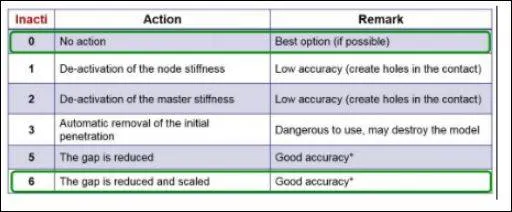
interface type-7 Inacit-6 this method penetration solve removes those penetrations and moves nodes 30% of the initial gap to avoid contact stability issue
shown below the image of penetration of the model through the thickness
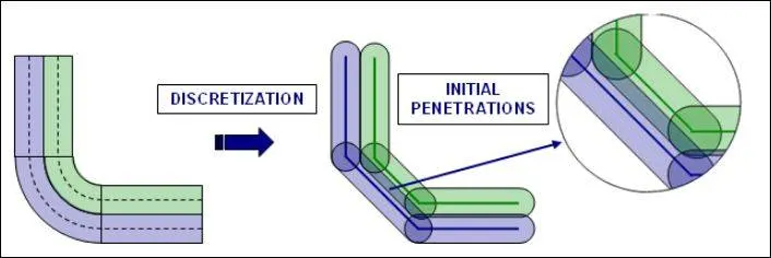
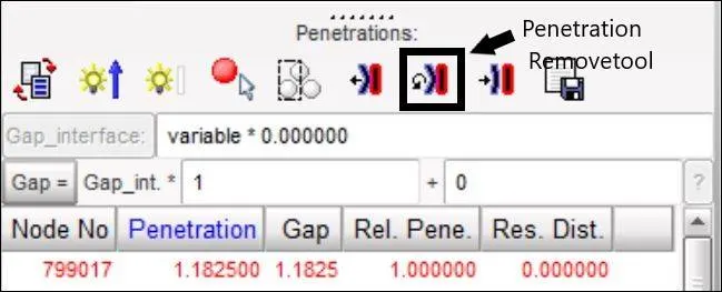
Another method Auto remove penetration method this method used in hyper-crass
STEP-3
Create an appropriate interface, with friction 0.2. and recommended parameters.
Appropriate interface with Interface gives the best result, using that interface this meaning is appropriate
I take the type-7 interface because of its variable stiffness, node to surface contact.
The search of the master or slave segment is carried out using a direct search algorithm.
Energy jumps because of the edge impact are removed cylindrical gaps around edges.
Type-7 cannot remove the initial intersection between the shells
Hyper-mesh > Model > Group > crate new interface > type-7 pusf59
hyper-cash > load case > crate interface > type 7
I crate three types of interface
1-Selfimpact
2-LH-contact_interface
3-RH-contact_interface
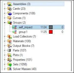
1-Selfimpact' First I crate self_impact interface, vehicle front crash in that time car body parts overlapping to other parts so that how much deformation happened, we calculate by using this self impact interface
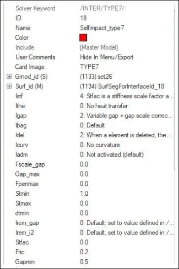
This type_7 interface some value allocate (Igap, Gapmain, Inacti-6, Istf, Iform, Stmin, Idel)
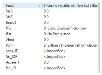
Self Impact-Slave Set Node AllCoponent
Igap= Moster node & slave node in between gap maintain this igap value
master node is parent this master deformation follows the slave node example,
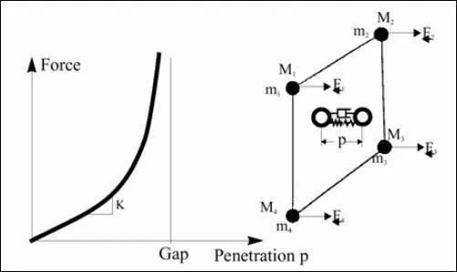
Istf=Like the other interface types, when using the penalty method, the interface has spring stiffness as a slave node penetrates the gap; however, the reaction force is computed with a much better approximation. The force variation versus penetration of a node is nonlinear, due to the increasing stiffness.
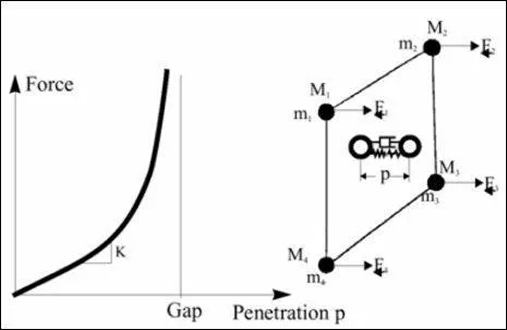
Ifri=frication
Several friction formulations are available within Radioss.
The simplest one, which is also the most used, is the Coulomb friction law.
This formulation provides accurate results in crash analysis and requires just one parameter
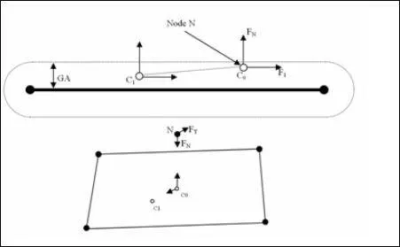
Inacti-6
The stiffness used corresponds to the curve Force versus Penetration input by you.
The instantaneous interface stiffness is the slope of the input curve at the given penetration therefore, the time step can be affected since the interface stiffness is used to compute a stable time step:
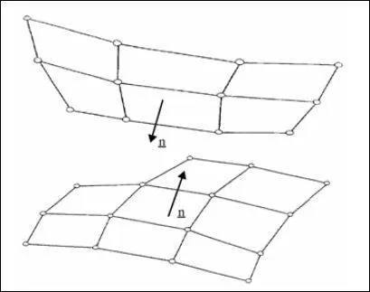
interface,Type-6 normal orientations
Idel= flange for node and segment deletion
2-when the element is deleted, the corresponding segment is removed from the master slide of the interface
Gapmain=Gap for impact activation, this Gapmain assigned for 0.5 value
Istif= Like the other interface types, when using the penalty method, the interface has spring stiffness as a slave node penetrates the gap
however, the reaction force is computed with a much better approximation.
The force variation versus penetration of a node is nonlinear, due to the increasing stiffness.
STEP-4
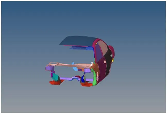
Crate self-impact inBIW part by using type-7
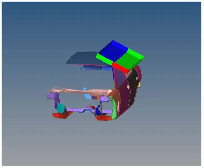
Crate impacted in master element & BIW part is a slave node by using type-7
STEP-5
Check Rigid Bodies If Any Issues
check all component & part folder, find Any unnecessary folder are both component combine in same folder clear all file
STEP-6,
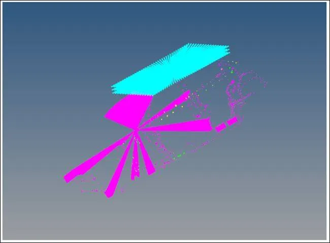
Create a rigid wall with friction 0.1.

inacti=6 is mostly using because in this the gap is reduced and scaled and accuracy is good.
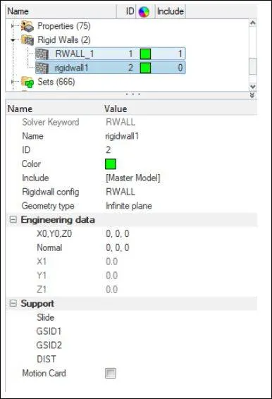
Rigid wall in this wall surface hit vehicle, rigid wall it's the master node
BCs > create > Rigid walls
Assien > Infinite plane > Set XM, YM, ZM, > Normal -1
STEP-7 Initial velocity 35 mph.
Velocity apply overall Vehicle element because a full vehicle body passed to hit one surface
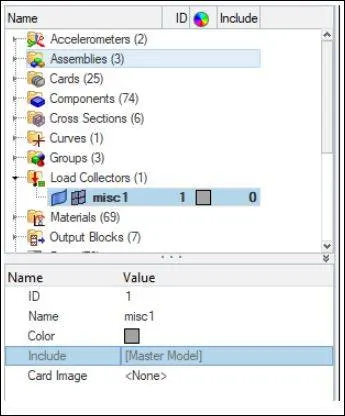
model > Load collection > creat new load case > apply velocity 15.6ms
STEP-8 CG balance
This CG maintain I am using Hyper crass, Because In hyper crash mass Madden process very easy
In-vehicle CG Acting on in the center point because CG maintains properly good results will get.
CG maintains Center in that process we some mass added in the front and backside.
Compare the model weight with the full-scale 300k nodes model and use added masses to reach the target weight of 700kg while getting CG about the required range.
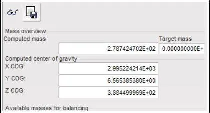
By mass distributed to each node of the node group option selecting node & increase node mass
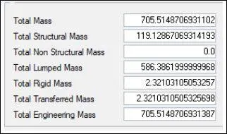
Before Add mass vehicle Total weight 146kg
After Add mass in passenger location.
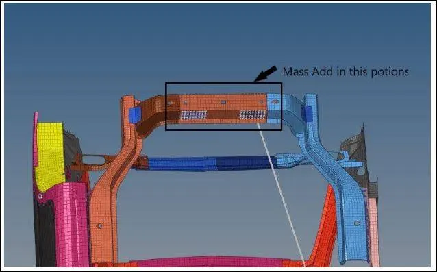
Stepney Wheel And Fuel tank Wight Add in this location
Total mass 705 I middle potion of car in BIW PART
STEP-9
Use a model checker to ensure good quality.
STEP-10
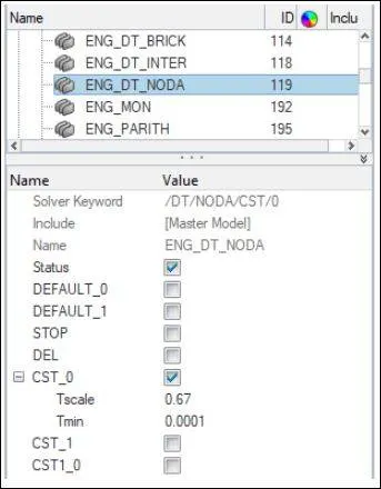
Time-step :0.5 to 0.1 microseconds. This time step allocated in eng_card in time step
Time Step in microseconds convert to millisecond (ms) x10e-3,
Take 0.5 to 0.1, so I took value 1x10e-3, so this value assigns in (CST) Constant Strain Triangle.
STEP-11
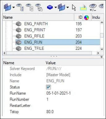
Run-80ms this value assign in Eng_card
STEP_12 [OUTPUT REQUEST]
Sectional force in the cross member.
This sectional force's main purpose, This force located in the place, we find how much force across that particular area.
Crate Section force in LH-rail, vehicle crash in that time, LH-rail compound to another compound how many force passes find out. this purpose will be used section force.
First section force in which Direction crate X, Y & Z plane, After crating all section force X, Y & Z axis like,first,crate,section,force
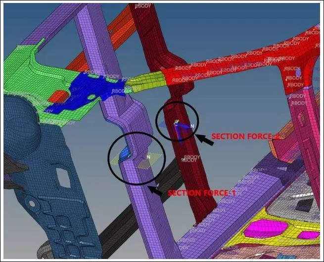
Sectional force -2 = Cross member.
Sectional force -1 = Intrusion at B pillar, hinge pillar, and fuel tank region. Provide recommendations on what can help to reduce Fuel tank intrusion.
STEP-13
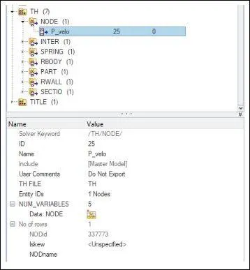
Peak velocity of the inner node of the door.
Solver > TH > NODE crate > assin pick node
This pick node purpose, in that particular node in how much force act in calculate
STEP-14
After the simulation, Any kind of result is needed in pre-registered in Solver in TH
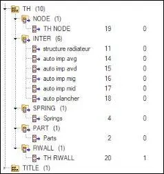
Internal kinetic energy hourglass total energy
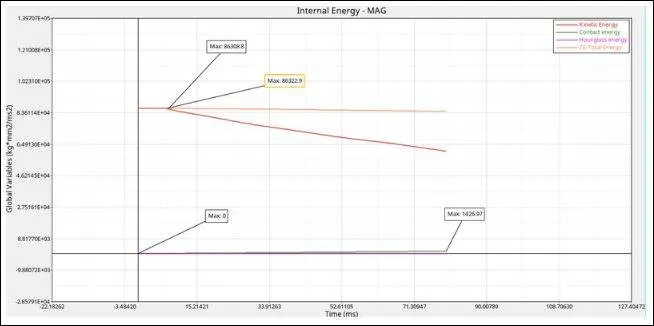
Internal Energy
- Internal Energy is the energy absorbed by the elements during deformation.
- From the simulation graph value, the load will apply on the plate that plate deformed that plate (stress & strain) increase gradually
- In this not graph gradually increase the stress value line (8403.2) the line will be nonconstant because, Crash testing in happened the front position of the car, Deformation happened nonlinearly.
kinetic Energy
- To accelerate an object we have to apply force. In kinetic maximum value(86308.8)
- To apply force, work will be done. When work is done on the object, energy is transferred and the object now moves with a new constant speed.
- The energy that is transferred is known as kinetic energy and it depends on the mass and speed achieved.
Contact Energy
- The element doesn't contact another element in deformation
- Deformation will be an increase Contact energy also increases
- Maximum energy absorption in that specimen with minimum contact energy(1426.97)
Total energy
- TE=Internal energy+Kinitic energy+External work. In Total Energy value(823222.9)
- The total energy will be constant Because internal energy & kinetic energy almost value increases gradually
Hourglass Energy
- In Crash time Deformation Will be Happen, but In result The stress printing 0 value, stress value, not mention in the result
- Hourglass Value compare Total energy Verry less so this hourglass value negligible
- In Hourglass energy maximum value(0)
Interface self impact
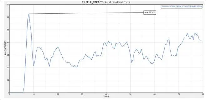
- vehicle crash in that time Vehicle element deformation to self contact.
- The car hit some wall, the first bumper hit that wall bumper connects with bulkhead, bulkhead > frame & Flore > Frame (Flore structure & panel) > Flore structure (wheel axil). like Every Part Mounted with Another part.
- So self impact in Load distributed also like this chine link, In this case, the maximum value (62.7855)
- Those all reactions to the crash value increase & Suddenly reduce but the graph value step by step increases.
Intrusions spring
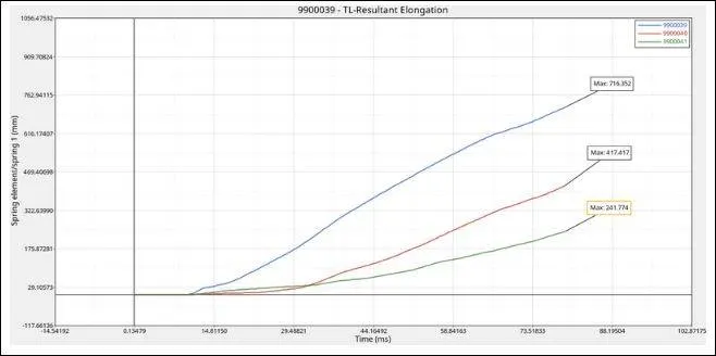
- Intrusions Spring This main purpose, in-vehicle crash time human artificial robot placed in the sidecar, so vehicle crash that time how many load act on the human artificial robot find used this intrusion spring
- In numerical method find out. how many force Act in Driver Cabine Are passenger cabin, this purpose used for intrusion spring
- This spring Acting, One spring end how many level force acts that same level force act Spring another end.
- In This case, I am assigned intrusions, in the drivel accelerated, brake & clutch padel control system to driver seat mounting place, so intrusion spring assigned place deformation act gradually. This reaction for graph value increases gradually in graph sheat.
- Impacter moving Distance finds out we assigned one spring that spring maximum value(716.325). In the First spring maximum value (417.417), in the second spring maximum value is (241.774)
Section Force Behind Driver-side
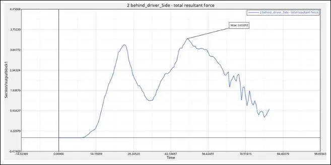
- Sectio rail(LH Door To RH Door) In Side crash How many force Acting in this passenger Section We find Out used his instruction spring
- In Crash time maximum force accessed in this rail component.
- So in graph first increase value (20ms) vehicle crash in that time bumper affecting first so that value mentions the graph, in graph pick point It's rail part deformation that value.
- This LH, RH deformation will be acting not gradually but not bad, In the graph, value increase linear, in LH & RH Both value increase in similar. but side deformation happened simular.
- In pick point maximum value (3.43212)
Section Force acting in bellow in B-Pillar Cross Section
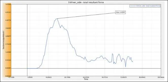
- The intrusion at B pillar, hinge pillar, and fuel tank region. Provide recommendation on what can help to reduce Fuel tank intrusion,
- Deformation that time both sides how many force passed in calculating used section method
- In-vehicle left & right side Both Side Available in shotgun part, in-vehicle Front Crash in that time Front rail & Shotgun Pannal this two-part Absorbe more shock & vibration.
- In this case, the Maximum value is(4.40907),
Conclusion:
I would like to state that this project helps me gain perspective helped me gain on frontal crash simulation, and how to extract different data points from the simulation for the after studey.
Learning points:
a. In Front Position Crash In 35mph, I learn, How deforming act Step by step, hoe load Will Passed from one part to another part.
b. What we do in front position Passenger safety increase, Simentinessly vehicle Overall mass Also Consider.
c. I Learning why graph value is increase & Decrees. Example; Accelerometer, Section, etc.