Week 9 - Challenge 3 - Bumper
BUMPER DESIGN FROM CLASS A SURFACE
1. Tooling Axis
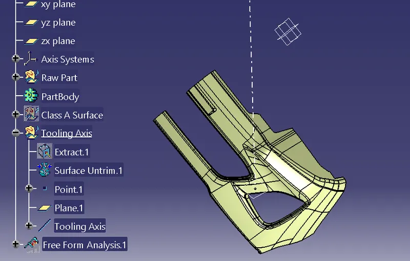
The side bumber cover given in the part file has features with cutouts to fit the front radiator and headlamp. Tooling axis for this part is decided after considering the ease of removal after deep drawing/ blanking. The relatively flat part between the head lamp and radiator is decided to be the reference for the tooling axis. This is decided based on the fact that the bumber visibility area is heighest normal to this surface.
The surface is extracted and untrimed, then it is marked with a point at it's center. A plane is created tangent to the surface and with that point as the reference. The Tooling axis is normal to the surface and passing through the point. The Tooling axis is later corrected after draft analysis as shown in 3.1.
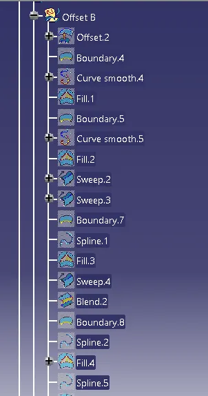
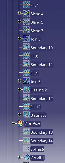
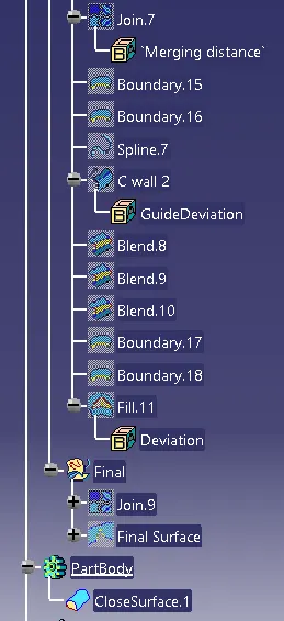
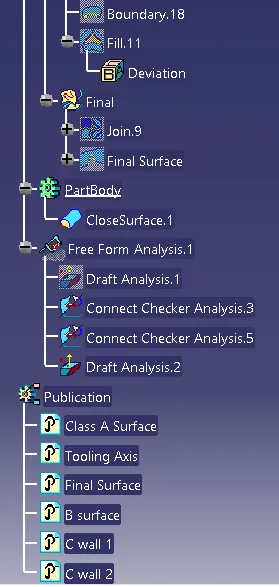
2. Part Tree Structure
3. Draft Analysis
3.1 A Surface
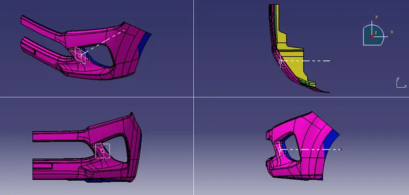
The marked blue areas in the figure below indicate the problem areas in the sheet metal part wrt tooling axis. The Big area of red and blue on right top side in the picture can be neglected becaude it is parallel to tooling axis, it could be performed separately from the other operations.
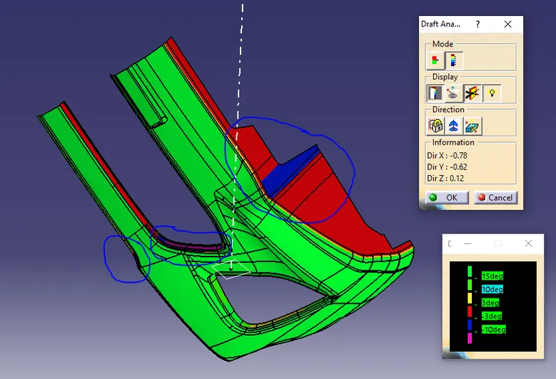
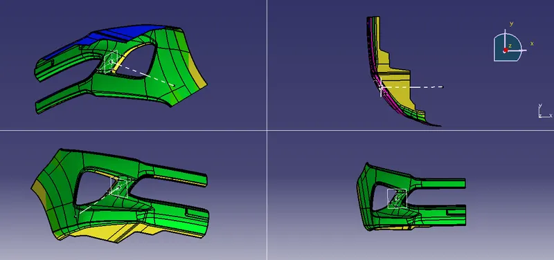
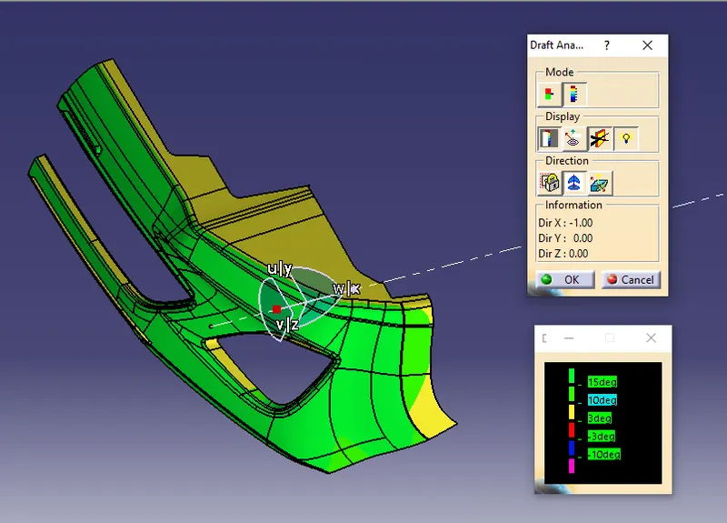
They indicate these surfaces are oriented opposite to the tooling axis draft and may be responsible for the part to be stuck or deformed during ejection of the part. In fact, they are in the way even in the deep drawing process. The solution suggested is to change the surface orientation or modify the tooling axis. Change in tooling axis means the other surface orientations must be rechecked with respect to new tooling axis. Correcting the tooling direction parallele to x axis by creating a YZ parallel plane on the point we can correct most of the drafting errors below is the corrected Tooling axis. Note there are no red areas and all drafting angles > 3deg as indicated be yellow and green surfaces. The previously red surfaces are now mostly yellow. This clarifies the design intention of the class A surface for drawing operations.
3.2 Plastic Component
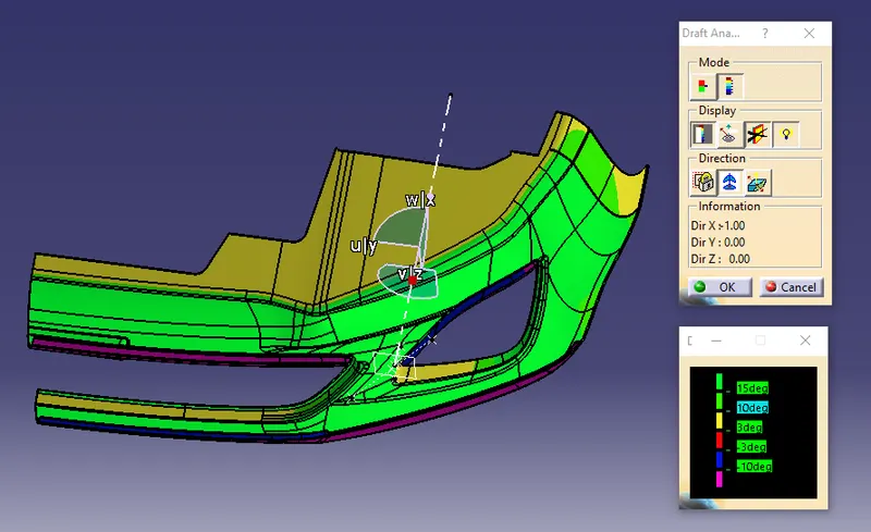
Draft Analysis of component is conducted with ful analysis mode in the draft analysis function. The results are shown in the figure below. As can be seen most of the area is green (>10deg) and there are few areas with yellow (>3deg, <10deg) color both indicate these parts are not in the way of component ejection from die. The surface resting on the drag as seen in the figure as pink (>-10deg) colour and blue (<-3deg, >-10deg), this means it is easier to remove from the drag. Hence, the part is ideal for die operations. Note there is no red anywhere indicating good tooling direction.
4. Multi- View of component