Week 9 - Challenge 1 - Base Bracket Design
BASE BRACKET DESIGN - TOOLING AXIS AND CLASS C SURFACE
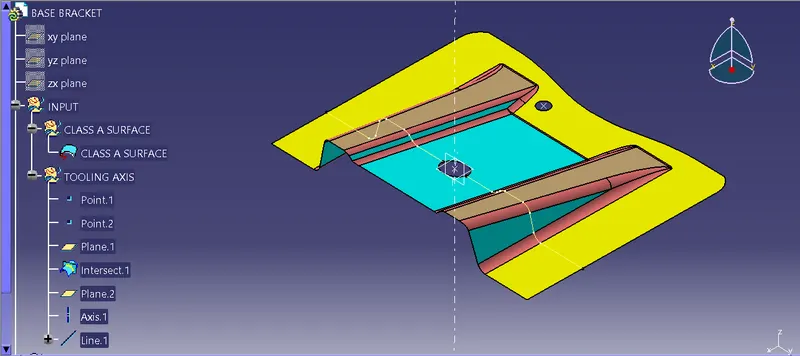
1.1 Tooling axis creation with Part Tree Structure(PTS)
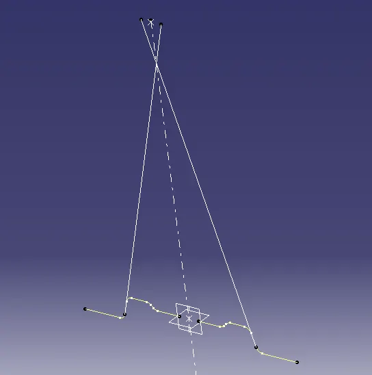
- The Point 2 is located by the center point of the locating hole. Point 2 is used to crate a plane 1 parallele to ZY plane.
- Plane 1 is used to intersect the Class A surface. Two Angular lines on the Profile are extented. Their Bisection point is used to create a point.
- The two points are joined to form a Axis line.
- An Axis is created passing through the point and center point.
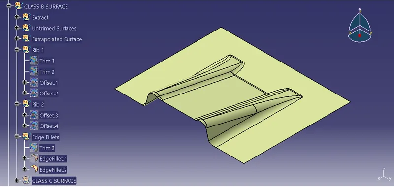
1.2 Class B Surface with PTS
1.3 Class A Surface and Plastic part
1.3.1 Class A Surface with PTS
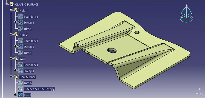
1.3.2 Plastic part
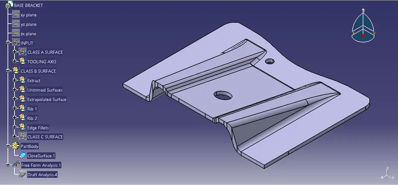
1.4 Draft Analysis of Class A Surface
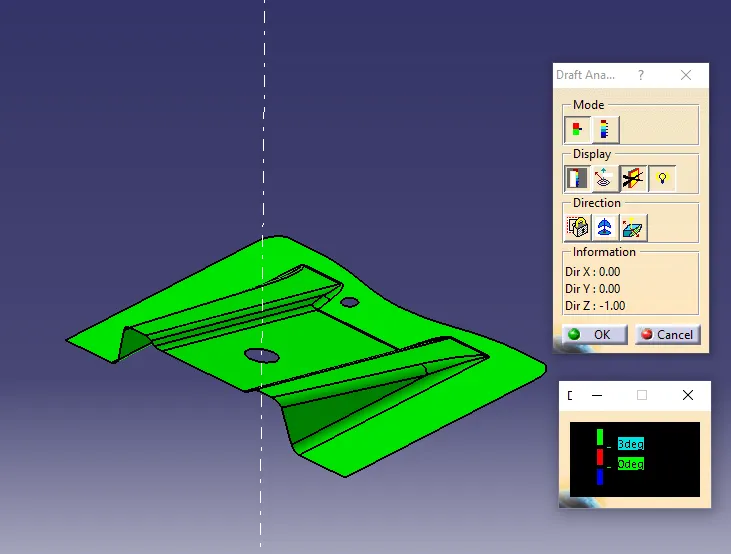
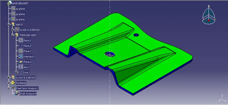
1.5 Draft Analysis of plastic part wrt Tooling Axis
1.5.1 Draft Analysis
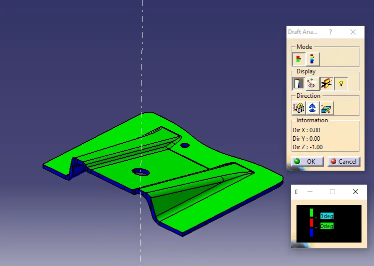
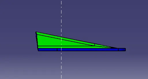
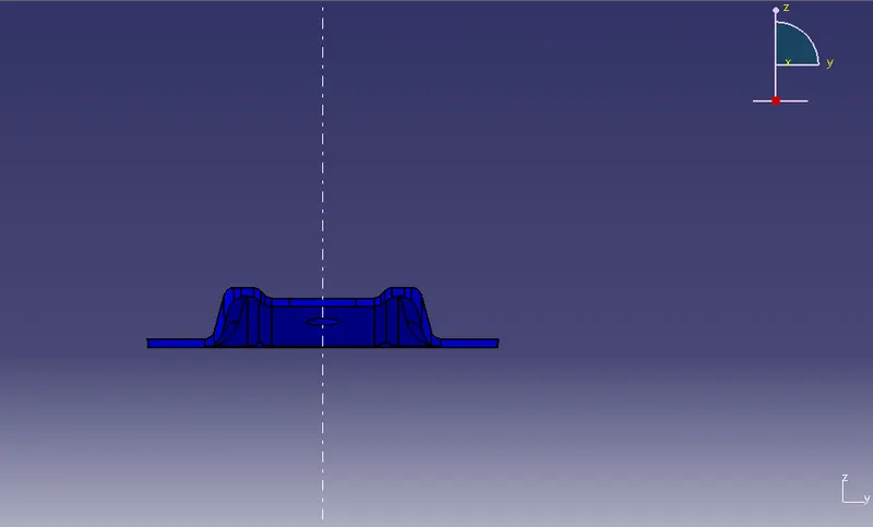
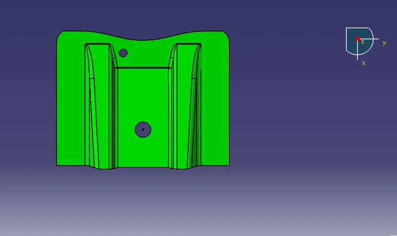
- Draft Analysis revealed a Green top surface with draft angles >3deg and Wall surface with a draft angle of -3deg(inside).
- This is done to facilitate part removal from mold.
1.5.2 Isometric view
1.5.3 Front view
1.5.4 Top view
1.5.5 Side view