Advanced Sheet Metal Design Using NX Cad Challenge_6_Bracket
Creating a Bracket Using NX
Objective
To creat a bracket with given drawing and directions. To draft the Metal.
Introduction
A metal bracket is a fastener or connector designed to secure and hold two pieces or objects together. They are used to support shelves, stabilize equipment, fasten uprights, or serve as decorative accents. Metal brackets come with or without holes and can be threaded to allow screws to be attached to them.
The versatility, strength, and durability of metal brackets make them adaptable to a wide range of applications from construction and manufacturing to automotive and aerospace industries. There are several methods available to manufacture metal brackets, which include CNC machining, casting, and sheet metal fabrication and stamping forming.
Several types of metals are used to produce brackets, the choice of which depends on the load, appearance, surface finish, thickness, possible angles, and cost. Materials for the manufacture of brackets include steel, stainless steel, aluminum, and brass. The most common types of brackets are L, U, and Z shaped and gusset brackets.
The many different styles, shapes, thicknesses, and metals of brackets require the use of several different manufacturing methods. The choice of production methods include casting, stamping, CNC machining, laser cutting, and extrusion. With all forms of metal brackets, finishing, which involves coating, polishing, painting, and plating, is the key to the appearance and properties of metal brackets.
Stamping or pressing forms metal brackets by transforming a flat sheet of metal into the shape of the metal bracket. Using a stamping or machining press, sheets of metal are blanked, embossed, bent, flanged, and coined. It is a flexible process that is capable of shaping any type of metal. Stamping is cost-effective and capable of rapidly producing large quantities of metal brackets.
The four main types of stamping are progressive stamping, transfer die stamping, fine blanking, and four slide stamping. Progressive stamping and transfer die stamping involve a set of stations where the piece of metal is carried from station to station and are used for metal brackets with several bends. Fine blanking is used to achieve flatness and sheared edges. With four slide stamping, four different tools shape the metal bracket at the same time.
The three types of stamping presses used for stamping are mechanical with a flywheel, hydraulic with a hydraulic cylinder with hydraulic fluid, and mechanical servo that uses an electric motor. All three types of presses use extreme force to reshape a flat sheet of metal or blank. [Full Article]
Methodology
- Sketch the section line according to given dimentions.
- Make a Contour flange from the sketch of 3mm thickness.
- Cut out the needed L shape using sketch.
- Use break corner with given radius at given points, R30 at 5 points and R60 at one point.
- Use hole to place and create all holes of 20mm dia.
- Unbend.
- Create Bead of (7+3) mm Radius(outer) and 10 mm depth(Outer), 5mm die radius.
- Rebend.
- Flat pattern.
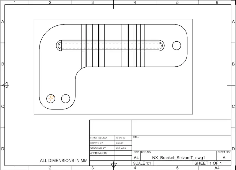
- Create New file and Draft using Base View.
Tools Used
Contour Flange
Creates a base feature by extruding a sketch along a vector, or adds material by sweeping a sketch along an edge or a chain of edges.
Normal Cutout
Use the Normal Cutout command to cut material by projecting a sketch onto the model and then cutting perpendicular to the faces intersected by the projection. You can use planar sketches or 3D curves to specify the section for the normal cutout. If the sheet metal part has multiple bodies, you can specify the target body on which you want to create the normal cutout. You can design the sheet metal part within the context of an assembly and create cutouts while the model is in the formed state. In the example, the intersection curves of the two bodies are used as input to create a normal cutout. The cutout creates a void in the pipe hanger that allows the pipe to pass through it.
Break Corner
Use the Break Corner command to round or chamfer sharp corners of a tab or flange. When you create blends on thick edges, to save design time, you can filter out invalid edges.
Hole
Adds a hole to one or more solid bodies in a part or assembly with options for counterbored, countersunk, and threaded.
Unbend
Use the Unbend command to unbend a portion of the part to construct cutout features, hole features, or deform features across a bend. You can later reform the bend to represent the true formed state of the model.
Rebend
Use the Rebend command to return an unbend feature to its previous bent state. Any features added after the unbend operation are properly repositioned during the rebend operation.
Bead
Use the Bead command to lift material along the contour of a sketch that simulates a stamping tool. Beads can also be created to stiffen sheet metal parts. You can create beads on bends in the folded or flattened state. A bead created on a bend in the folded state does not traverse the bend. You can also create beads on deform features in sheet metal parts.
Flat Pattern
Use the Flat Pattern command to create a 2D representation of the flattened 3D sheet metal part.
Base view
Use the Base command to add any standard modeling or custom view saved in a part to a drawing sheet. A single drawing sheet may contain one or more base views. From base views, you can create associated child views such as Projected, Section, and Detail views.
The Base command provides options that allow you to:
-
Add any view from the master model part, the current part, or another loaded part.
Note:When you add a view from a different part file, a new drafting component will appear in the Assembly Navigator. The drafting component is identified by the drafting component icon
 . This is a reference component only, and is not designed to participate in standard Assembly operations. For example, you can not use the Replace Component command on a drafting component.
 -
Specify the position and orientation of a view on the drawing.
-
Define the view scale and settings.
-
Control the appearance of components in views on assembly drawings.
Exploded views can only be added as base views if the exploded view resides in the part that contains the drawing. See Exploded Views in Drafting for additional information.
Model Image
Front view
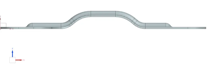
Side view
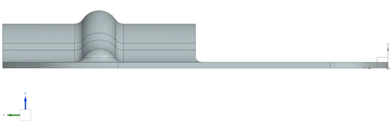
Top view
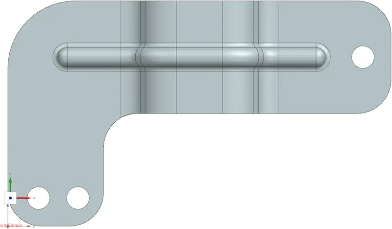
Isometric view
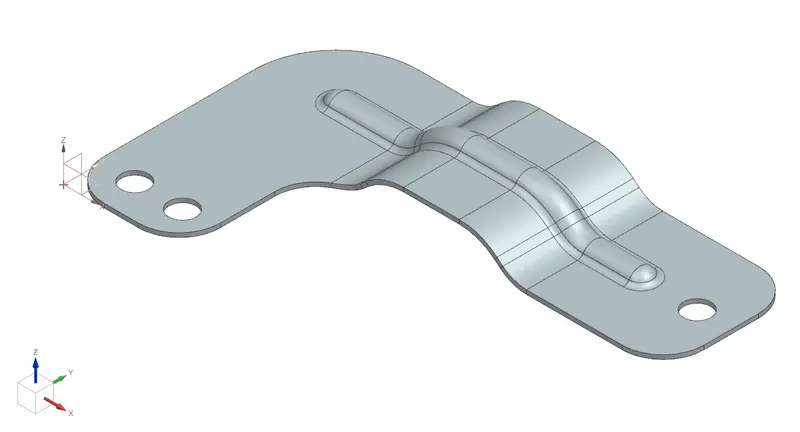
Draft
Conclusion
The Bracket is sucessfully made. Files are attached.