Week 7 Challenge - Assembly Workbench
CONSTANT VELOCITY JOINT
OBJECTIVE: Create an assembly of CV Joint using the given 2D Drawings.
PROCEDURE:
- Create a sketch using dimensions from the drawing and pad them to get a 3D model. Note: a point at origin is created and all sketchs are projected from this point.
- The three parts (Connector 1, Connector 2, Connector 3) are very simple pads taking only 3 to 4 steps. All the parts have edge fillets.
- Assembly is started with its own reference point and planes which are published. Connector 2 and 3 are required twice in the drawing. All parts include axes for every hole and shaft.
- Finally, constraints are given and the part can be moved accordingly with move command. Mostly, coincidence of axes and offset command is used in the constraints.
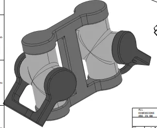
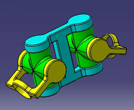
IMAGE OF INPUT AND OUTPUT:
QUICK RETURN MECHANISM
OBJECTIVE: Draw a quick return mechanism assembled using 5 body parts.
PROCEDURE:
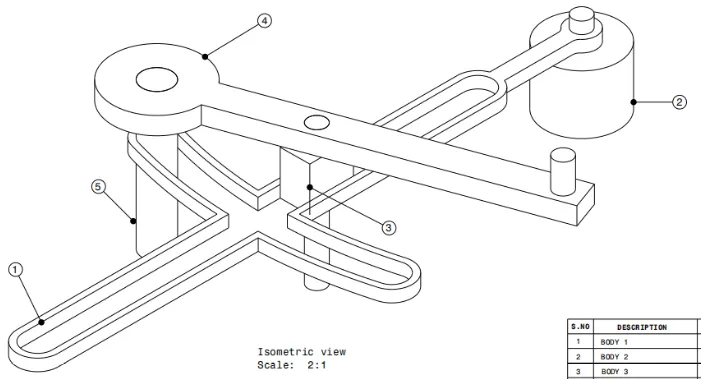
- Created the five body parts according to given dimentions. All positioned sketches is defined with projection point. The Body 1 slotted part is created using elongated hole, cylindrical elongated hole and keyhole profile. Then trim and offset command is used.
- Assembly file is opened and all the parts are inserted. Reference plane system with point is created.
- All points and axes are published.
- Constrained are applied by applying coinsidence on respective axes, offseting the Body 5 and Body 3 with respect to center and slot wall respectively.
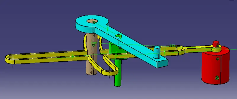
- Move command used with any axis rotation on body 3 axis, move with constrant enabled shows how the quick return mechanism will move.
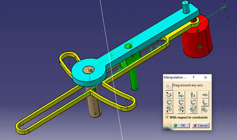
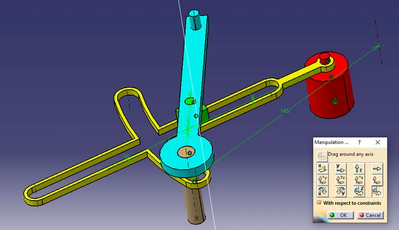
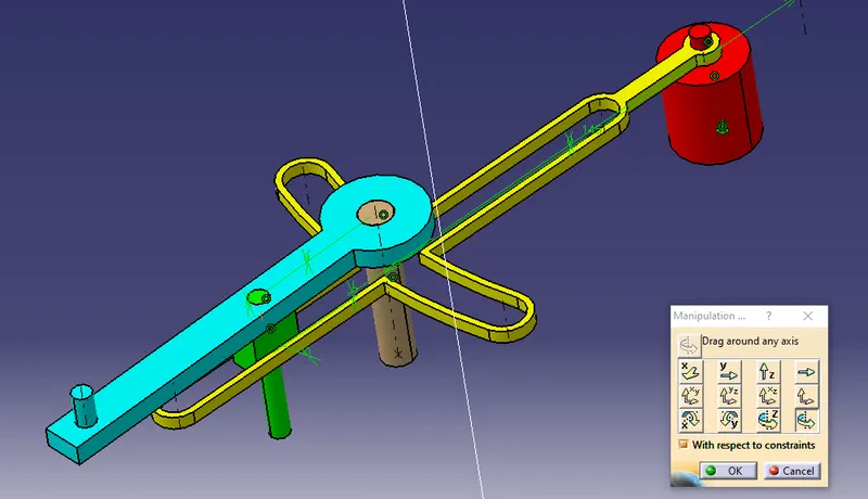
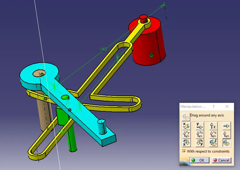
IMAGE OF 2D AND 3D VIEWS: