Roof Design
AUTOMOTIVE SHEETMETAL ROOF DESIGN USING NX CAD
1 INTRODUCTION
The objective of this project is the design and modeling of the Body-in White Roof with all design condiderations and calculation. The Car Roof serves the purpose of protecting the passengers from Weather Conditions and Accidents. The Varius types such as Convertibles, Sun-Roofs, Hardtops, etc. The basic design of the roof takes into consideration Headroom Clearance, Strength of roof and Visibility of the passenger.
2 DESIGN OF ROOF
The automotive roof is made of Roof Outer, Front Roof Rail, Bow Roof Rail(at Least 2), Center Roof Rail and Rear Roof Rail. The Sheet metal Design consideration for Draft/Deep Drawing angle is a minimum of 7deg. The Clearance between sheet metal parts for the Mastic Area is 5mm(+ sheet metal thickness x2). Heat Distortion and Snow Load Criterian Must be Satisfied to complete a Proper Roof Design.
2.1 Isometric View
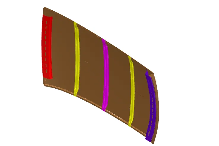
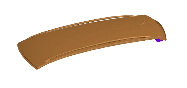
2.2 Wireframe Model
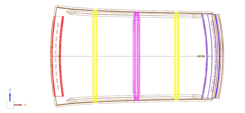

2.3 MANUFACTURING PROCESS
The automotive Roof Panels are Manufactured From Stamping Process. Most Major Problem Of this Process Is the Springback Effect. It is compensated for by Inverted Compensation Method(Ref). Roof Rails are also made by the Stamping Process. Draft Angle is given to make removal of the Sheet metal from the Die Easy.
2.4 HEAT DISTORTION CALCULATION
Heat Distortion is the Change in shape of the sheet metal part when exposed to heat from outside weather conditions. It is compensated for by the following formula.
W = [1.73 x 10^(-3) x L] + [1.85 x 10^(-8) x (R^2)/t] + [ 1.10x10^(-3) x l] - 2.68
Where,
L = Roof Length in X-Direction[mm](Roof dimension in 0-Y)
R = Roof curvature
R = 2(Rx*Ry)/(Rx+Ry)
Rx = X curvature
Ry = Y curvature
t = Roof plate thickness [mm]
l = Bow Roof Span [mm]
Judgment Condition
OK< 2.7
MOI of Bow Roof 1
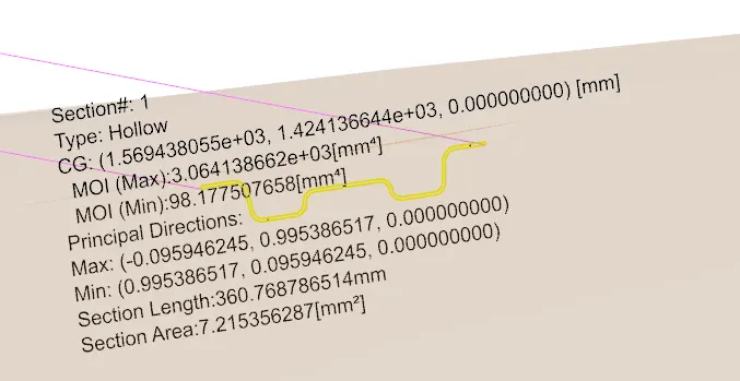
MOI of the Bow Roof 2
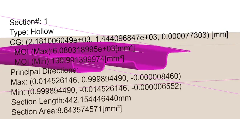
TABLE FOR HEAT DISTORTION FORMULA
| Roof Position | L | Ry | Rx | R | t | I | W | STATUS(OK<2.7) |
| Front Roof - Bow Roof 1 | 2130.9071 | 601.9579 | 2005.0558 | 925.9323637 | 0.75 | 391.8157 | 1.458614538 | OK |
| Bow Roof 1 - Center Roof | 2130.9071 | 3140.9686 | 5476.3533 | 3992.204065 | 0.75 | 431.9592 | 1.874754171 | OK |
| Center Roof - Bow Roof 2 | 2130.9071 | 4179.1975 | 10161.3428 | 5922.546506 | 0.75 | 412.354 | 2.325280425 | OK |
| Bow Roof 2 - Rear Roof | 2130.9071 | 3364.3408 | 15439.8698 | 5524.824734 | 0.75 | 328.389 | 2.120614829 | OK |
2.5 SNOW LOAD CALCULATION
The Snow Load Calculation is the measure of Load bearing Capacity of the Car roof.
Qr = [Iy x t2] / [α x s x [(Rx + Ry)/2]2 x 10-8]
Note: The Qr value given over here is correct. There was a typo error in the formula given in the video.
Where,
α = My x Lx2 x 10-12 , My = Y(Ly-Y)
t = Roof plate thickness [mm]
Ly = Distance between the front and rear roof Rails on the Vehicle along with 0Y[mm]
Length of Roof panel with the center point between Roof rail Front /Rear as the front and rear reference point.
Lx = Distance between the Left and Right end of the roof on the Roof BOW [mm]
The width of the roof panel is exposed on the surface.
Y = Distance front Front Roof Rail to Roof BOW[mm]
s = Distance for which Roof BOW bears divided load [mm]
s = L1/2 + L2/2
Iy = Geometrical moment of inertia of Roof BOW (Y cross-section )[mm4]
Rx = Lateral direction curvature radius of roof panel Y cross-section on Roof BOW [mm]
Roof panel curvature Radius of the Length Lx in Front view
Ry = Longitudinal Direction curvature radius of the Roof panel X cross-section on Roof BOW [mm]
Roof panel X curvature radius of length s in Side view
Judgment condition
Qr ≥ 3.1
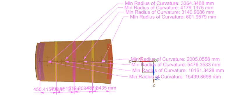
TABLE FOR SNOW LOAD FORMULA
| Roof Position | Y | Lx | Ly | My | α | s | Iy | Rx | Ry | Qr | STATUS |
| Front Roof - Bow Roof 1 | 450.4151 | 1137.4044 | 2068.2527 | 728698.484 | 0.94270905 | 411.88745 | 3.06E+03 | 2005.0558 | 601.9579 | 261 | OK |
| Bow Roof 1 - Center Roof | 1043.2663 | 1082.945 | 2068.2527 | 1069333.77 | 1.25408243 | 422.1566 | 6.08E+03 | 5479.3533 | 3140.9686 | 35 | OK |
| Center Roof - Bow Roof 2 | 1530.3098 | 1062.6592 | 2068.2527 | 823219.292 | 0.92961592 | 370.3715 | 3.09E+03 | 10161.343 | 4179.1975 | 10 | OK |
3 DRAFT ANALYSIS
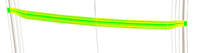
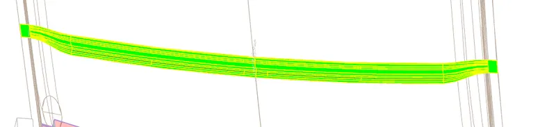
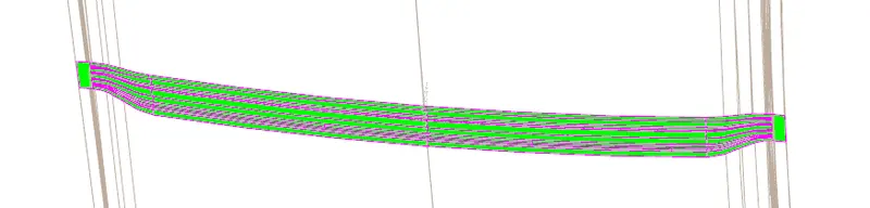
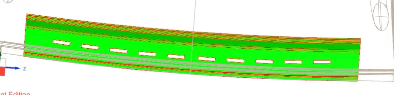
Below are the Snapshots of The Draft Analysis in Vertical(as shown) Draw Direction.
3.1 BOW ROOF RAIL 1
3.2 BOW ROOF RAIL 2
3.3 CENTER ROOF RAIL
3.4 FRONT ROOF RAIL
3.5 REAR ROOF RAIL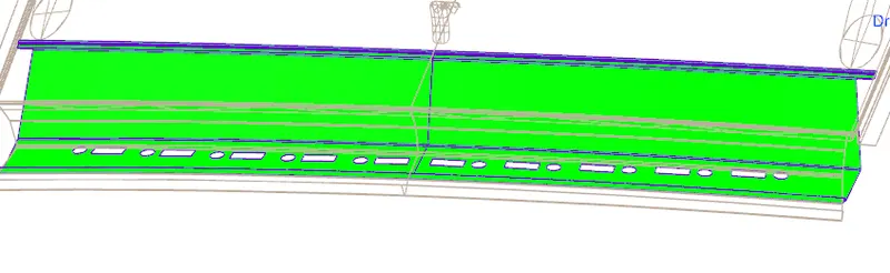
4 CONCLUSION
The Roof Design is Safe for Heat Distortion And Snow Load Criteria given. Draft Analysis of parts was also Successful. Moment of Inertia of Rails was Found using Section Inertia Analysis for all the roof rails.