Project 1
Wiring Harness Engine Assembly - Project 1
Aim: To Route the Wiring harness on Given Engine and Prepare flattened view drawing in CATIA V5. Application of all Packaging rules, Industry best practices studied in this course shall be demonstrated in design. Apply Protection coverings as required.
Introduction:
A wiring harness is a collection of electrical wires, connectors, and other components that are bundled together and used to transmit electrical power or signals within a vehicle, machinery, or other equipment. The harness helps organize and protect the wires while also ensuring they are routed safely and efficiently.
Wiring harnesses are often used in automotive, aerospace, industrial machinery, and consumer electronics. They reduce the complexity of installation and maintenance by grouping all necessary wires and connections into a single, manageable unit.
Wiring harnesses improve reliability and streamline the process of building and repairing electrical systems.(from "Wiring Harness def" on Chatgpt)
An engine harness is a specific type of wiring harness that is used in the engine compartment of a vehicle. It connects various electrical components of the engine, such as sensors, actuators, ignition systems, fuel injectors, and other key systems, to the vehicle’s main electrical system.
The engine harness is critical for managing the electrical signals and power necessary to operate and control engine functions. It ensures that electrical connections between the engine’s components are secure, organized, and protected from heat, vibration, and other environmental factors within the engine bay.
Key components typically found in an engine harness include:
- Wires – Carry electrical power and signals to various engine components.
- Connectors – Provide secure connections between the engine's components and the vehicle’s main wiring system.
- Sensors – Sensors like temperature, pressure, and oxygen sensors that provide data for the engine control unit (ECU).
- Actuators – Components like the fuel injectors, throttle body, and other parts controlled by the ECU.
- Grounding Wires – Provide a common ground path for electrical circuits in the engine.
- Insulation/Protective Sleeving – Shields the wires from extreme heat, vibrations, and potential abrasion.(From Chatgpt)
Project:
- Define the Required connectors in Electrical part design workbench and catalogue them. Do the same for protective coverings and Clips.
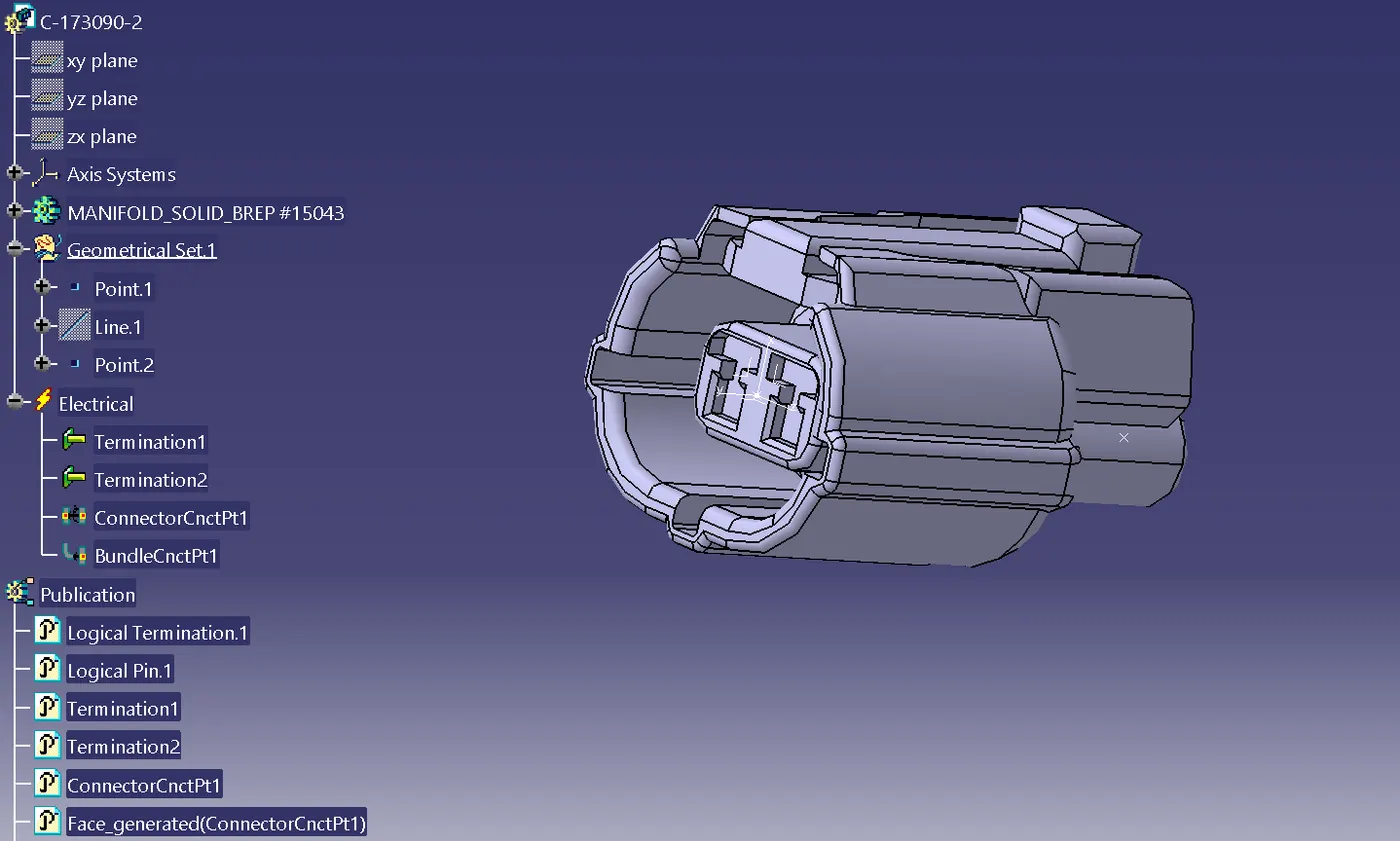

- Define Channel top as electrical mountings. Add Bundle connection points on the openings. Assemble with channel bottom. Create a another file for the Channel on another side.
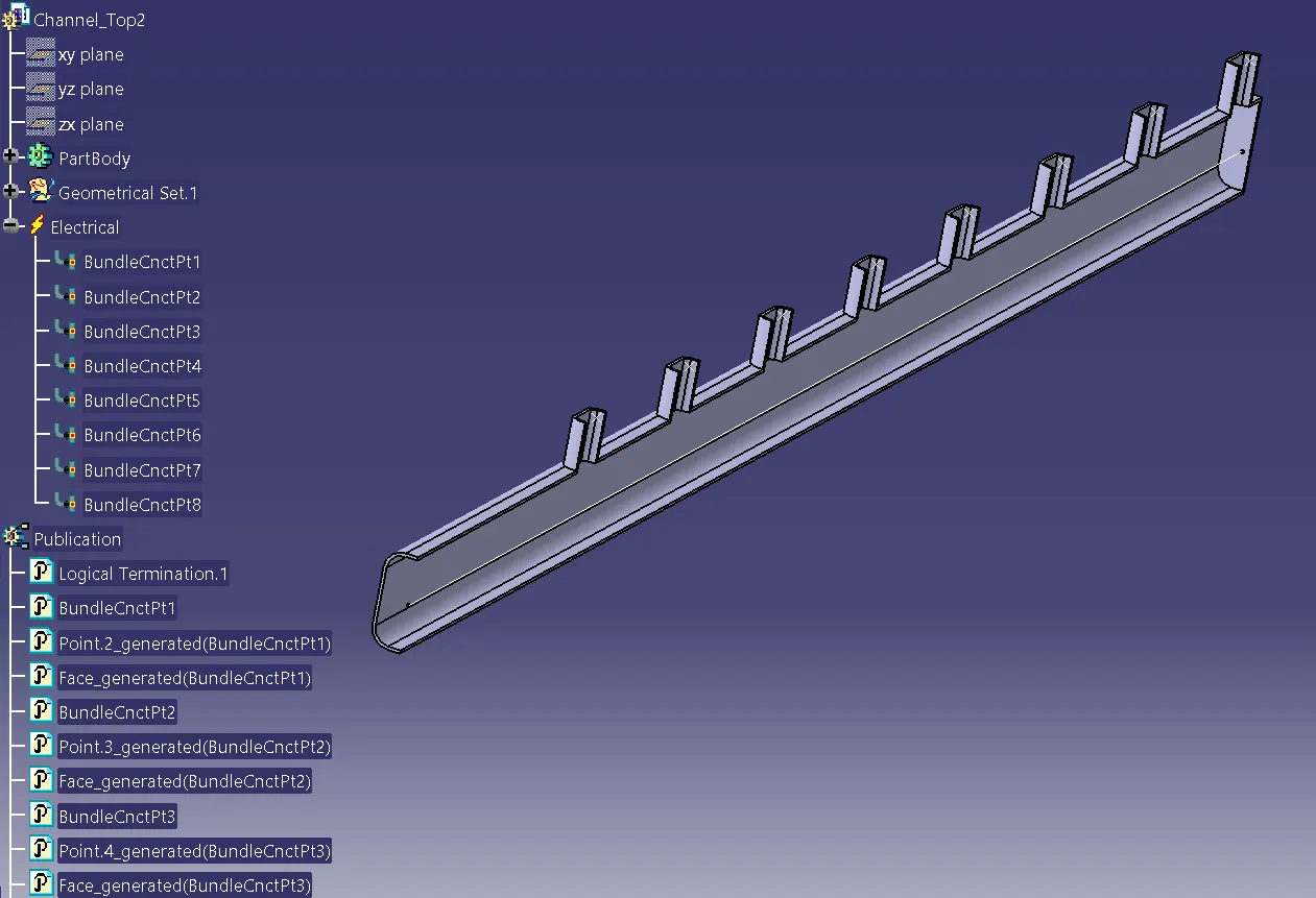
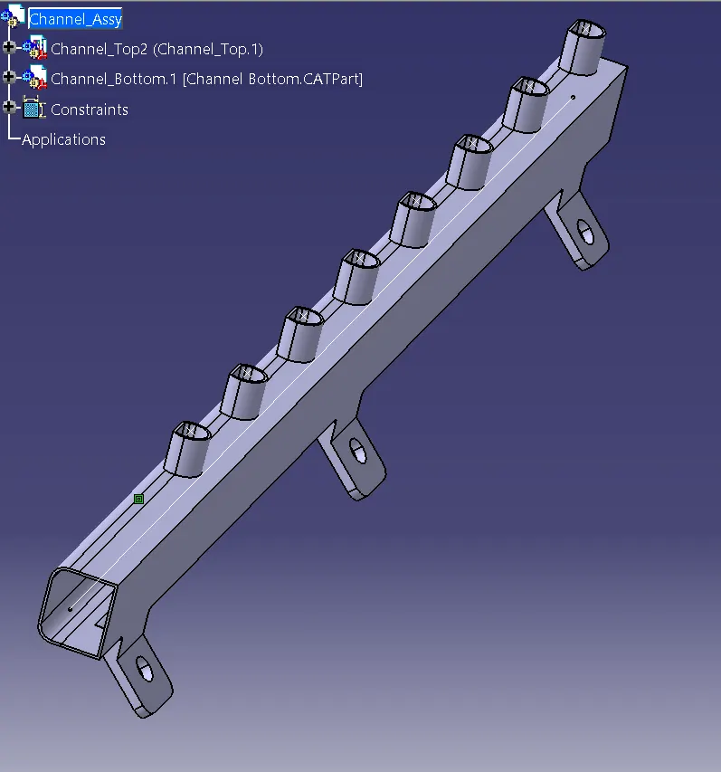
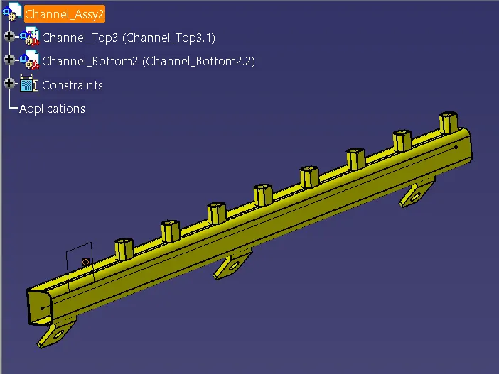
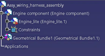
- Create Product assembly file "Assy_wiring_harness_assembly" and add the given Engine_lite to a product file under it. Create a new Product file named Geometric bundle.
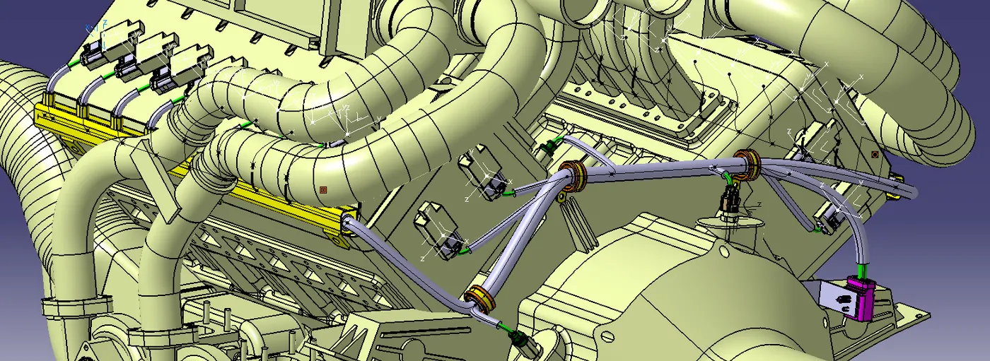
- Add the connectors to the Geometric bundle and place them on the Engine Model using Manipulation, Snap and smart move in Assembly design. Mount the 12 pole connector and its clip using a L Clip. Add P clamp in the designated areas to ensure connectivity. Mount the Channel on both sides.
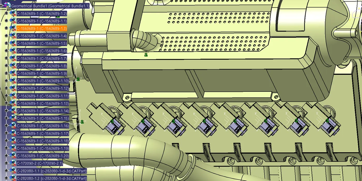
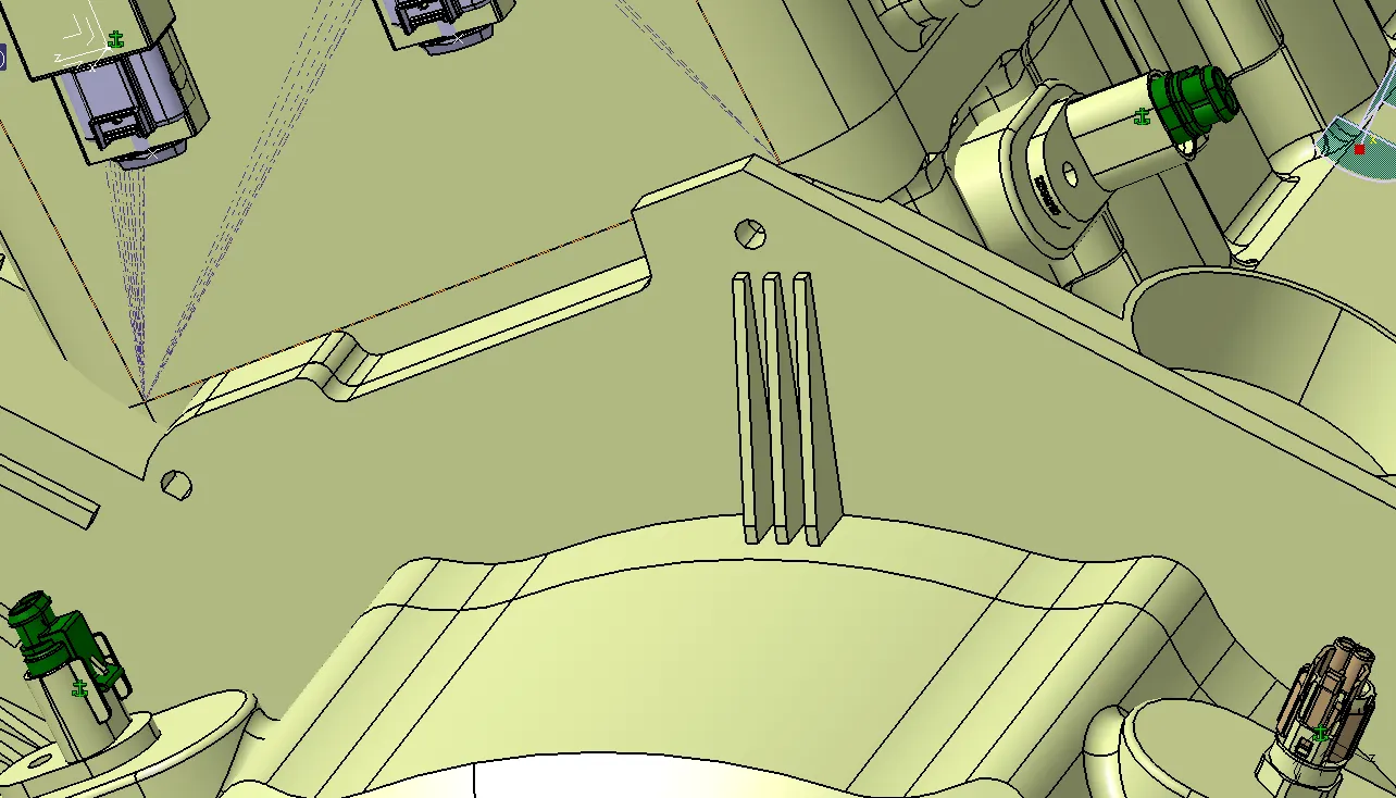
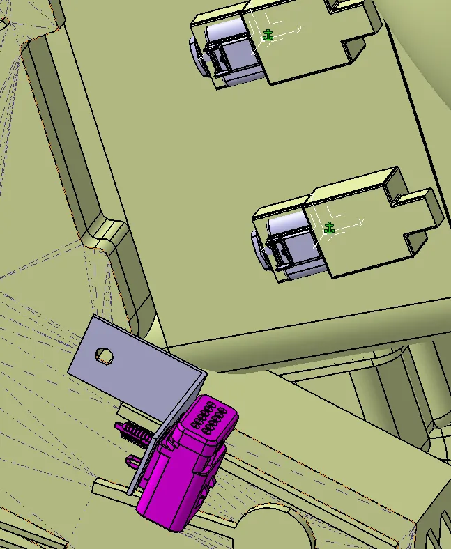
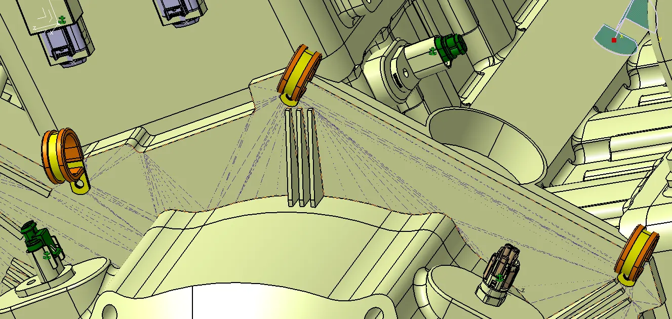
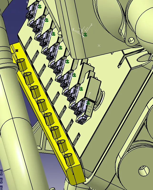
- Switch to Electrical Harness Assembly add Branchables with suitable diameter to Connect each Connector. Give slack where necessary. Add protective coverings to the Branchables. Give 20mm clearance to protective covering near connectors.
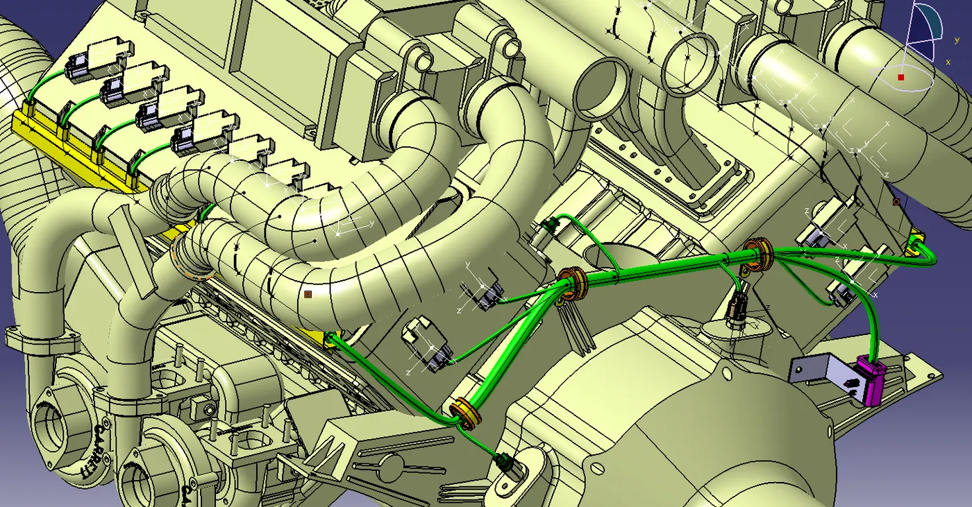
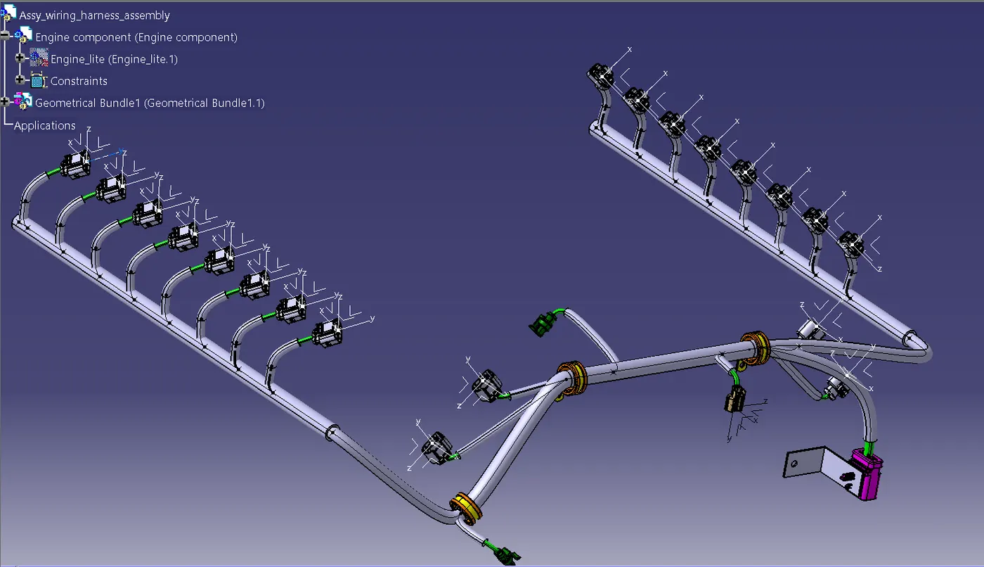
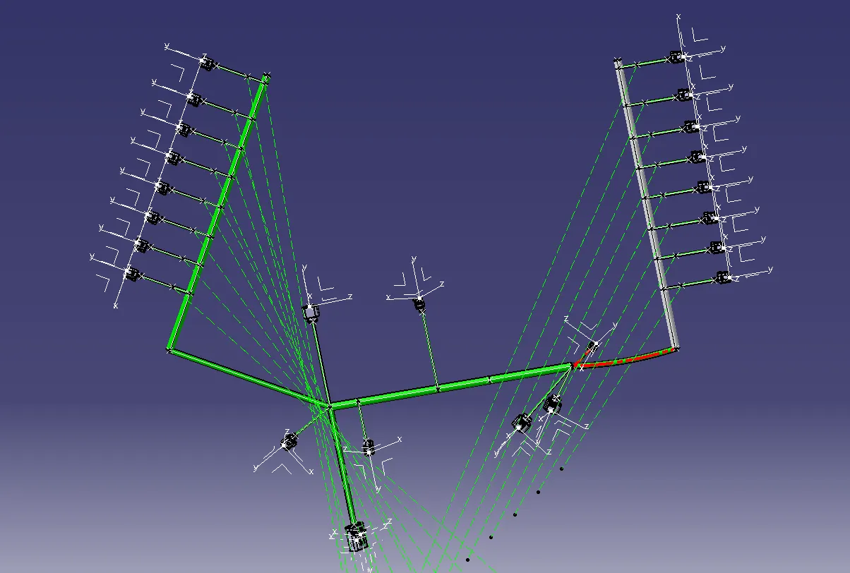
- Create Flattening model.
Conclusion: The wiring harness of the engine assembly has been completed.