Week 9 - Attachment Feature Creation - Challenge 1
Attachment Rib Feature Creation
Designing Plastic Parts For Injection Molding? Ribs Can Help Add Support And Strength.
Ribs are a feature in plastic injection molded parts. They are thin extensions that run perpendicular to a wall or plane. They are commonly used to provide additional support and strength to a part.
Thickness and location are essential to rib design. Here are some helpful design guidelines:
-
They should be designed with a thickness that is ½ the wall thickness to avoid a thick section at the wall base.
-
To minimize sink marks, design ribs that are approximately 60% of the joining wall thickness for minimum risk.
-
Best practices include spacing at a distance of at least twice the wall thickness.
-
Glossy materials require a thinner rib (40% of wall thickness).
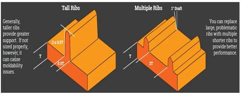
Designing with Ribs in Mind:
- The position and orientation of a rib relative to load and reaction forces is critical to its effectiveness. By being conscious of part geometry, designers can ensure that ribs added to the design will improve bending stiffness. Here are some rules of thumb to keep in mind during the design process:
Rib thickness
- Ribs should be designed to be 50-60 percent of the nominal wall thickness. Thinner does not provide much structure and may be hard to fill. Thicker ribs are tempting, but they can begin to introduce sinks on the cosmetic surface.
Rib height
- For maximum effectiveness, rib height should be no more than three times the nominal wall thickness. Since the rib will be thinner than the wall, it may be hard to fill it if it is taller.
Rib spacing
- Increase the number of ribs rather than their height in order to increase stiffness. Ribs should be spaced a minimum of two times the nominal wall thickness apart from one another.
Rib draft
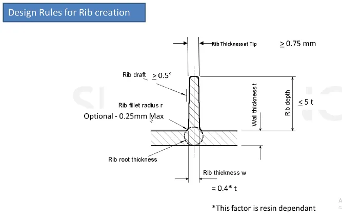
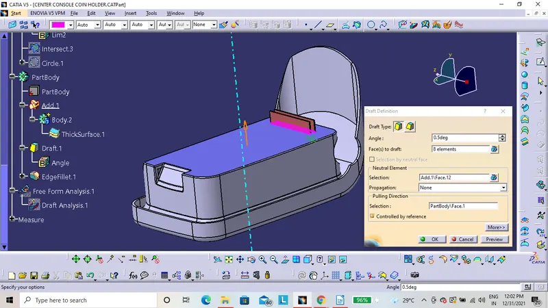
- A minimum 0.5-degree draft will ensure that they release from the tool during molding.
Rib coring
- Core thick ribs from the back or below to create a blank area and thinner rib walls. This will help mitigate cosmetic sinks.
Rib radii
- Radii at feature intersections should be a minimum of 0.5 - 1.0x nominal wall thickness to increase rib strength.
Tooling axis creation:
The tooling axis is important for removing the material when finished.
-
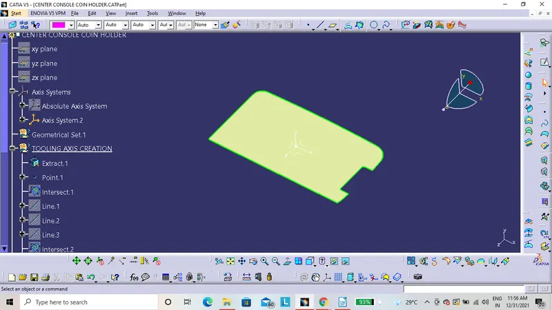
First, I will creating the point on base surface respectively also extract the surface of the component as shown in image.
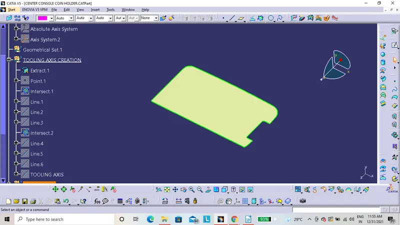
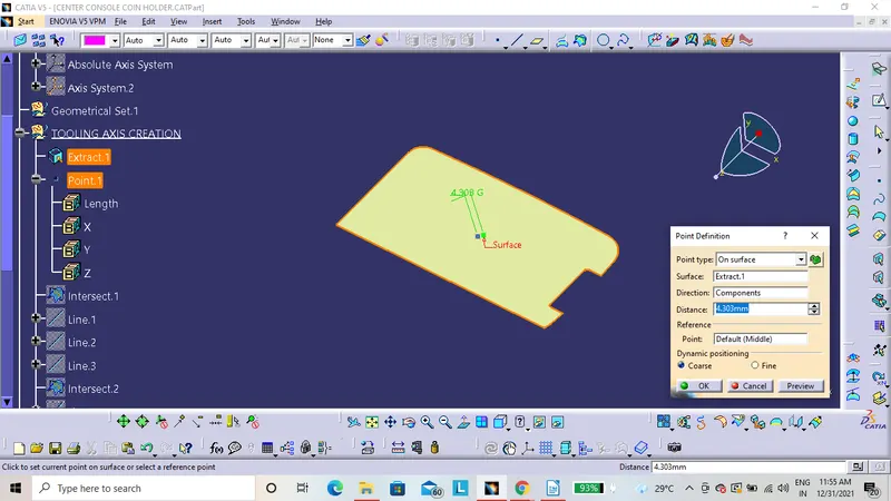
-
I will create an axis system, from that axis I will get two cross-sections by using that cross sections lines i will create the tooling axis for the surface.
-
Taken cross-section along ZY plane.
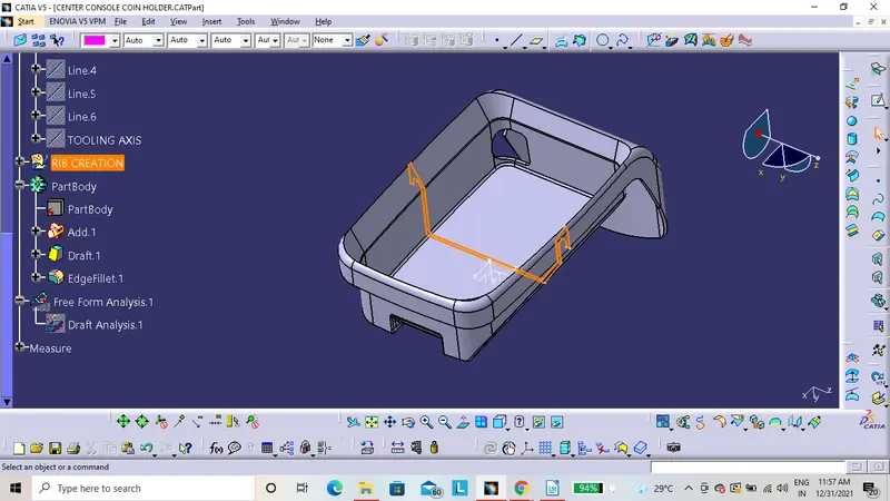
-
Clearing tooling axis along Y direction.
-
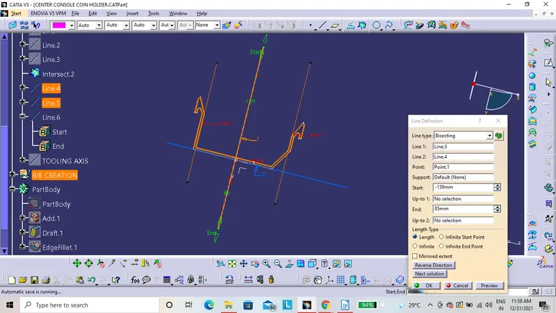
Now creating a cross-section along the ZX plane.
-
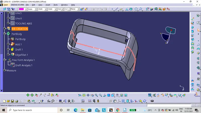
Clearing tooling axis along the X direction.
-
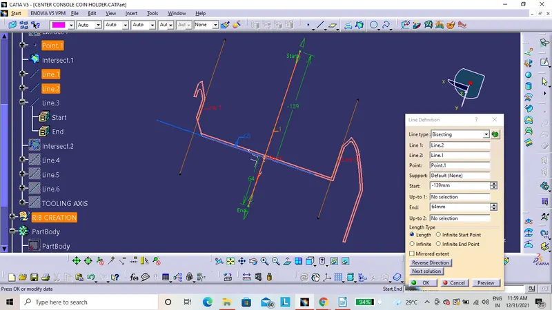
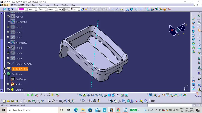
then using both tooling axis I can now create the main tooling axis for the given solid body by bisecting method.
Creating the rib on the coin holder:
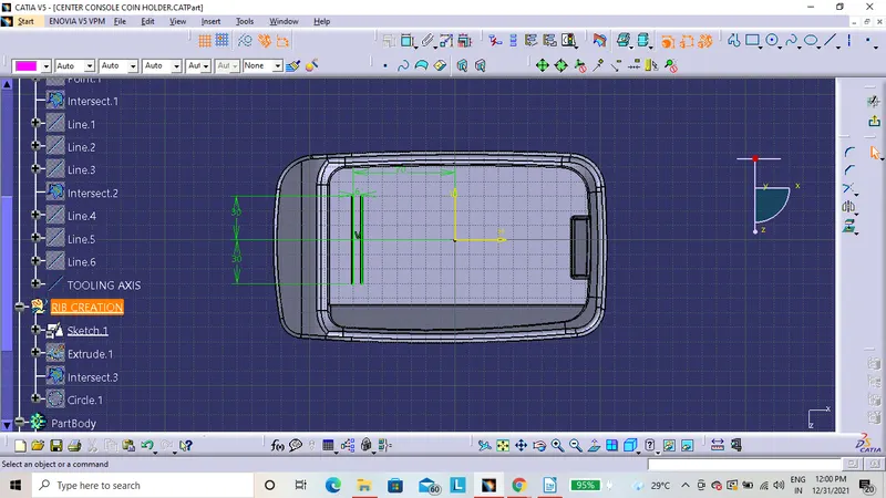
- Draw a line on the base surface of the coin holder with using portion sketch.
-
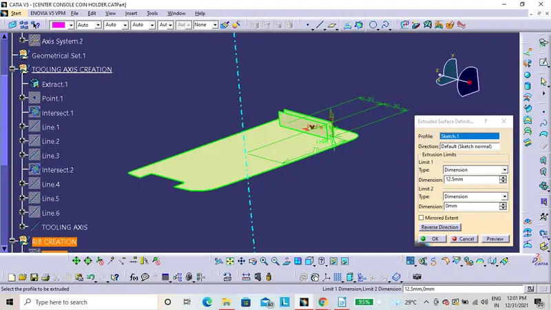
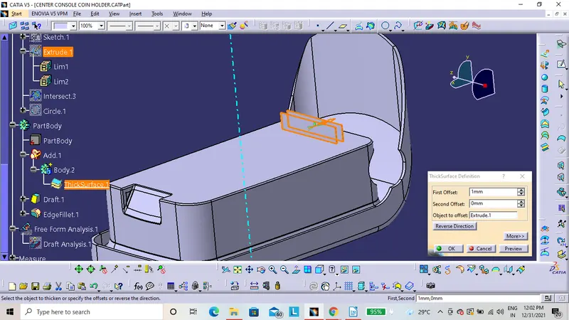
Construct the line with using axis. and extrude the this line and add thickening for this surface.
-
Add thickness of the rib 0.4*thickness of the component
-
Coin holder thickness is 2.5. so consider the rib thickness is 0.4x2.5 = 1mm
-
Give the draft angle is 0.5 for the rib.
-
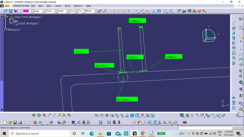
Height of the rib is 5*thickness.
-
Thickness is 2.5 so height of the rib is 5*2.5 = 12.5
-
Rib root thickness is D = 2.686
-
Space between the two ribs is 3:1 ratio
-
Height of the rib is = 12.5
-
Space between the ribs = x
-
Ratio = 3
-
X =12.5/3 = 4.1 mm is minimum.
Free form analysis:
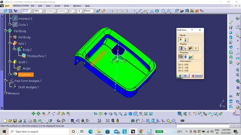
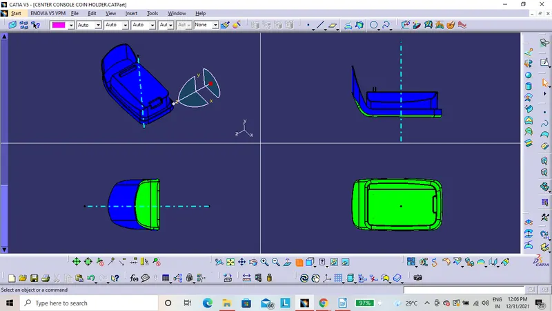
- Free form Analysis is done to ensure the part we drafted is easily removed from the Core and Cavity. In order to do that Go to Insert > Analysis > Feature Draft Analysis. Now Draft Analysis popup appears. There in direction section select the compass to define the draft direction. Drag the compass and place it on the Tooling Axis direction, then lock the draft direction. Now select on the Class A Surface which shows the positive and the negative angles in two different colors. Green is Positive angle and Blue represents the negative angle. With 3 degree set in positive angle and -0.1 in the negative angle we have the tooling axis direction clearing the draft analysis. So the Tooling axis is the proper direction.
RESULT:
- Created the rib for the Center console coin holder considering the design rules.