Week 8 - Simulating Cyclone separator with Discrete Phase Modelling
Empirical models for Cyclone Separator Efficiency:
Iozia and Leith Model:
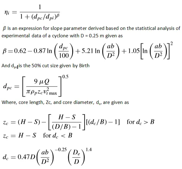
Iozia and Leith logistic Model is a modified version of Barth (1956) model which is developed based on force balance. The model assumes that a particle carried by the vortex endures the influence of two forces: a centrifugal force Z, and flow resistance, W.
The collection efficiency i of particle diameter dpi can be calculated by
Li and Wang Model:
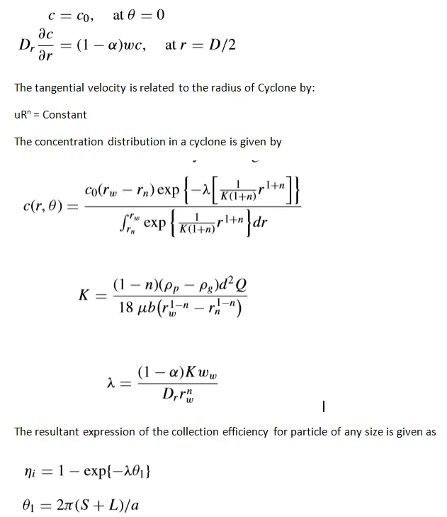
The Li and Wang model include particle bounce or re-entrainment and turbulent diffusion at the cyclone wall. A two-dimensional analytical expression of particle distribution in the cyclone is obtained. Li and Wang model was developed based on the following assumptions:
- The radial particle velocity and the radial concentration profile are not constant, for uncollected particles within the cyclones.
- Boundary conditions with the consideration of turbulent diffusion coefficient and particle bounce re-entrainment on the cyclone wall are:
Koch and Licht Model:
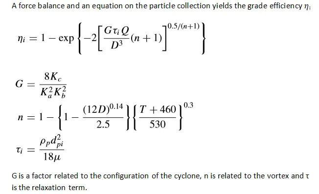
Koch and Licht collection theory recognized the inherently turbulent nature of cyclones and the distribution of gas residence times within the cyclone.
Koch and Licht describe particle motion in the entry and collection regions with the additional following assumptions:
- The tangential velocity of a particle is equal to the tangential velocity of the gas flow, i.e. there is no slip in the tangential direction between the particle and the gas.
- The tangential velocity is related to the radius of cyclone by uRn =constant.
Lapple Model:
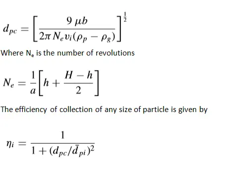
Lapple model was developed based on force balance without considering the flow resistance. Lapple assumed that a particle entering the cyclone is evenly distributed across the inlet opening. The particle that travels from inlet half-width to the wall in the cyclone is collected with 50% efficiency. The semi-empirical relationship developed by Lapple to calculate a 50% cut diameter, dpc , is
Geometry:
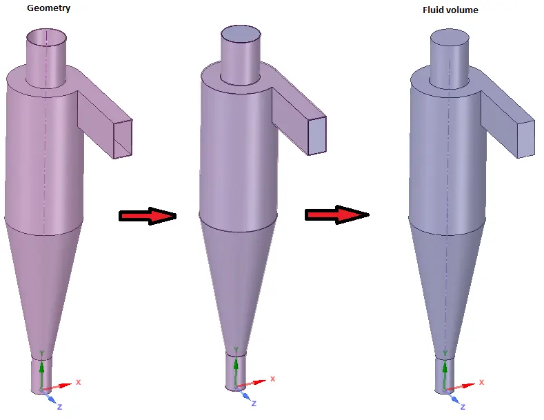
Meshing:
- we can create good mesh with help of “Cut cell” method available in assembly option in fluent, for generation of structural mesh.
- Because structural Mesh gives the best results.
- The element size considered to mesh the model is 1mm with cutcell mesh technique.
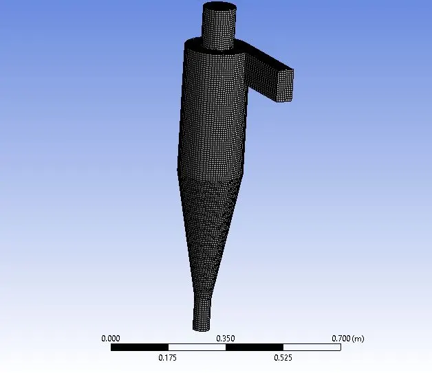
Number of nodes=75,733
Number of element=72,758
Solver Setting:
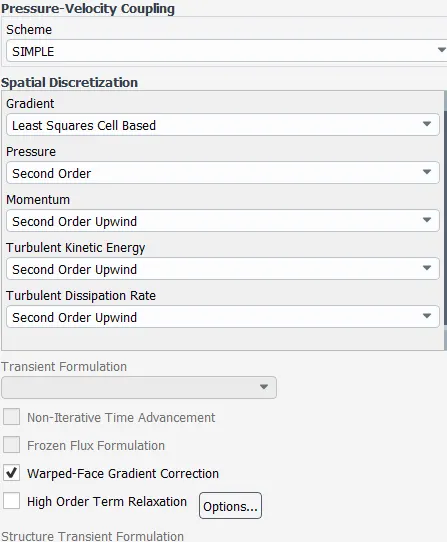
SImple scheme with Turbulent Kinetic Energy and Turbulent Dissipation rate to be second Order upwind.
Gravity is turned on
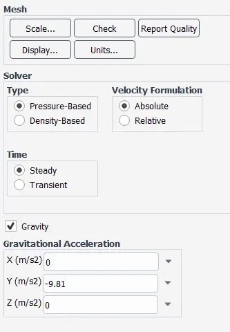
The turbulance model is K-epsilon RNG as it's good at capturing Swirl Flows.
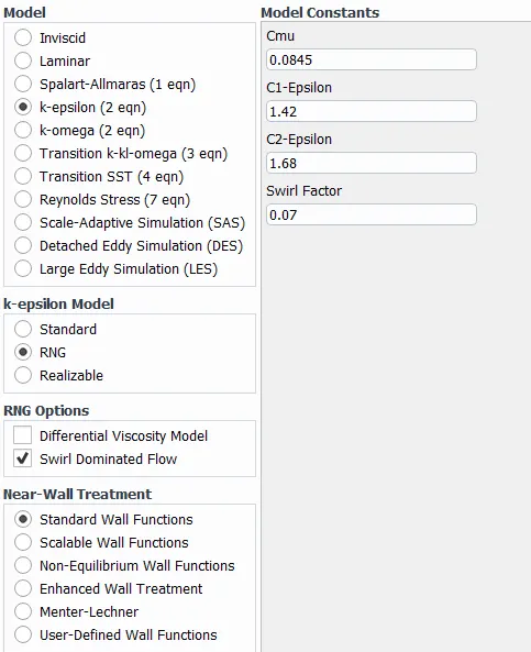
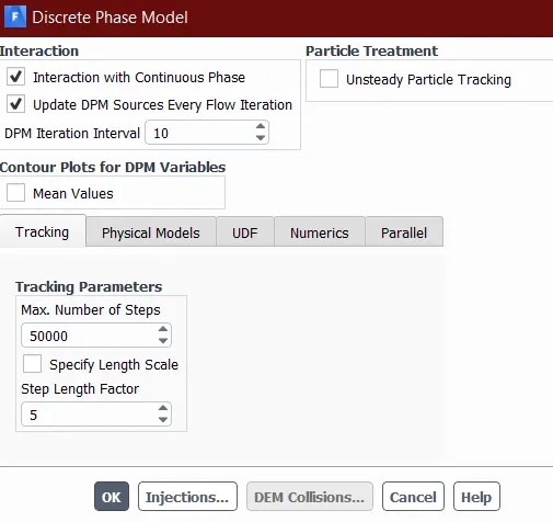
Discrete Model Phase:(Coupled Flow)
Solution Initialization:
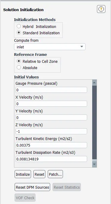
The simulation runs for 900 iteration considering it a steady state simulation.
Result:
For Inlet velocity =3 m/s , the model is simulated for different diameter of solid particle
1. Diameter=1 μm
Residual Plot
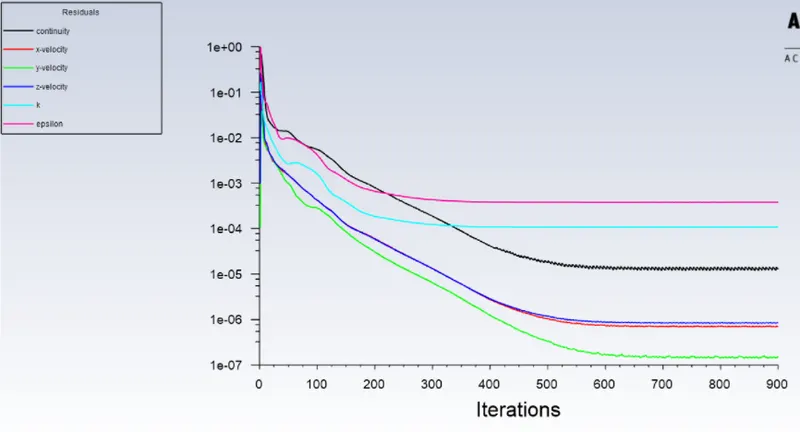
Cyclone Separator efficiency = Particle trapped/Particle traced = 37/120 = 0.3083
Cyclone Separator efficiency = 30.8%
Vortex Core:
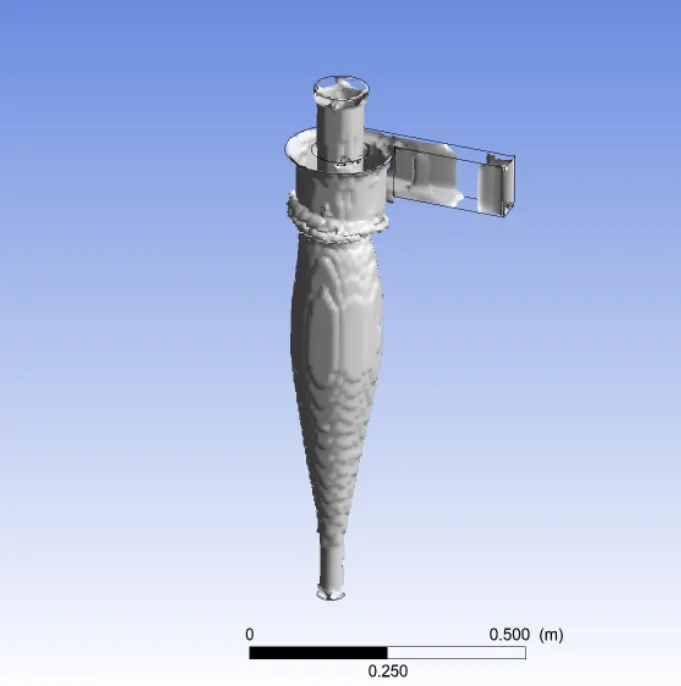
2. Diameter=3 μm
Residual Plot
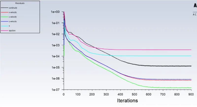
Cyclone Separator efficiency=Particle trapped/Particle traced=84/120=0.7 = 70%
Vortex Core:
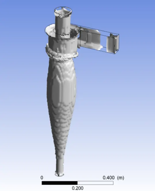
3. Diameter=5 μm
Residual Plot:
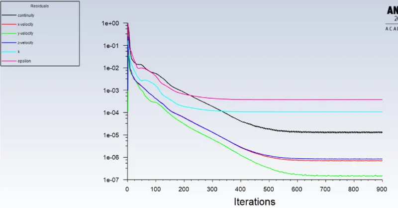
Cyclone Separator efficiency=Particle trapped/Particle traced = 119/120 = 0.9916 = 99.1%
Vortex Core:
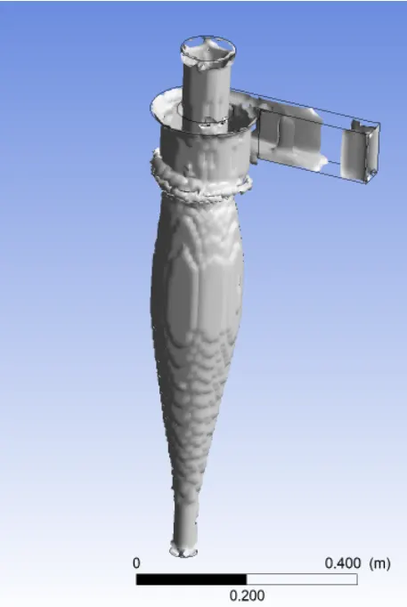
Data Table 1
| SN |
Diameter ( μm) |
Tracked | Traped | escaped | Incomplete |
Mass flow(inlet) Kg/s |
Mass flow(outlet_1) Kg/s |
Mass flow(outlet_2) Kg/s |
| 1 | 1 | 120 | 37 | 54 | 29 | 0.0197841 | -0.0163224 | -0.00346164 |
| 2 | 3 | 120 | 84 | 36 | 0 | 0.0197841 | -0.0163224 | -0.00346164 |
| 3 | 5 | 120 | 119 | 1 | 0 | 0.0197841 | -0.0163224 | -0.00346164 |
For diameter of solid particle= 5 μm, the model is simulated for different inlet velocity
1. Inlet Velocity=1 m/s
Residual Plot:
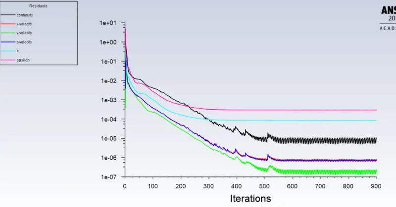
Cyclone Separator efficiency=Particle trapped/Particle traced=6/120 =0.05 = 50%
2. Inlet Velocity=2 m/s
Residual Plot:
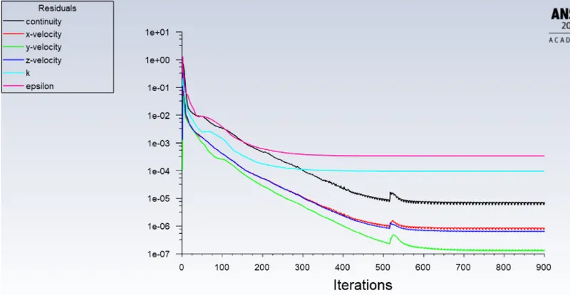
Cyclone Separator efficiency = Particle trapped/Particle traced = 86/120 = 0.7167 = 71.7%
3. Inlet Velocity=5 m/s
Residual Plot:
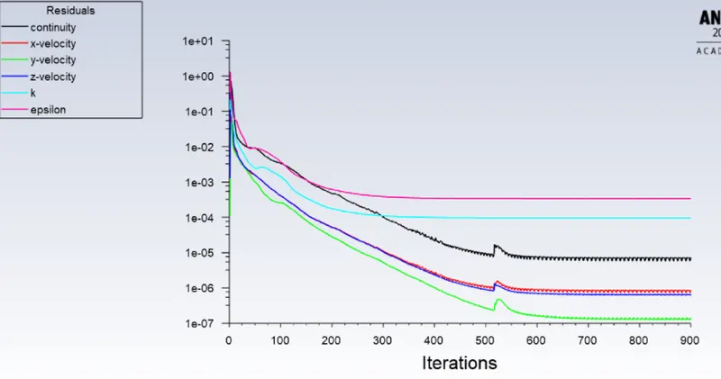
Cyclone Separator efficiency=Particle trapped/Particle traced = 115/120 = 0.9583 = 95.83%
Data table 2
| SN |
Diameter ( μm) |
Tracked | Traped | escaped | Incomplete |
Mass flow(inlet) Kg/s |
Mass flow(outlet_1) Kg/s |
Mass flow(outlet_2) Kg/s |
| 1 | 1 | 120 | 6 | 26 | 88 | 0.0197841 | -0.0163224 | -0.00346164 |
| 2 | 3 | 120 | 86 | 8 | 26 | 0.0197841 | -0.0163224 | -0.00346164 |
| 3 | 5 | 120 | 115 | 5 | 0 | 0.0197841 | -0.0163224 | -0.00346164 |
Conclusion
Cyclone separator works on the inertia. The lighter components of this gas have less inertia, so it is easier for them to be influenced by the vortex and travel up it. Contrarily, larger components of particulate matter have more inertia and are not as easily influenced by the vortex and collected at bottom. So, cyclone separator is more efficient at high inlet velocity. Simulation is too more stable at higher velocity.
Size of particulate matter have not significant effect on simulation but on efficiency. Efficiency of cyclone separator increses with increase in size of particulate matter.
From table 1 and table 2, we can observe that mass flow rate mainly depends on inlet velocity and size of particulate matter have negligible effect.